Hood design-Week 2
Hood design-Week 2
Aim:- Design Hood Outer Panel, Inner Panel and the necessary reinforcements by following the Master Section mentioned with the Design parameters explained in the videos.
Introduction:-
Hood is main component of a car at the front portion. It is used to decorate the car & add luxurious look. The shape of the bonnet is made aerodynamic in order to minimize the air effect.
Hood design consideration:-
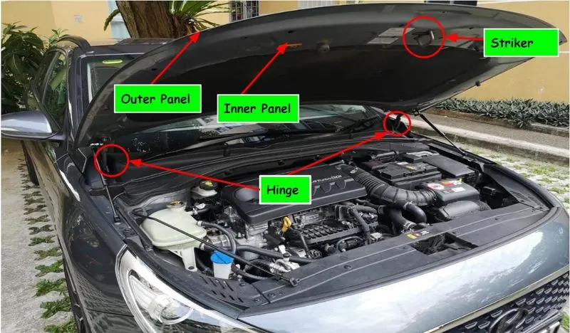
The hood of a car is considered as the frontal BIW enclosure component. Bonnets are designed to reduce air resistance as the air flows around the car. Apart from this, bonnets are also designed to meet several other requirements. They serve a great deal of purpose in protecting the passengers inside the car & the pedestrians in the event of an accident. It also acts as the cover for the engine.
- The European New Car Assessment Programme (Euro NCAP) is a European car safety performance assessment program which has developed test specifications & rating systems for assessing pedestrian injuries during impacts with the front of vehicles such test include a series of tests using impacts designed to bio-mimic a collision at speed of 40 km/h.
- They describe a situation in which a pedestrian is situated laterally & a car first hits one of his legs. Test are conducted on the leg, upper leg & most importantly the head, as head trauma is most commonly responsible for casualties.
- So to avoid severe injuries to the head, the high impact area for adults & children are subjected to less thickness. Also no reinforcement should be provided in that area as during head collision, the hood will absrob the head impact energy leading to collapse of the hood & thus protecting severe head injury.
- Another important criteria for the hood design is the protection of the occupants inside the car during front collision. The design of the hood should be in a such a way that the during the collision, the force should travel in the upward direction through the embosses & directed towards the body of car. Thus protecting the occupants inside.
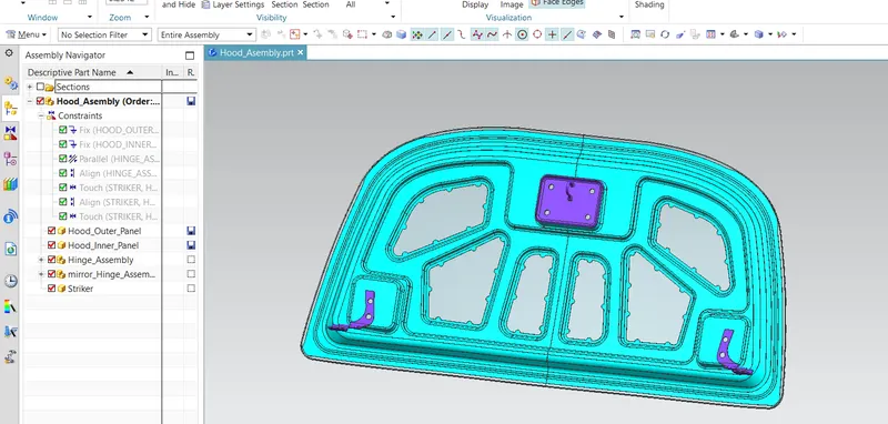
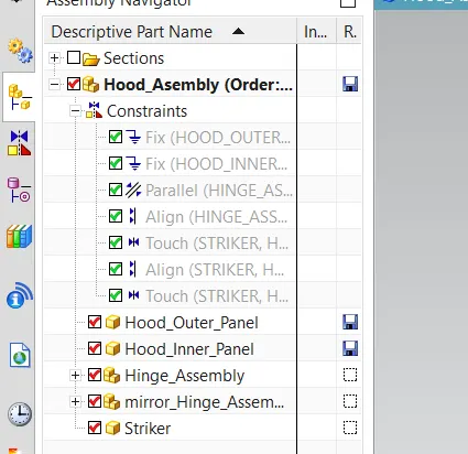
Following parts are using in hood assembly for this report,
- Hood outer panel
- Hood inner panel
- Hinge assembly
- Striker assembly
Hood thickness-
Outer panel thickness= 0.75 mm
Inner panel thickness= 0.75 mm
Reinforcement thickness= 1.5 mm
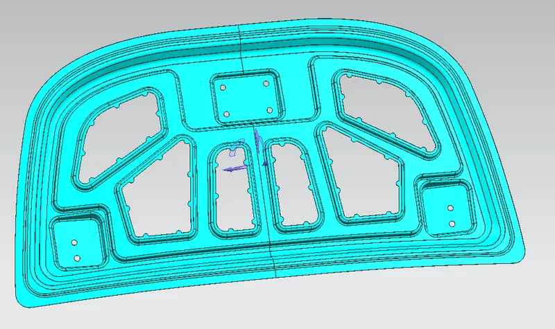
1.Hood Inner Panel:-
Inner panel for a vehicle is provided to improve rigidity, durability, and pedestrian protecting performance by comprising a composite structure in which a multi-cone structure and a frame structure are individually arranged on the front and the rear.
In general ,the hood panel is installed in the front of the vehicle so as to protect parts in the engine compartment and the engine compartment and at the same time open and close the hood panel for replacement and repair of components in the engine compartment.
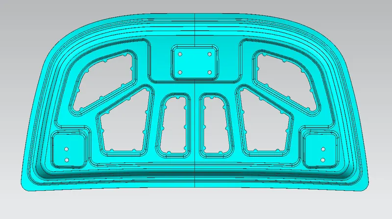
2.Hood Outer Panel:-
Hinge Assembly:-
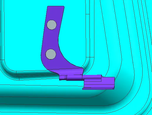
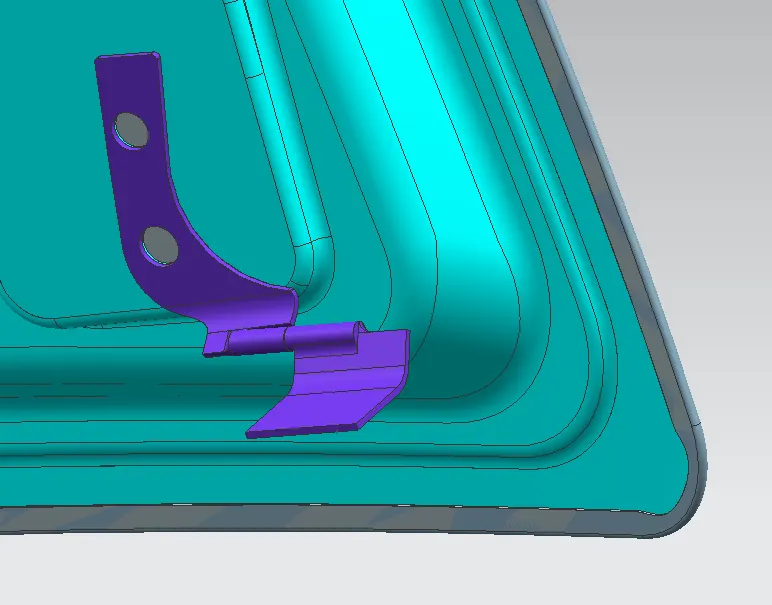
Hinge is a component that fixes the hood to the fenders of the car. The latch must be fixed perpendicular to the hinge axis so that the hood opens or closes properly.
Striker Assembly:-
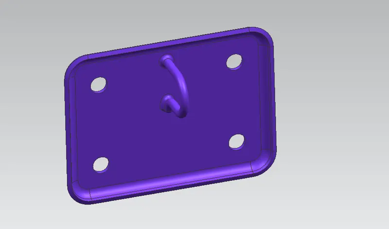
Latch & striker is used for locking the hood with the car. It is usually placed on the space provided on the inner panel
The process involved in designing hood as a sheet metal operations is
- Blanking
- Hemming
- Punch cutting or piercing
- Deep drawing
- Embossing
Hemming-
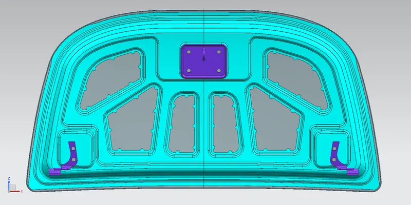
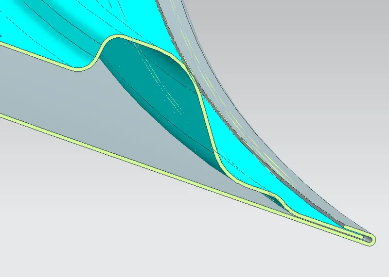
- Hemming is a sheet metal forming process in which sheets are joined by bending it usually to 180 degree. Automotive body panels & parts such as deck-lids, trunk-lids, doors, hoods & tailgates are formed by hemming processes.
- Roll hemming is carried out incrementally with a hemming roller. An industrial robot guides the hemming roller & forms the flange. Roll hemming operation can also be divided into several pre-hemming & final hemming process steps.
- Coventional die hemming is suitable for mass production. In die hemming, the flange is folded over the entire length with a hemming tool. Normally the actual hemming is a result of a forming operation in which the flange is formed with a hemming tool after the drawing & trimming operations have been completed.
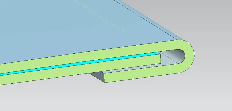
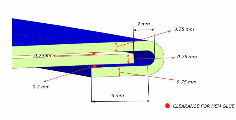
While doing the hemming process a relief angle is formed as a product of hemming when attaining at the corner of the sheet.
Deep Drawing-
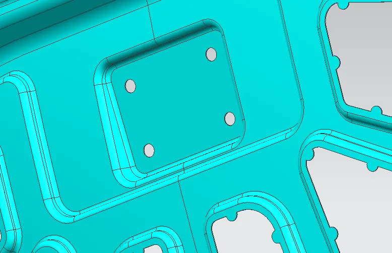
- Deep drawing is a manufacturing process that is used extensively in the forming of sheet metal into a cup or box-like structures. Pots & pans for cooking, containers, sinks, automobile parts, such as panel & gas tanks, are among a few of the items manufactured by sheet metal deep drawing.
- A deep drawing of sheet metal is performed with a punch and die. The punch is the desired shape of the base of the part, once drawn. The die cavity matches the punch and is a little wider to allow for its passage, as well as clearance. For many calculations, the sheet metal thickness is assumed to remain constant. There are changes in thickness in certain areas, due to force involved.
Embossing-
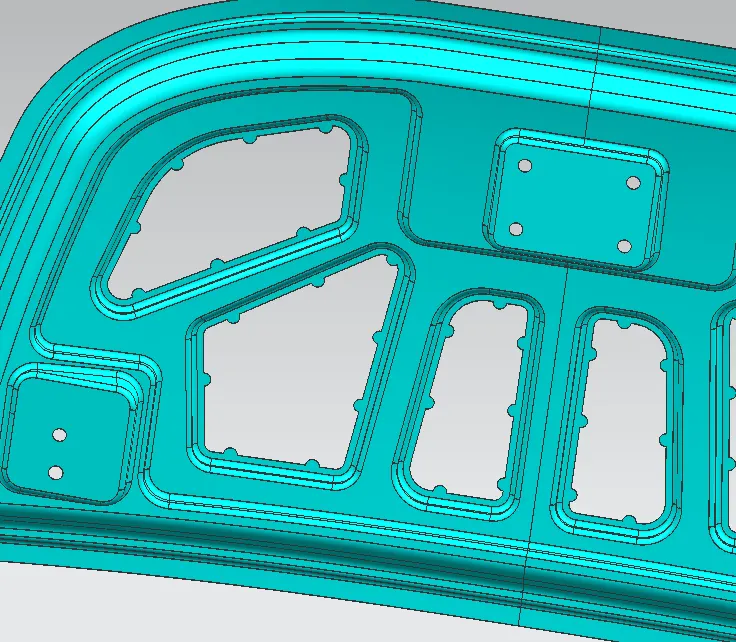
- The sheet metal embossing operation is commonly accomplished with a combination of heat & pressure on the sheet metal, depending on what type of embossing is required.
- A sheet metal is drawn through the male & female roller dies, producing a pattern or design on the sheet metal. Depending on the roller dies used, different patterns can be produced on the sheet metal.
Latch trajectory-
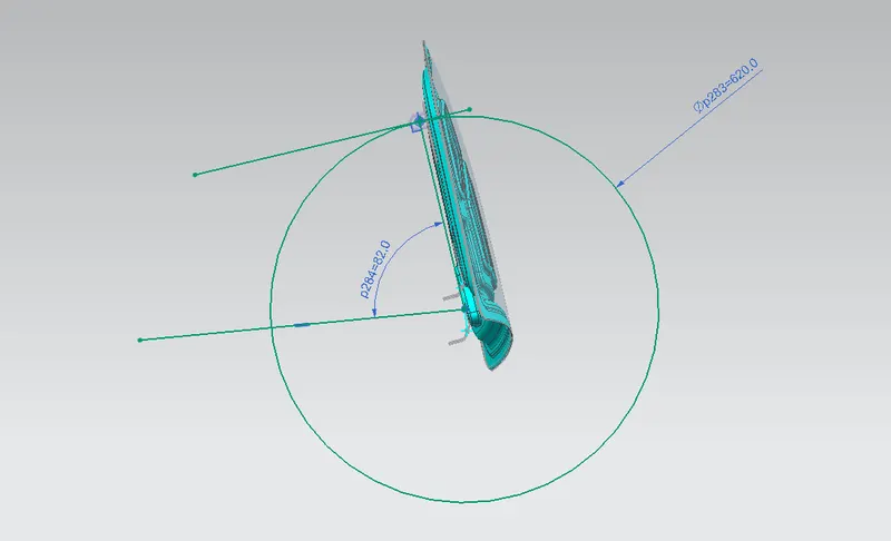
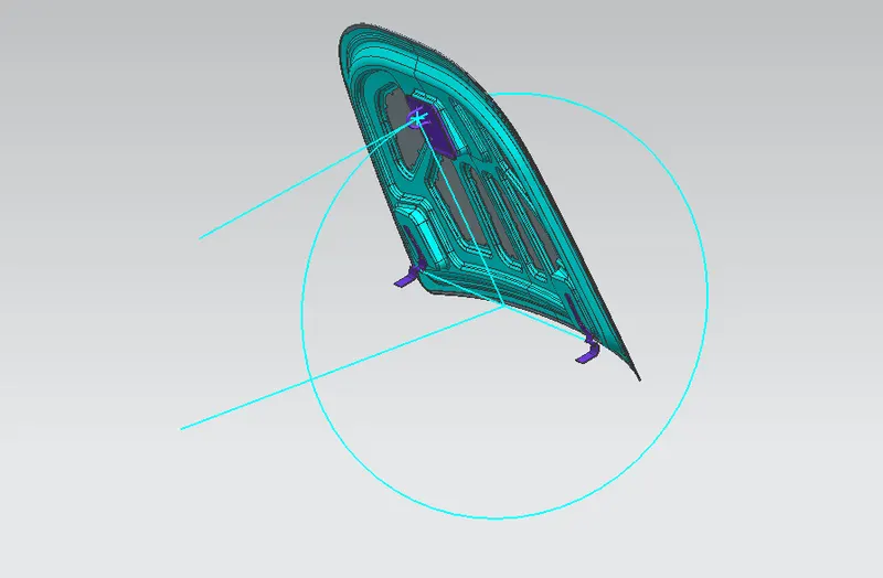
While opening or closing the hood, the latch must be perfectly aligned to the fixing or striker point. For that, the latches trajectory must be perpendicular to the hinge axis.
Mastic data:-
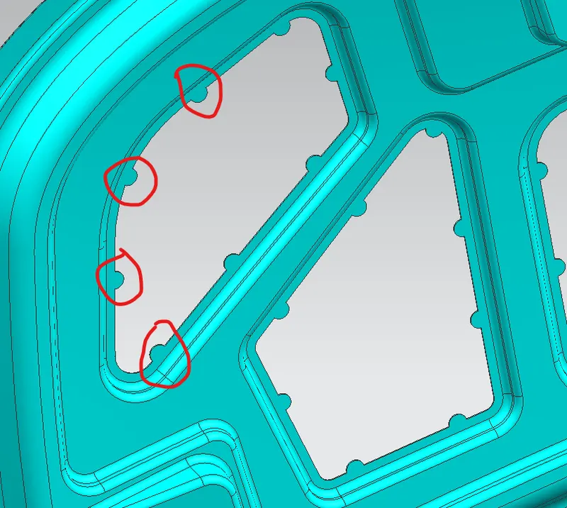
MAstic is the sealant applied between hood's outer panel (which is styling surface) and hood's inner panel cirlces in the figure above are the regions where mastic sealants are appiled Mastic Sealant have 80 mm diameter range of effect which holds and joins the outer panel and inner panel having 5mm thickness
HOOD DESIGN steps:
There lot more things before the hood gets in to designing hands that to be considered.
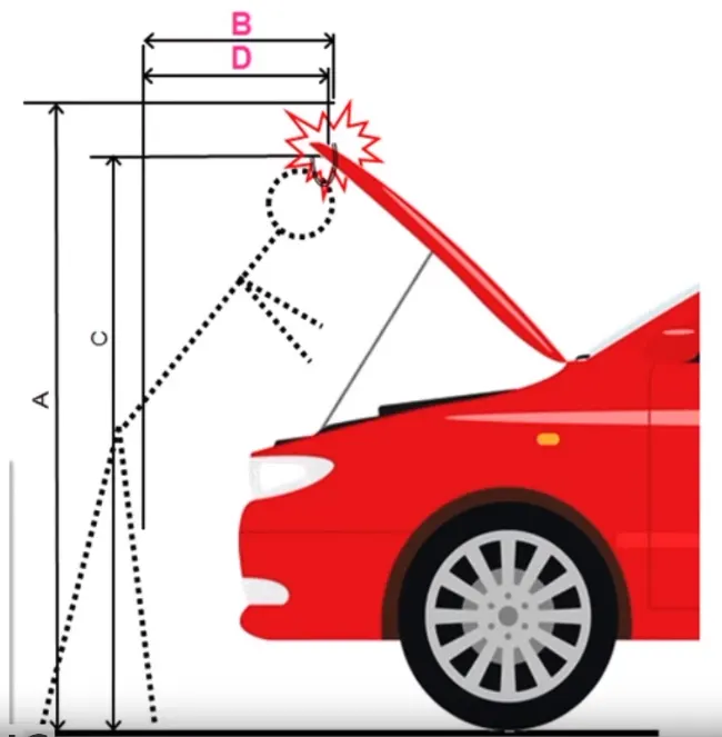
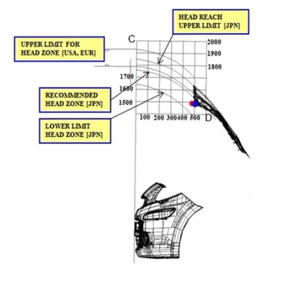
The height of the hood is designed based on the country standards as the height of a average person changes from place to place.
The material consideration is also required that should be cost effective to manufacture.
The Hood should be designed with a light weight for the pedestrain saftey as the person hit to hood there should be minimal harm to the person.
The input design for the input panel is given below :
Inner panel design steps:-
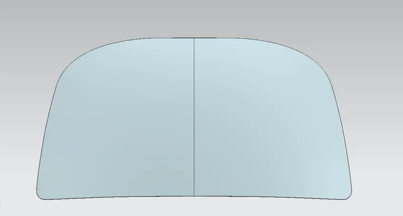
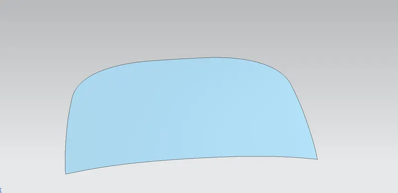
Class A surface is given of hood outer panel
So now along with the part the master section is also provided
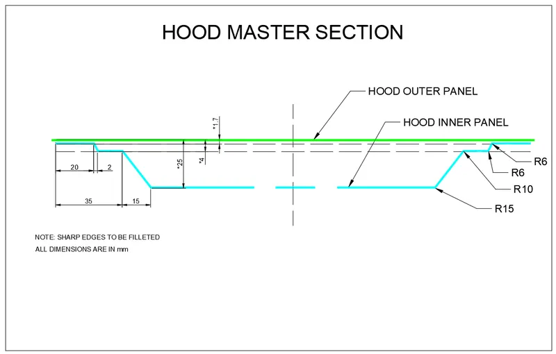
So initially according to the masters section, here the inner panel is designed. The surface is offset to 1.7mm, 4mm and then to 25mm. And then the trim surface option is used to give the required shape as shown in the figure below.
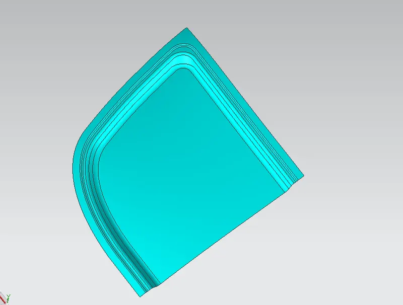
Then the emboss command is used to create the surface for the inner panel design as shown in the figure below.
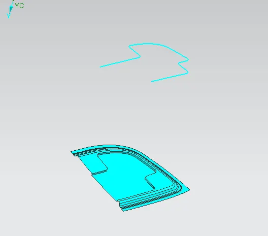
Now here comes the task for us, as a design engineer we need to create the inner emboss design in such a way that all the frontal impact forces applied on to the hood should get dissipated on to the direction of the hinge assembly i.e in the Y direction without getting direct impact on the driver’s side.
So the hood inner design is done as shown in the figure below, but here instead of emboss the law extension command is used.
Now this entire geometry is mirrored on to the other side
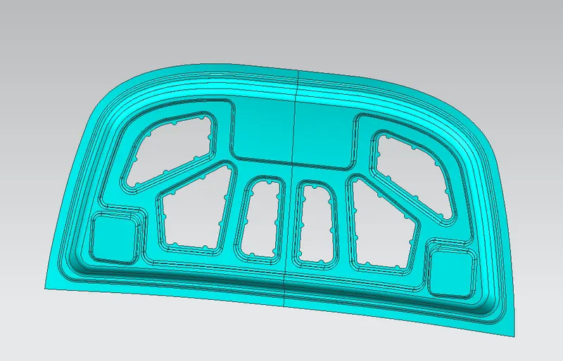
Now thicken the surface to 0.75mm
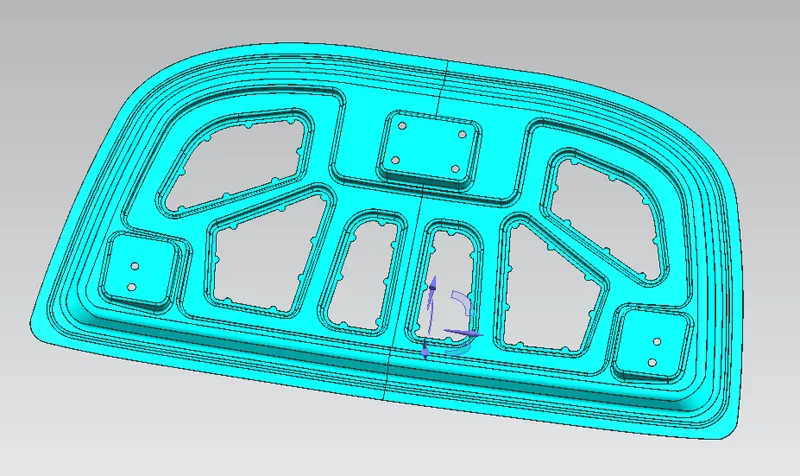
Outer panel design steps:-
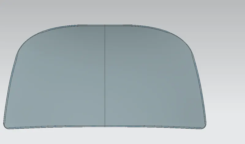
Now to the given outer hood surface create hemming
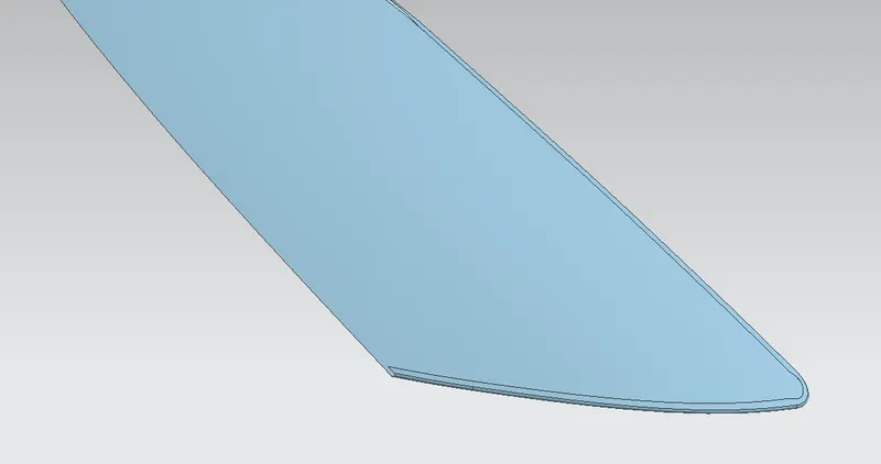
Then give the So the relief is provided
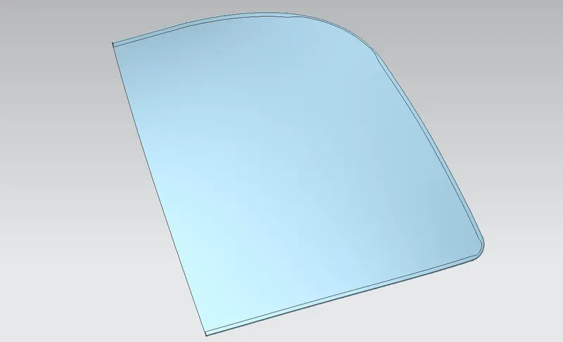
Then mirror and thicken it to 0.75mm
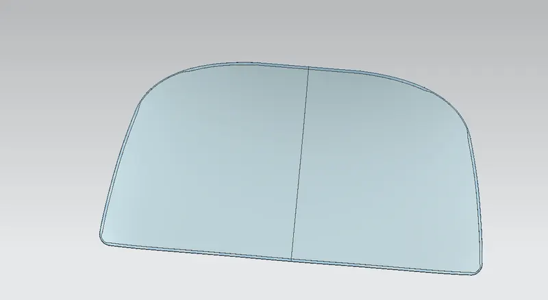
Assembly:-
Now we need to mount the hinges on to the hood inner panel in such a way that we can be able to find the striker trajectory also.
So here initially the hinges are placed roughly as shown in the figure below.
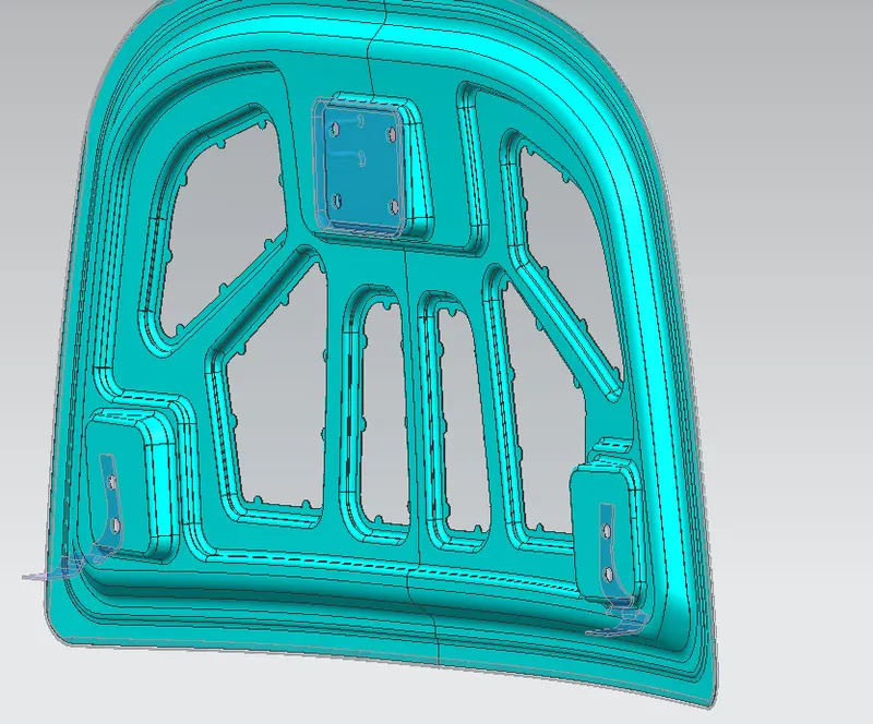
Then as we are going to place the hinge on to the inner panel, the place where the hinge is placed loose the strength and then to add the strength we need to give the reinforcement as shown in the figure below.
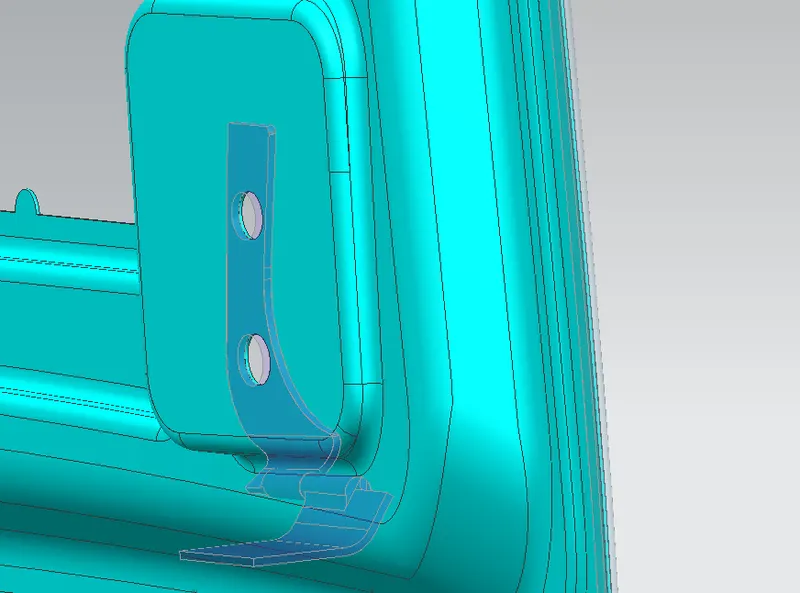
Reinforcement is nothing but the addition of the material base to provide strength to the component.
Now mirror the hinge
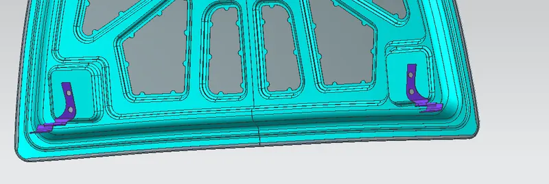
Now as the hinge is placed and the constraints are given to the hinge assembly we need to draw the trajectory of the striker following the path.
For this the center points on to the hinge axis are created and then the line is drawn parallel to the hinge axis and then from this center the circle is drawn to locate the position of the striker, latch is extracted and then the law extension command is used to create the emboss. Finally it is trim and extend and we get the striker emboss ready.
The striker emboss.
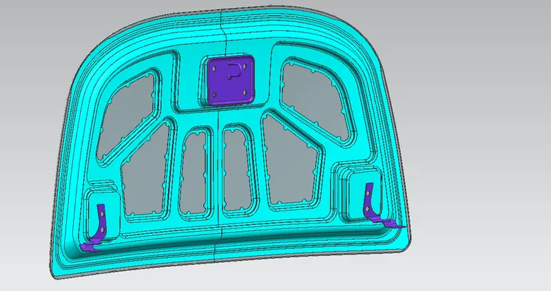
Finally the all the constraints are provided to the components and the whole design of the hood is ready.
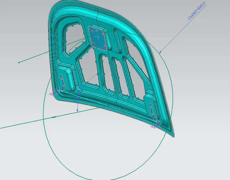
Final assembly ready
clip section
Tree structure