Hood design-Week 2
Design of a Car Hood
Objective:
To Design the Inner Panel and create an ASSEMBLY of hood by using Hood Inner Panel, Outer Panel, Latch, Hinge and Striker with the Reinforcement by given the Master Section and Design parameters.
List Of Contents:
- Introduction
- Parts of Hood
- Design Parameters of Hood
- Manufacturing Techniques
- CAD Modeling
- Assembly & Constraints
- Conclusion
1. Introduction:
What is hood?
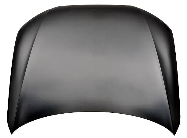
A car hood, also referred to as a “bonnet” in some countries, is the hinged cover that rests over the engine bay of a front-engine vehicle. The car hood protects the engine and connected parts from the elements while providing easy access for repairs and maintenance.
2. Parts of hood:
- Hood outer panel
- Hood inner panel
- Hood Hinge
- Latch and stricker
are the major parts of the hood aseembly. We are discussing about those parts of the hood in detailed manner below.
Hood outer panel:
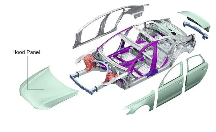
A car hood panel is one of the most important components of the BIW (body in white), it is considered as the closure sheet-metal component. A hood panel consists of two panels that are hemmed together to form the automotive hood assembly.
The inner panel of the hood is not visible to the customer but this is the engineering feature of the outer panel. The outer panel has the aesthetic look to it but on its own is very weak and not capable of handling force during impact.
Purpose of hood outer panel:
Traffic accidents are terrible scourge that occur in many countries, specially for developing countries where transportation affairs like tangled yarn.
- Besides functioning as an engine compartment cover, the hood of modern compact SUV can also help to manage the impact energy of a pedestrian's head in a vehicle-pedestrian impact.
- to absorb the impact energy of a pedestrian's head.
- to provide a robust design and homogeneous of Head Injury Criterion (HIC) for impact position
Hood inner panel:
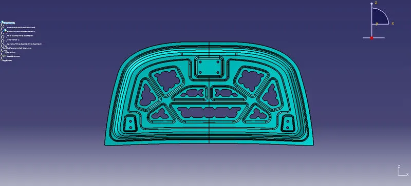
In general, the hood panel is installed in the front of the vehicle so as to protect parts in the engine compartment and the engine compartment and at the same time open and close the hood panel for replacement and repair of components in the engine compartment.The hood panel of the vehicle has a form in which an outer panel and an inner panel are combined, and has a frame structure for rigidity reinforcement in order to ensure hood rigidity and durability.
Hood Hinge:
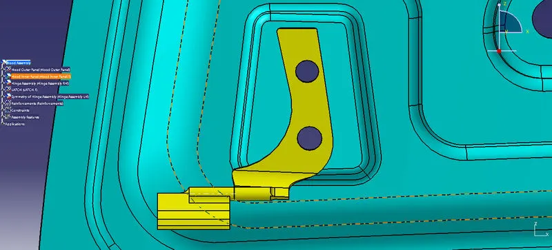
A hood hinge mechanism having a pivot pin having a D-shaped cross sectional shape positioned within a recess. The hood and pin are pivotal to a position whereat the D-shaped cross section is oriented to pass through a slotted opening to the recess to thereby allow the hood to be removed or installed on the vehicle.
Latch and stricker:
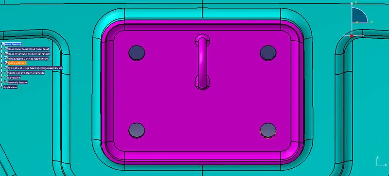
Latches are mechanical components that allow the temporary joining of moving parts relative to each other. They are actuated to release the coupling and allow the two parts to separate. They are mostly seen on doors and enclosures. They are used in devices such as seat belts, clamps, straps, and objects with retractable parts. Different designs feature different methods of actuation, holding style, and mounting.
In other words Hood latches are mechanical latching systems for hoods. Most vehicles, of course, have a hood. Hoods are square- or rectangular-shaped panels that lie flat across the front-end of a vehicle. They are designed to cover equipment like the vehicle’s motor, transmission, radiator, alternator, battery and other components. If you need to access any of these components, though, you’ll have to open the hood. You can open the hood on a vehicle by engaging the hood latch. Hood latches typically connect to a cable. Engaging the hood latch will release this cable, after which you can lift the hood.
Design Parameters of hood:
- Hood head zone
- Hood opening angle
- Pedestrian safety
- Embosses
- Cutouts
- Mastic points
- Reinforcements
- Latch Trajectory
Hood head zone:
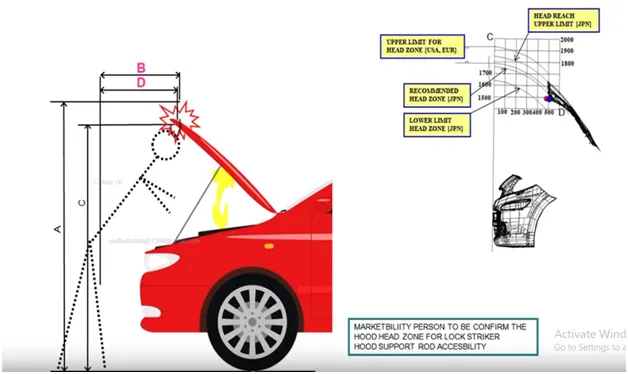
In-vehicle to pedestrian collisions, the main reason for fatal injuries is the pedestrian to vehicle impacts, which are caused by the direct impact of the pedestrian head to the front part of the automotive hood during a collision. This paper deals with the development of a new finite element model to simulate the car-to-pedestrian front impacts between the adult headform and vehicle hood composite structures according to the EURO-NCAP requirements.
Hood opening angle:
A gas strut (also referred to as a gas spring) is a spring that operates due to the force exerted by the compressed gas (usually Nitrogen) stored inside the cylinder. Luxury carmakers provide a gas strut to lift the hood and hold it in place. It takes minimal efforts to lift an otherwise heavy hood and lends that upmarket feel to the car
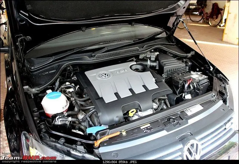
There are two types of supporting element commonly used for hood lifting.
- Supporting rod
- Gas stay
Supporting rod:
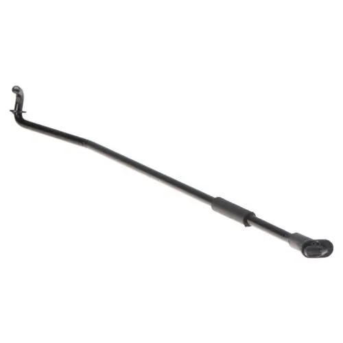
Support rod is basically long cylindrical rod. It safely keep an engine hood in an open state even if external forces are abruptly generated due to vibration & wind.
Gas stay:
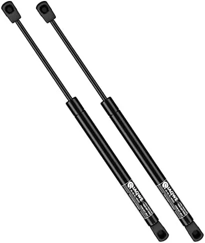
Gas springs are largely used in automobiles to lift the boot door in hatchbacks. They also find applications in furniture (beds, rack doors etc.), marine (hatches, doors etc.) and industries. Gas springs come in various sizes, lengths, force ratings and different end fixings depending on the application. A kitchen shelf door may not require a gas strut with a force rating or stroke length as that required by a car's hood.
Pedestrian Safety:
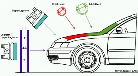
The Pedestrian Protection System (PPS) is a system which, in certain frontal collisions, contributes to mitigating a pedestrian's impact with the car. In certain frontal collisions with a pedestrian, the sensors in the front of the car react and the system is activated.
In other words A pedestrian can be defined as a vulnerable road user that is at risk when it comes to roads. Thus the safety of such being is essential. The pedestrian safety and protection norms are aimed to do so. It will ensure that the new cars meet a minimum requirement of safety for the pedestrians
Emboss:
Emboss is given so that during the crash the energy is dissipated outside or away from the vehicle occupants and along with the other cut outs to reduce the weight. Also its help to improve the strength of thr hood inner panel.
There are three kinds of embosses given in the hood design.
- Master section emboss
- Hinge emboss
- Latch emboss
Cutouts:
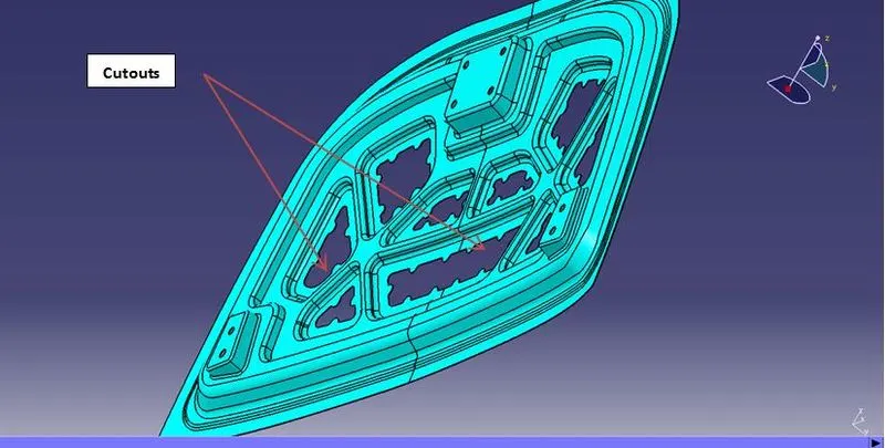
Generally cutouts are made for reduce the impact of the passanger and dissipate the force occur during the accidental force comes inside the car. As well its reduce the weight of the car in order improve the performance of the car
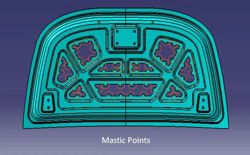
Mastic Points:
The main function of mastic point is to reduce NVH(Noise ,Vibration and Harshness) that created on hood. So, by providing more in number of mastic points at center area of hood will increase the performance of car. The hood inner panel and outer panel are joined using the mastic sealant instead of welding or other joining methods because the outer panel is a cosmetic part and it needs to have a smooth and attractive surface finish. The mastic sealant also further improves the flexural rigidity of the entire assembly.
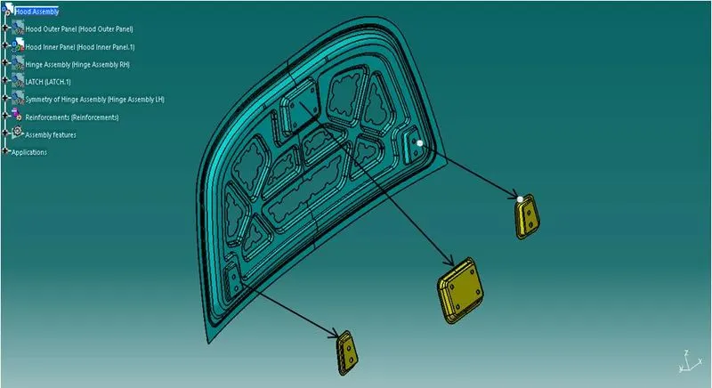
Reinforcement:
Car manufacturers use sound absorption elements for the noise reduction of their vehicles. These elements are mostly made of heavy foamed plastics / polyurethane (PUR) hard foam, bitumen or composite materials. They are typically assembled or applied in spaces which allow merely an extremely flat construction, such as underneath the hood / bonnet or under the headliner
- Deformation
- Shear forces
- Slipping / shifting out of position
- Traction
- Friction / abrasion
- Impacts
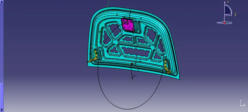
Latch Trajectory:
Latch Trajectory is the angular path in which the latch should be positioned to lock the hood. The trajectory is drawn based on the reference of the Hinge joint central axis like given below.
Manufactring techniques:
Stamping Process:
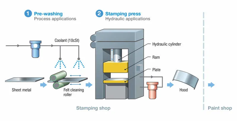
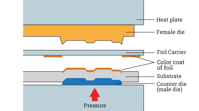
Sheet metal embossing is a stamping process for producing raised or sunken designs or relief in sheet metal. This process can be made by means of matched male and female roller dies, or by passing sheet or a strip of metal between rolls of the desired pattern. It is often combined with foil stamping to create a shiny, 3D effect. The metal sheet embossing operation is commonly accomplished with a combination of heat and pressure on the sheet metal, depending on what type of embossing is required. Theoretically, with any of these procedures, the metal thickness is changed in its composition.
Metal sheet is drawn through the male and female roller dies, producing a pattern or design on the metal sheet. Depending on the roller dies used, different patterns can be produced on the metal sheet. The pressure and a combination of heat actually "irons" while raising the level of the image higher than the substrate to make it smooth. The term "impressing" refers to an image lowered into the surface of a material, in distinction to an image raised out of the surface of a material.In most of the pressure embossing operation machines, the upper roll blocks are stationary, while the bottom roll blocks are movable. The pressure with which the bottom roll is raised is referred to as the tonnage capacity.
Deep drawing is a sheet metal forming process in which a sheet metal blank is radially drawn into a forming die by the mechanical action of a punch.It is thus a shape transformation process with material retention. The process is considered "deep" drawing when the depth of the drawn part exceeds its diameter. This is achieved by redrawing the part through a series of dies.
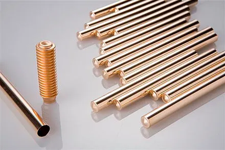
Example for Deep Drawing parts
Hemming:
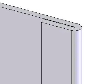
Hemming and seaming are two similar metalworking processes in which a sheet metal edge is rolled over onto itself. Hemming is the process in which the edge is rolled flush to itself, while a seam joins the edges of two materials. Hems are commonly used to reinforce an edge, hide burrs and rough edges, and improve appearance.
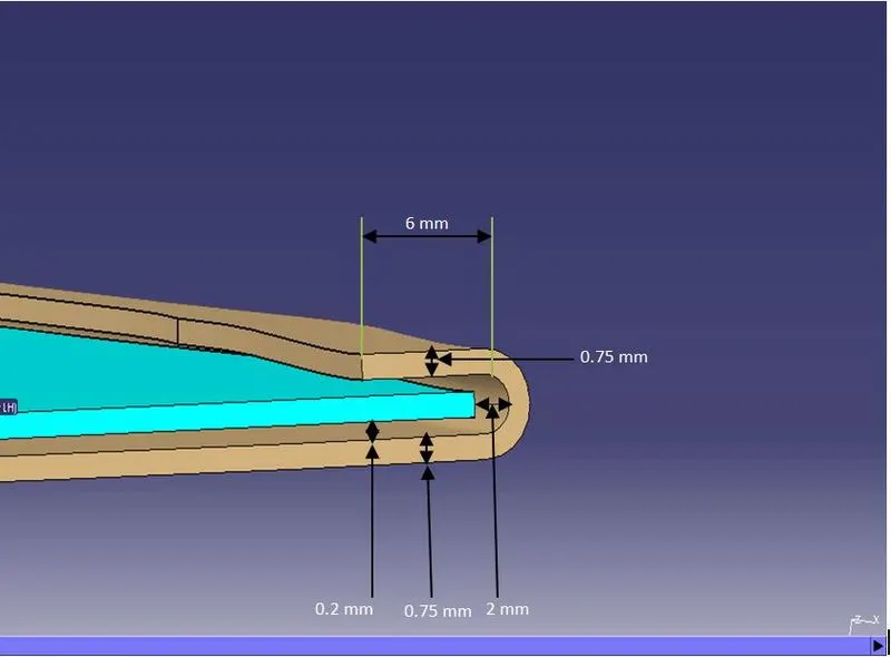
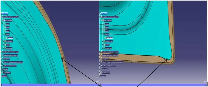
Hemming relief:
- During the hemming operation rollers rolls over the outer panel surface to join to panels together with hemming glue.
- but at the corner, the roller could not produce perfect hemming due to the presence of curvature. To avoid overlapping some of the material removed .
- Hence it is necessary to provide some relief at corners.
Process:
The process for both hemming and seaming are the same, except that the tonnage (amount of force exerted) requirement is greater for seaming. The process starts by bending the edge to an acute angle. A flattening die is then used to flatten the hem
There are two types of hemmed edges: closed hems and open hems. Closed hems are completely flush while open hems have an air pocket in the bend. The major difference is that the tonnage required for a closed hem is much greater than that for an open hem
Hemming is a forming operation in which the edges of the sheet are folded or folded over another part in order to achieve a tight fit. Normally hemming operations are used to connect parts together, to improve the appearance of a part and to reinforce part edges.
In car part production, hemming is used in assembly as a secondary operation after deep drawing, trimming and flanging operations to join two sheet metal parts (outer and inner) together. Typical parts for this type of assembly are hoods, doors, trunk lids and fenders.
The accuracy of the hemming operation is very important since it affects the appearance of the surface and surface quality. Material deformations, which occur during the hemming process, can lead to dimensional variations and other defects in parts. Typical hemming defects are splits or wrinkles in the flange, material overlaps in the corner areas or material roll-in. This is why it is important to use simulation tools in order to, on the one hand, better understand the hemming process and, on the other hand, significantly reduce the number of “trial and error” loops during tryout und production.
There are various types of hemming operations:
- Conventional die hemming
- Roll hemming
- Flat or closed hem
- Open hem
- Teardrop hem
- Rope hem
- Rolled hem
here we use
Roll hemming
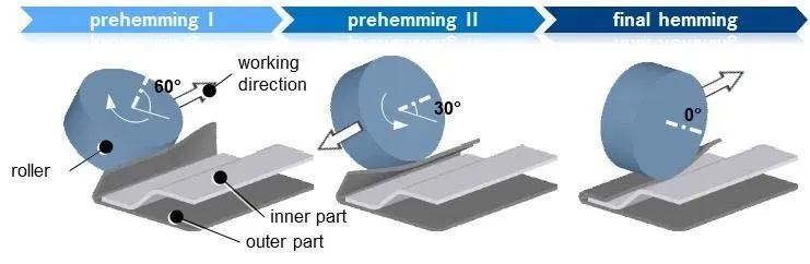
Roll hemming is carried out incrementally with a hemming roller. An industrial robot guides the hemming roller and forms the flange. Roll hemming operation can also be divided into several pre-hemming and final hemming process steps. Roll hemming is very flexible to use and tool costs are significantly lower as compared to those of conventional die hemming. However, the cycle times are much higher since the hemming is realized using a hemming roller which follows a defined path.
A complete list of hemming benefits on a sheet metal product is as follows:
- Hems strengthen the sheet metal edge
- They improve the surface appearance and surface quality
- They hide defects such as rough edges and burrs
- They can connect parts
- They make the edges safer to handle
Spot Welding:
The welding process which is used for welding two or more metal sheets together by applying pressure and heat from an electric current to the weld area is known as spot welding.
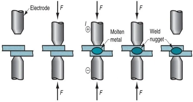
Spot welding is a type of resistance welding process, which is why it is also known as the resistance spot welding.The process uses two shaped copper alloy electrodes to concentrate welding current into a small "spot" and to simultaneously clamp the sheets together. Work-pieces are held together under pressure exerted by electrodes. Typically the sheets are in the 0.5 to 3 mm (0.020 to 0.118 in) thickness range. Forcing a large current through the spot will melt the metal and form the weld. The attractive feature of spot welding is that a large amount of energy can be delivered to the spot in a very short time (approximately 10–100 milliseconds).This permits the welding to occur without excessive heating of the remainder of the sheet.
CAD Modeling of Hood:
- From the given data for hood design the Master section is drawn
- 1st emboss drawn for strength
- 2nd emboss drawn for strength
- Cutouts drawn by giving correct positioning of mastic points
- Hinge Emboss drawn for positioning of hinges
- Striker emboss drawn for positioning of stricker
- Reinforcement done for both hinge and striker placement with the thickess of 1.5mm
- Inner panel thicknen by 0.75 mm
Assembly and Contraints of hood:
Hood Assembly consists of Hood inner Panel, Hood Outer panel, Reinforcement panels, Striker, Hinge,Mastics.
Steps invloved:
- Hood Assembly file created
- After create the inner panel hinges positioned at hinge emboss by giving Parallel and coincidence Contraints used.
- Trajectory drawn from the hinge axis for striker positioning and Parallel and Coincidence contraints used
- After all the surfaces extracted for reinforcement of hinge and striker
Draft Analysis of Hood:
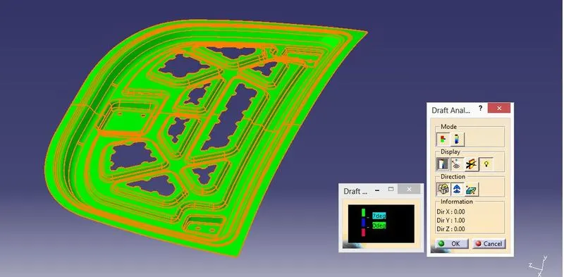
- The draft analysis is the technique used for analyse whether our part model created in CATIA is manufacturable based on the draft condition applied. So thatt he part should get easily removed from the panel dies or Mold.
- It's Impossible to withdraw the tool after part is making if it is having a straight 90-degree profile from its base surface. So a draft angle is provided to each and every area of the component in order to get easy removal of the component from the tool.
- Here we are providing a direction in which components should eject in order to get easy removal of components from the tool. In other words, it also lets us know whether the model is having a draft angle and how much is the draft angle from the tool direction.
Conclusion:
A detailed report about the Hood Design which includes a detailed explanation about hood and its components, Latch Trajectory, Mastic Data, Emboss Definitions, Manufacturing process like Deep-Drawing and Hemming, and all the parameters followed in the design are to be done.