Hood design-Week 2
HOOD DESIGN
HOOD
Hood is also called as Bonnet. It is hinged thin sheet which covers and protects the main parts of car like engine. Its main function is to direct access to the engine, battery and other crucial parts of the cars for repair and maintenance and to protect these parts from direct sunlight and dust.
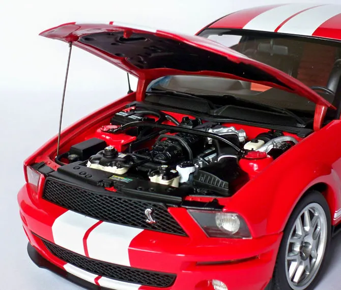
It also gives good looks and, help to design car aerodynamically stable.
Sometimes it is required to supply pure air so filter is provide on the bonnet to supply filtered inlet air. Hoods are provided with different vent designs for cooling purpose of an engine and carburator at high speed. Scoops on hood having another function of supply of air for supercharger in case of supercharged engines.
And last function of hood to handle this type of heavy engines with supercharger outside.
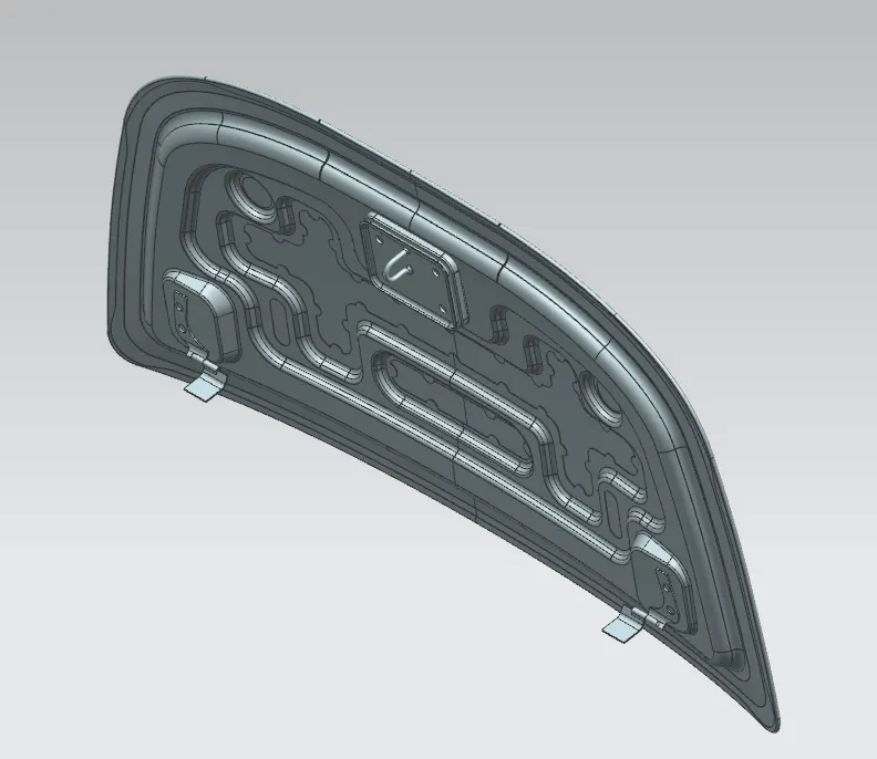
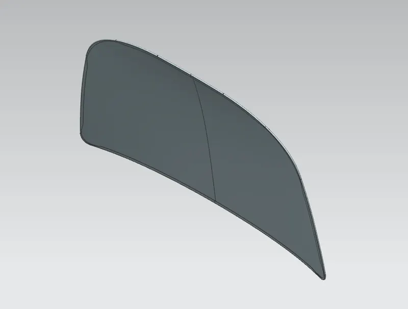
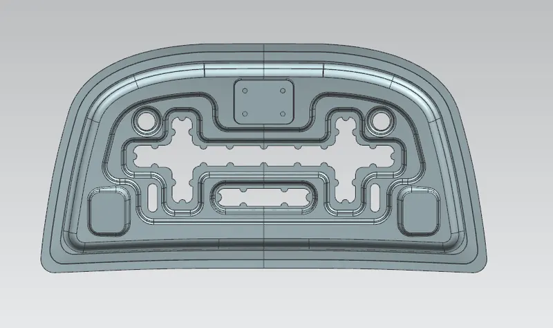
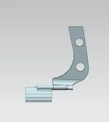
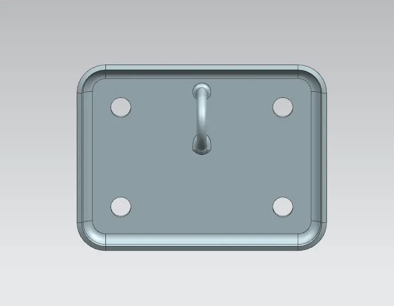
- Deep Drawing is one of the most popular metal forming methods available to manufacturers–it involves the use of metal dies to form blank sheets of metal into a desired shape. Specifically, if the depth of the item created is equal to or greater than its radius, then the metal forming process can be called deep drawing.
- The deep draw forming process begins with metal blanks. Typically, single blanks are used in order to facilitate the creation of parts or products with deeper shapes. Sometimes, these metal blanks will be placed on a reel to enable the metal to form efficiently. At each step in the deep drawing process, the metal blank is shaped through pressure applied by a metal die.
- Though deep drawing is similar to metal stamping, the terms are not interchangeable. Stamping does not leave a single machine until the metal has completely formed. In general, deep drawing is used to fabricate parts and products that are deeper than metal stamping can accommodate.
- The formability limitations of conventional deep drawing are a barrier for some industrial uses. Radial drawing stress and tangential compressive stress are a common concern that can result in wrinkling, fracturing or cracking in some applications.
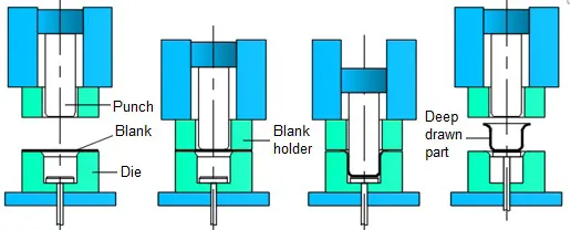
Deep Drawing Techniques:
- Hydroforming
- Hydro-mechanical deep drawing
- Aquadrawing
- Hydraulic deep drawing
- Guerin process
- Marform process.
Benefits:
- eamless parts: deep drawn parts are created from a single sheet of metal
- Rapid cycle times: large quantities of products are easily manufactured through deep drawing
- Complex axi-symmetric geometries: deep drawing delivers exceptional detailing and accuracy
- Reduced technical labor: precision deep drawing can deliver similar results as technical labor in quicker time frames.
Hemming
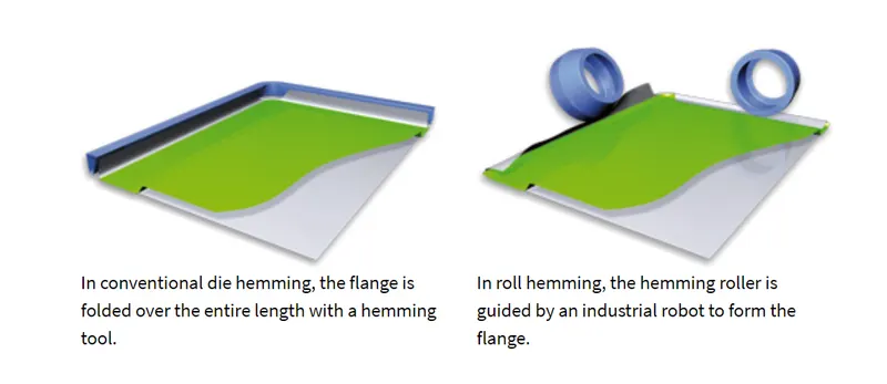
- Hemming is a forming operation in which the edges of the sheet are folded or folded over another part in order to achieve a tight fit. Normally hemming operations are used to connect parts together, to improve the appearance of a part and to reinforce part edges.
- In car part production, hemming is used in assembly as a secondary operation after deep drawing, trimming and flanging operations to join two sheet metal parts (outer and inner) together. Typical parts for this type of assembly are hoods, doors, trunk lids and fenders.
- The accuracy of the hemming operation is very important since it affects the appearance of the surface and surface quality. Material deformations, which occur during the hemming process, can lead to dimensional variations and other defects in parts. Typical hemming defects are splits or wrinkles in the flange, material overlaps in the corner areas or material roll-in. This is why it is important to use simulation tools in order to, on the one hand, better understand the hemming process and, on the other hand, significantly reduce the number of “trial and error” loops during tryout und production.
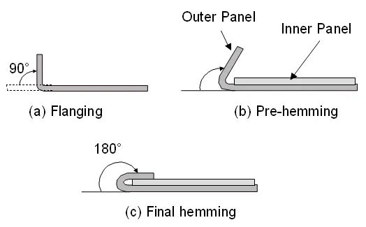
There are various types of hemming operations:
- Conventional die hemming
- Roll hemming
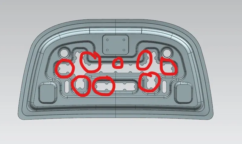
Mastic Seal
Mastic sealant can be used to either join one surface to another, or protect the area to which it is applied (cars and boats). And because it stays flexible even after it cured, it is ideal for projects requiring the joined materials (surfaces) to have some movement (glass balustrades, building joints). It works particularly well with include wood, glass, aluminium, concrete, marble, steel, and duct board. Industrial uses for this adhesive include repairing duct work in the heating and air industry. This is due to its heat resistant properties and the ability to seal and form and a strong bond, applied using a mastic sealant gun (caulking gun).
Other Applications Of Mastic
- It is for holding load-bearing walls in place.
- It is for ceiling projects, especially to eliminate the need for drywall support as it sets and dries quickly.
- It is for holding materials temporarily so the materials can be fasted, fixed, or attached by a single person working.
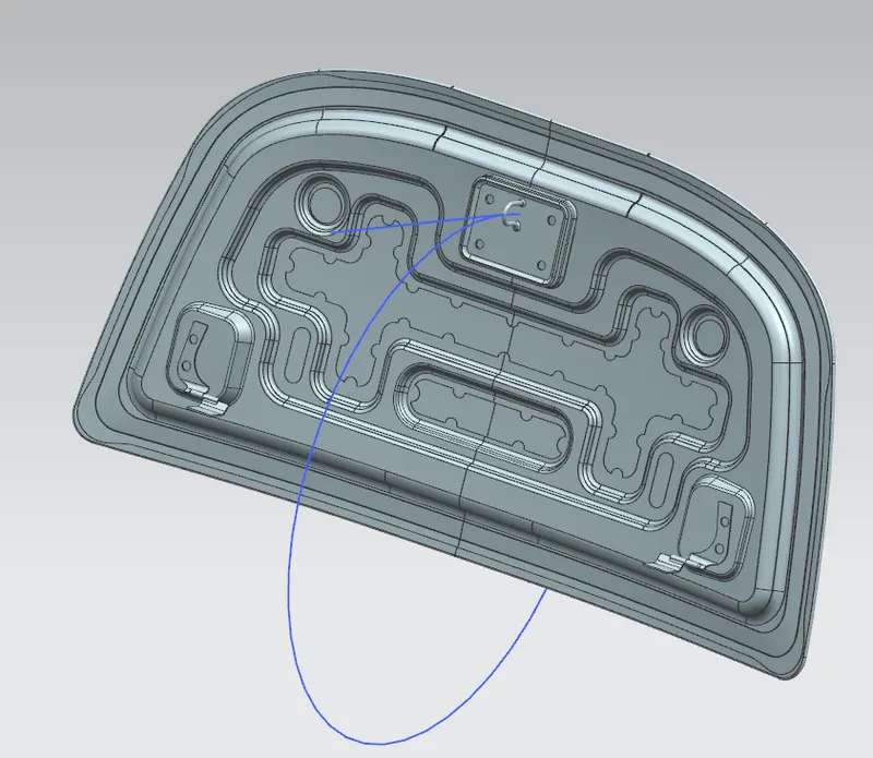
Latch Trajectory
It is the trajectory of the car hood in the car when opening and closing.
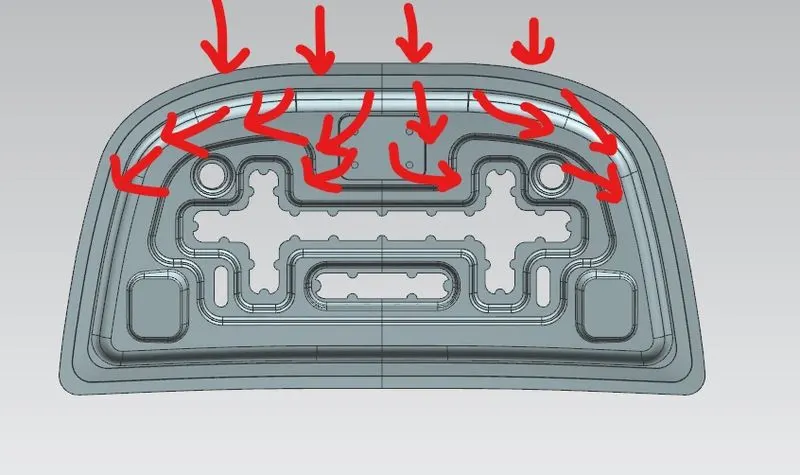
Force Distribution
In case of Impact or crash, the transmission of impact force through the Hood is controlled by designing the hood inorder to minimize the force which reaches passenger.
Reinforcements
When the part of material is removed the stiffness of the material also reduced. So Inorder to maintain the stiffness of sheetmetal the reinforments are used.
Feature Definitions
1. Extract Geometry - to create an associative or non-associative body, point, curve, or datum by extracting from existing objects.
2. Trim Body - to trim one or more target bodies using a face or plane.
3. Offset curve in face - to create offset curves on one or more faces from connected edges or curves on the surfaces. The offset curves can be associative.
4. Law Extension - to extend an existing surface or sheet based on the laws for distance and the angle of the extension.
5. Offset Surface - to create an offset of one or more existing faces.
6. Trim Sheet - to trim sheet bodies to intersecting faces and datums, and projected curves and edges.
7. Face Blend - to add tangent and curvature continuous blend faces between two or three sets of faces.
8. Projected Curve - to project curves, edges, and points onto faces, faceted bodies, and datum planes.
9. Mirror Geometry - to create associative or non-associative mirrored geometry about a specified plane.
10. Sew - to join two or more sheet bodies into a new single sheet body. If the collection of sheet bodies encloses a volume, a solid body is created.
11. Thicken - to offset one or more connected faces or sheets into a solid body.
12. Datum Coorninate System - to quickly create a coordinate system consisting of a set of reference objects.
13. Through Curves - to create a body through multiple sections where the shape changes to pass through each section.
14. Trim and Extend - This option lets you extend and trim one or more surfaces using a set of tool objects composed of edges or surfaces.
15. Edge Blend - to round sharp edges between faces.
16. Emboss - Modifies a body with faces made by projecting a section along a vector. Emboss features are useful for stiffener and locator objects.
17. Datum Plane - to create a planar reference feature to help define other features, such as swept bodies and features at angles to the faces of target solids. Datum planes can be associative or non- associative.
18. Wave Geometry Linker - to copy geometry from other parts in the assembly into the work part.
19. Extend Sheet - to extend or trim a solid or sheet body.
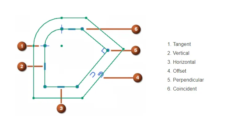
20. Geometric Constrains
Geometric Constraints Specify and maintain geometric conditions for or between sketch geometry.
For example, geometric constraints can establish:
-
A line as vertical or horizontal.
-
Two lines as perpendicular or parallel to each other.
21. Assembly Constrains
Use the Assembly Constraints command to define positions of components in the assembly. NX uses directionless positioning constraints, which means that either component can move to solve the constraint.
You can use assembly constraints to:
-
Constrain components so they touch each other or align with each other. The Touch Align constraint is the most commonly-used constraint.
-
Specify that a component is fixed in place. This is useful when you want to control which components move when the software solves a constraint.
-
Bond two or more components together, so they move together.
-
Define a minimum distance between selected objects in components.