Hood design-Week 2
AIM:
To create a hood using surface workbench and adjusting using assembly workbench.
METHODOLOGY:
Creating inner and outer hood panel.
Creating Embossments.
Creating hemming and corner relief.
Giving Thickness.
Assembling Latch and hinge.
Creating striker path using hinges centre.
Draft Analysis
PROCEDURE:
OUTER PANEL
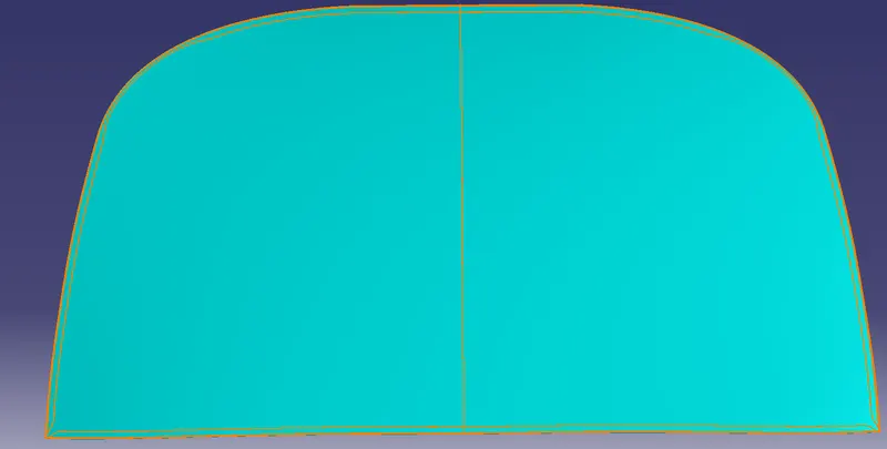
Initially, the create an outer panel by using the given surface. Split the given surface into half as it is symmetric.
Offset the surface to create a hemming portion with clearance values of 0.2.
Create a boundary on the offset surface and then use a parallel curve and split the inside surface.
Now by using a blend or multisection surface create a surface from the initial surface to the offset surface.
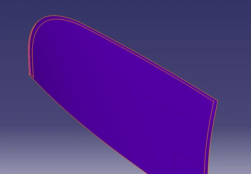
Join them by using a shape fillet of 3mm.
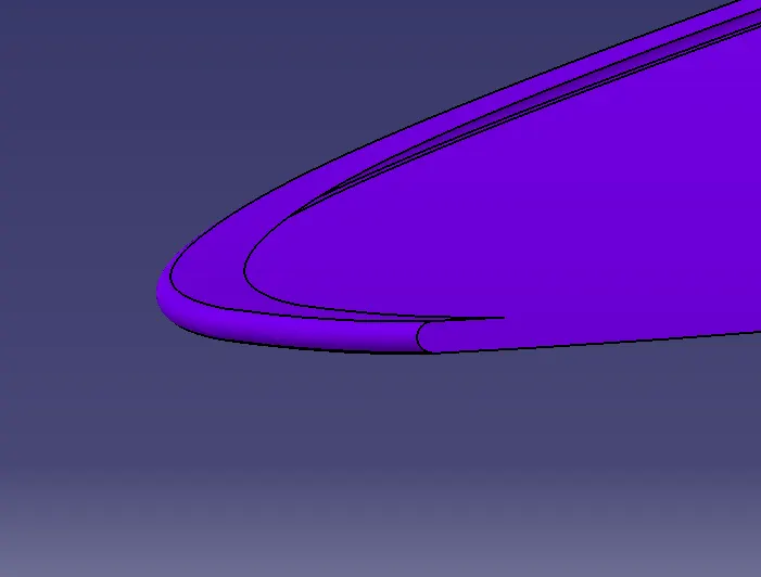
After the hemming portion is created, create a sketch for corner relief portions and split them out.
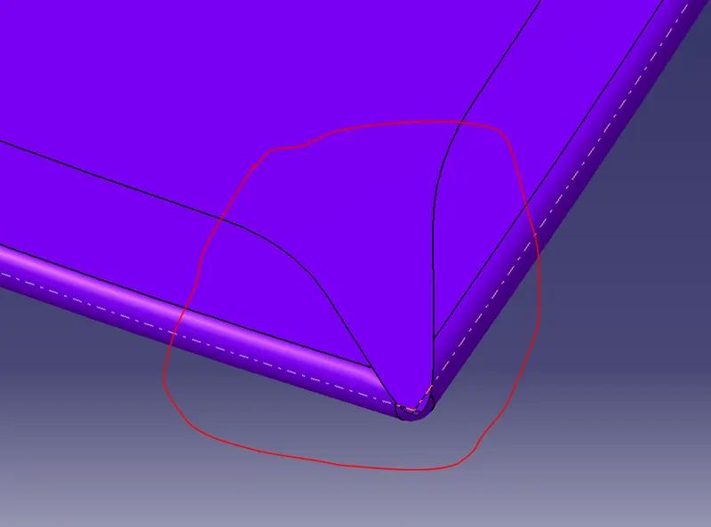
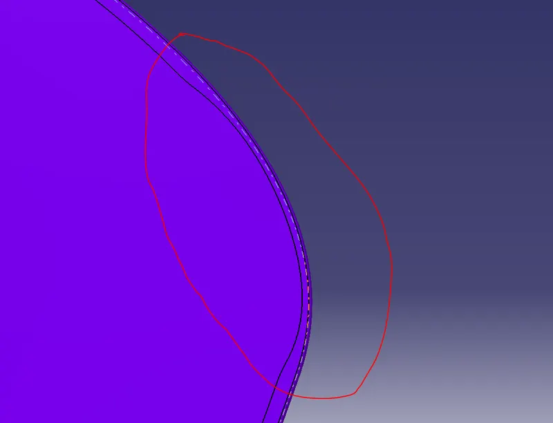
Now, create a body and thicken the surface to 0.75mm.
INNER PANEL:
For inner use, the same surface given followed by the given master section.
Initially, split the given surface into half as it is symmetric.
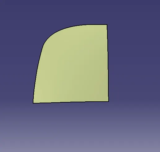
In this process offset the initial surface then split them by creating a boundary and creating a multisection or blend then shape fillet to join them.
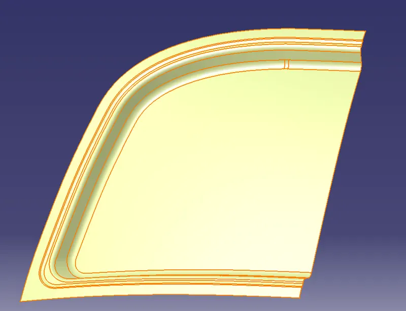
Thicken them to 1.5mm.
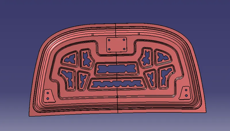
EMBOSSMENT:
To create embossments, create a sketch by offsetting the lower offset surface boundary and then creating a pattern such that while impact the force exits through the A-pillar.
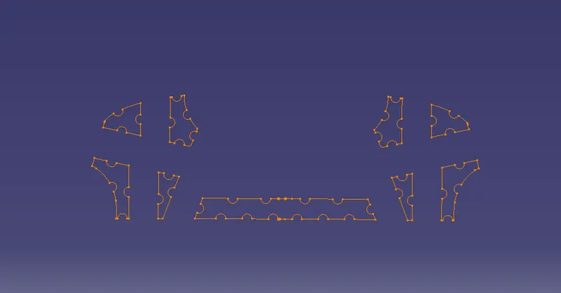
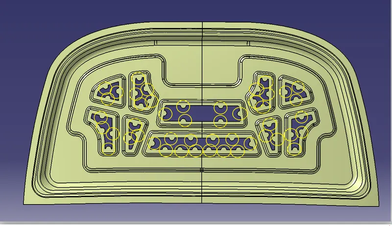
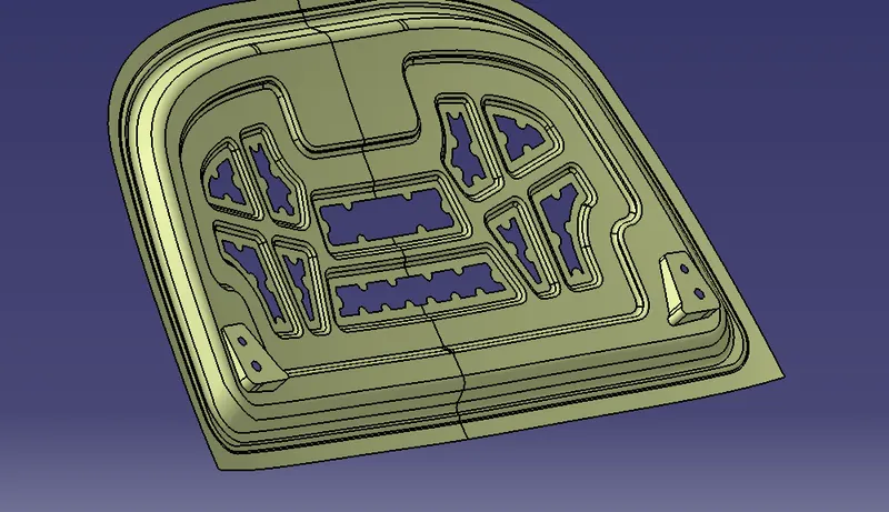
Then the same process for the embossment offset surface, split and shape fillet.
Create a cutout to reduce the weight of the hood and give mastic points.
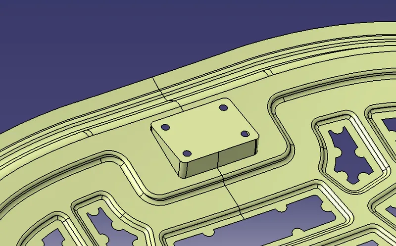
Hinge Embossment
Latch Embossment
REINFORCEMENT:
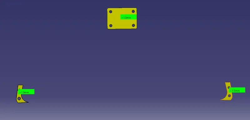
To create a reinforcement extract the portion of the hinge and latch.
Offset it to 0.75mm and then thicken it to 1.5mm.
ASSEMBLING PARTS:
Create an assembly product and insert all the parts.
Assemble them by using coincidence and offset constraint.
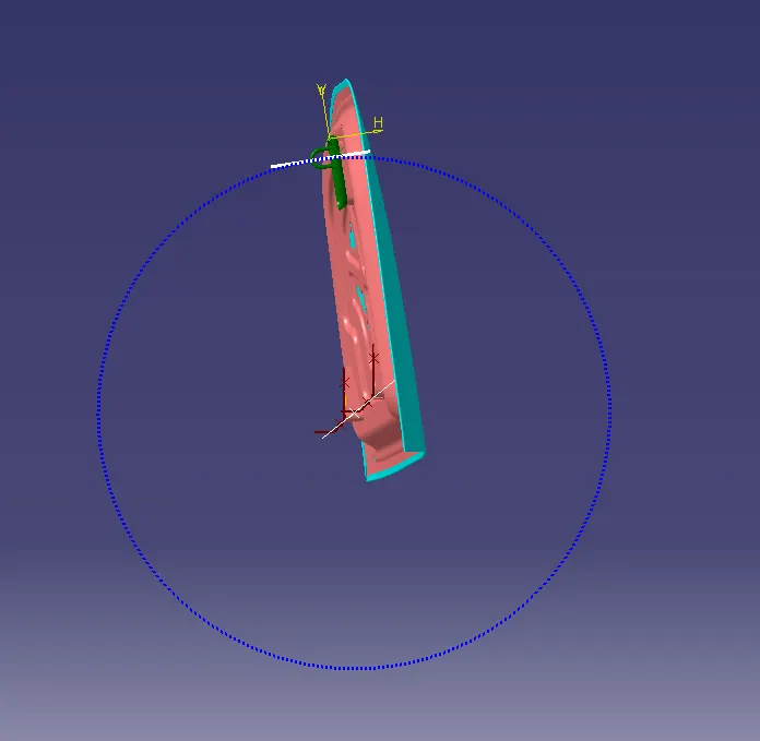
For the striker trajectory, create a line from the centre of the hinges and create a midpoint and create a circle.
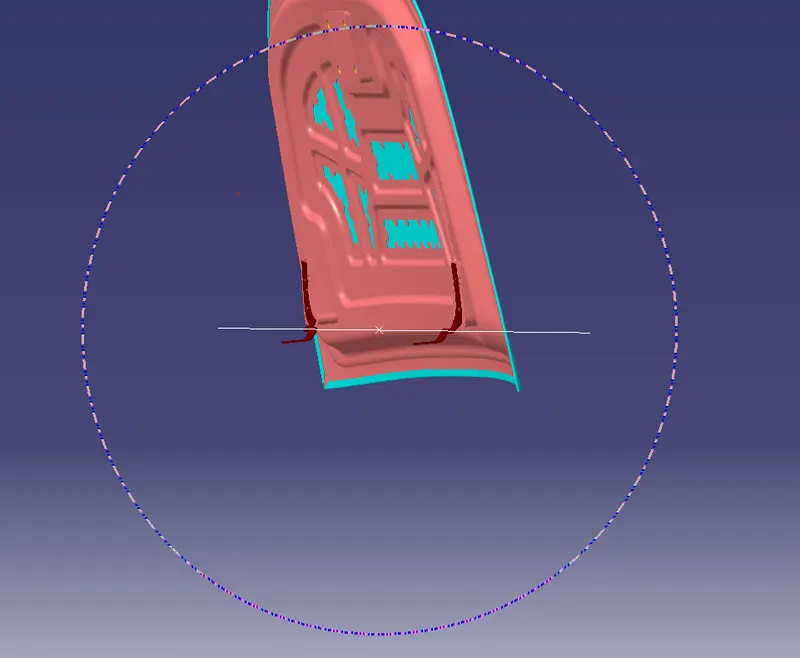
Create a tangential line for the striker.
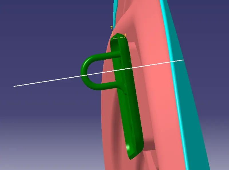
Assemble the latch such that the line should be tangent to the circle, at the striker tip.
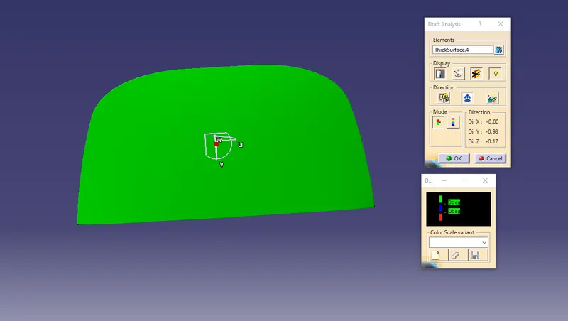
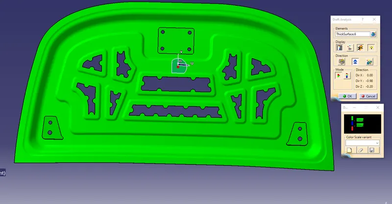
DRAFT ANALYSIS:
Outer panel
Inner panel
Introduction
Hood:
A car hood also referred to as a bonnet in some other countries is the hinged cover that rests over the engine of a front-engine vehicle. Its purpose is to provide access to the engine for repair and maintenance. A concealed latch is typically used to hold down the hood.
- The car’s hood consists of an inner and an outer panel. The inner panel provides strength, while the outer panel is just a metal cover. The underside of the hood is often covered with a sound-absorbing material.
- Hood is typically made out of steel or aluminium, although aftermarket manufacturers may manufacture hoods out of fibreglass, carbon fibre, or dry carbon.
- The hood or bonnet is the hinged cover over the engine of motor vehicles that allows access to the engine compartment for maintenance and repair. On passenger cars, a hood may be held down by a concealed latch.
- Some high-performance cars have ‘hood scoops’ which channel outside air directly to the air filter, which gives improved performance and efficiency.
- It is a hinged thin sheet that covers and protects the main parts of a car-like engine. Its main function is to direct access to the engine, battery and other crucial parts of the cars for repair and maintenance and to protect these parts from direct sunlight and dust. It also gives good looks and helps to design car aerodynamically stable.
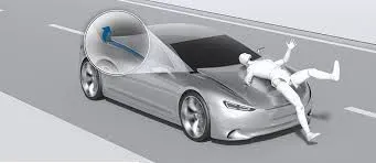
- Regulations have come into effect in recent years that place a limit on the severity of pedestrian head injury when struck by a motor vehicle. This is leading to more advanced hood designs.
- The hood release is a small lever, which is usually mounted under the dash. It is connected to the hood latch by a cable.
- The hood latch has a safety feature, which requires a second latch to be released before the hood will open. This is to prevent accidental opening while driving.
Corner Relief:
In sheet metal, a bend relief is an incision cut along the sides of a planned bend. Though bend relief lengths and widths vary between projects, they all share a common goal: preventing tearing and part deformation during the bending process.
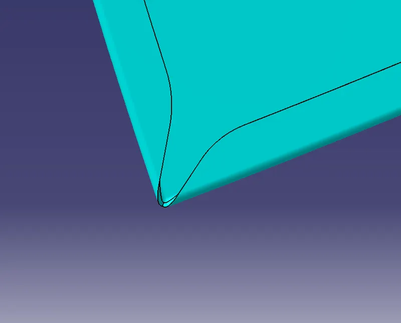

During the bending of sheet metal, the material around the bend tends to stretch and deform. The metal between a bend and a flat surface, if there is any, tends to stretch and tear as the bend is created, which results in a deformed and structurally weak component. A bend relief creates space between the bent and unbent surfaces so that the edge of the sheet metal is perpendicular to the bend itself. The gap between the bend and surrounding material allows us to shape the sheet in the press brake cleanly, eliminating cracking and tearing.
Because a bend relief serves a simple purpose, you can choose its shape to meet the needs of your design. Common bend relief shapes include rectangular and obround. At a minimum, the size of the bend relief should equal the material thickness plus the inside bend radius.
When you add relief, sheet metal sections are removed from the model. You can apply for corner relief automatically to all corners or manually to individual sets of corners. Relief helps to control sheet metal material behaviour and to prevent unwanted deformation during unbend operations.
Hemming:
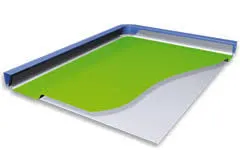
It is a technology used in the automotive industry to join inner and outer closure panels together (hoods, doors, tailgates, etc.). It is the process of bending/folding the flange of the outer panel over the inner one.
It is forming operation in which the edges of the sheet are folded or folded over another part to achieve a tight fit. Normally hemming operations are used to connect parts, to improve the appearance of a part and to reinforce part edges.
In-car part production, hemming is used in assembly as a secondary operation after deep drawing, trimming and flanging operations to join two sheet metal parts (outer and inner) together. Typical parts for this type of assembly are hoods, doors, trunk lids and fenders.
The accuracy of the hemming operation is very important since it affects the appearance of the surface and surface quality. Material deformations, which occur during the hemming process, can lead to dimensional variations and other defects in parts. Typical hemming defects are splits or wrinkles in the flange, material overlaps in the corner areas or material roll-in. This is why it is important to use simulation tools to, on the one hand, better understand the hemming process and, on the other hand, significantly reduce the number of “trial and error” loops during tryout and production.
There are various types of hemming operations:
- Conventional die hemming
- Roll hemming
Conventional die hemming
It is suitable for mass production. In die hemming, the flange is folded over the entire length with a hemming tool. Normally the actual hemming is a result of a forming operation in which the flange is formed with a hemming tool after the drawing and trimming operations have been completed. The formed flange is then hemmed in several process steps. These steps include, for example, the pre-hemming and final hemming depending on the respective opening angle of the flange. Production plants for conventional die hemming are very expensive, but the cycle times are very low.
Roll hemming
It is carried out incrementally with a hemming roller. An industrial robot guides the hemming roller and forms the flange. Roll hemming operation can also be divided into several pre-hemming and final hemming process steps. Roll hemming is very flexible to use and tool costs are significantly lower as compared to those of conventional die hemming. However, the cycle times are much higher since the hemming is realized using a hemming roller that follows a defined path.
Pedestrian safety:
Many pedestrian crashes involve a forward-moving car (as opposed to buses and other vehicles with a vertical hood/bonnet). In such a crash, standing or walking pedestrian is struck and accelerated to the speed of the car and then continues forward as the car brakes to a halt. The pedestrian is impacted twice, first by the car and then by the ground, but most of the fatal injuries occur due to interaction with the car. Vehicle designers usually focus on understanding the car-pedestrian interaction, which is characterized by the following sequence of events: the vehicle bumper first contacts the lower limbs of the pedestrian, the leading edge of the hood hits the upper thigh or pelvis, and the head and upper torso are struck by the top surface of the hood and/or windshield.