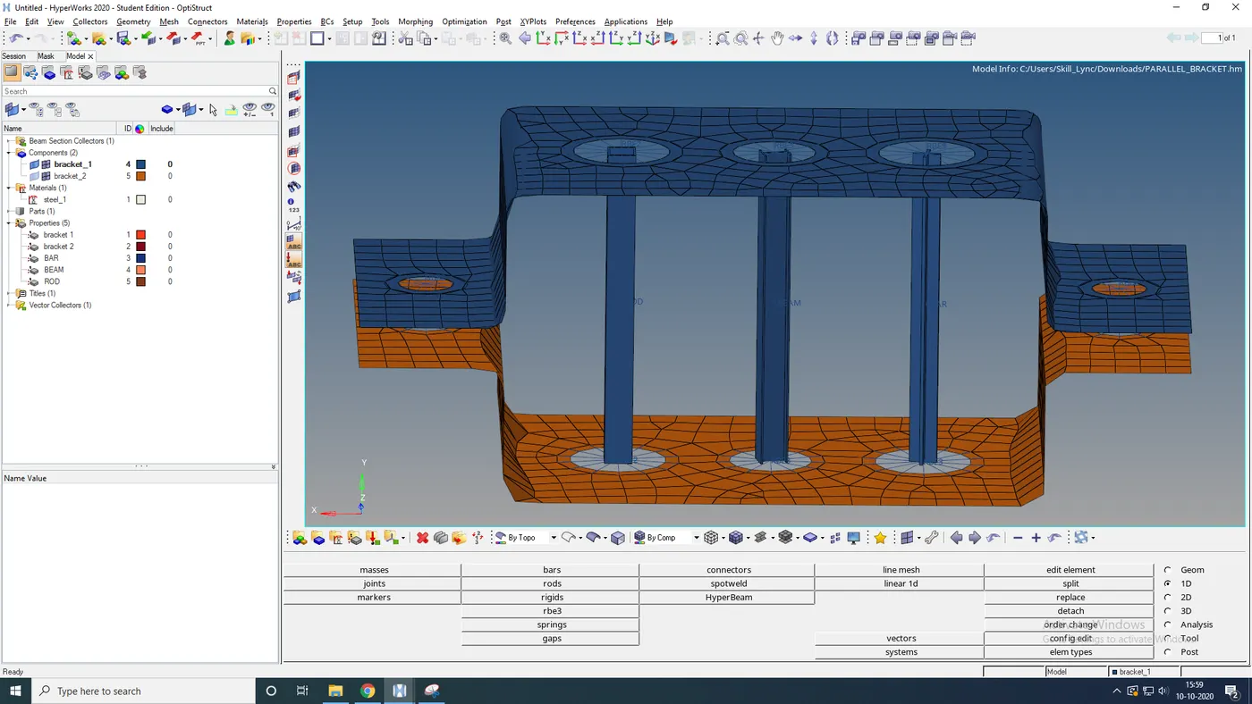
Week 4- Challenge
Aim: To create a 1D element with the following component with given cross-section and DOF.
Software: Hypermesh.
Procedure:
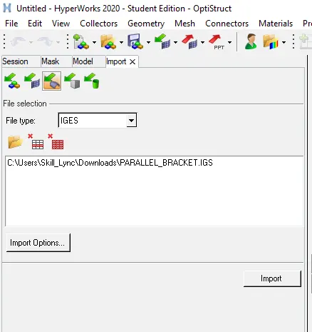
Open the software and import the model by selecting "geometry", file as "iges".
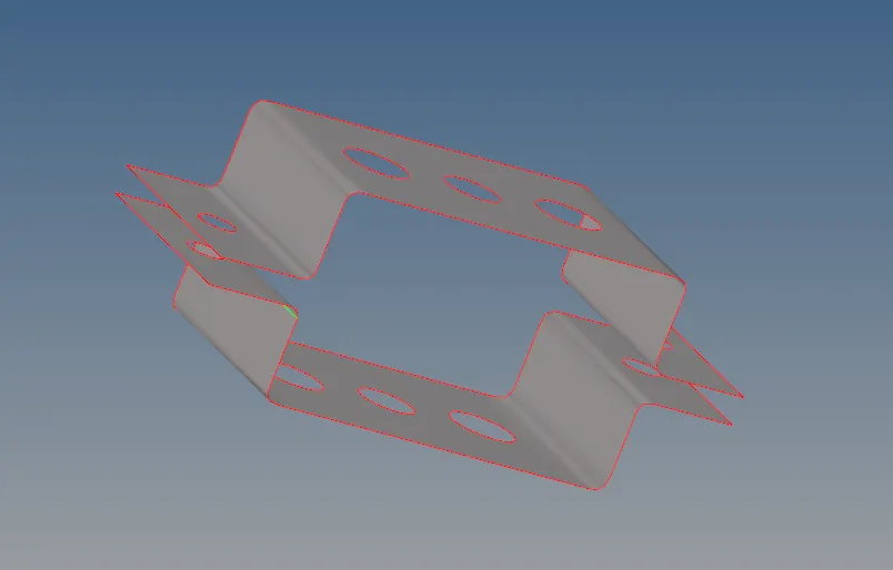
After importing the model create midsurfaces by selecting the "midsurface" option by clicking on the surface of the model.
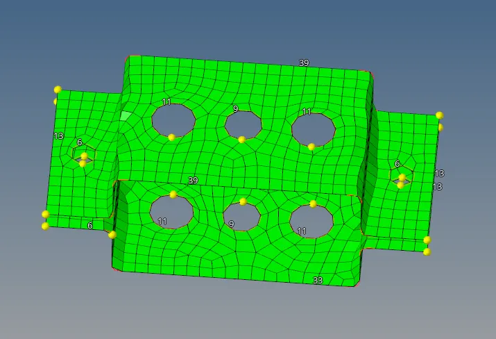
Now goto "2D" then select "automesh" and mesh the model.
After meshing we need to create different elements like rod, beam & bar.
ROD element(HOLE A)
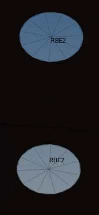
Goto "1D", select "rigid", select "calculate nodes" set as "path", then "multiple nodes". Select the nodes on the model (hole a) uncheck "dof1,2&3" for translational movement then create it.
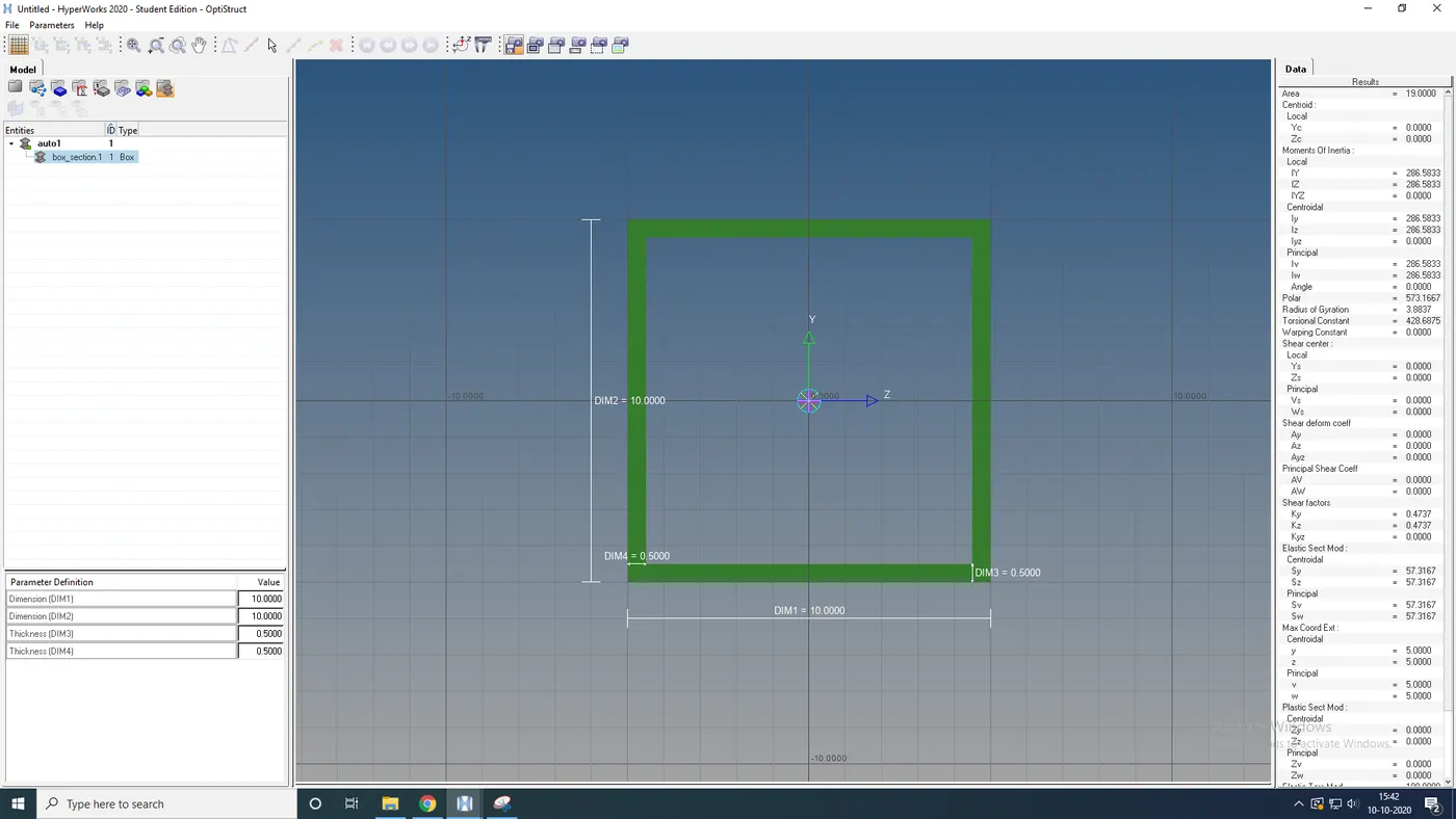
Now open "Hyperbeam", select "standard section", select "optistruct", select "box", then create. It will open new Hyperbeam window set the "Dimension a= 12 mm, dimension b=10 mm & Thickness t= 0.75 mm" rename it as box and then return to the "model bar".
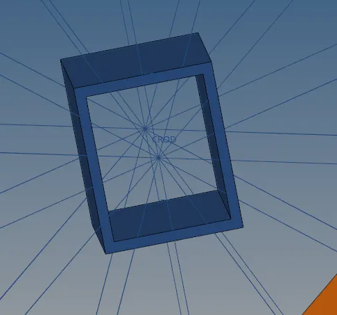
Goto "rods" and select the two nodes between the rigid points, Select "element" as "CROD" and create. Then add the "property" "Box" in the "CROD".
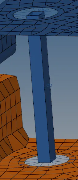
BEAM element(HOLE B)
Now for hole b, goto "1D", select "rbe3", select all the nodes on hole b by press "shift+left click", and create.
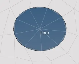
Similarly go to "Hyperbeam" and select "hyperbeam", select "I-Section" then create. After setting the "dimension a= 8 mm, Dimension b= 10 mm, Dimension c= 8.5 mm, Thickness t1= 0.75 mm, Thickness t2= .6 mm & Thickness t3= .6 mm", rename it as "Beam" and then return to the model bar. Then add the "property I-section" in the "CBEAM".
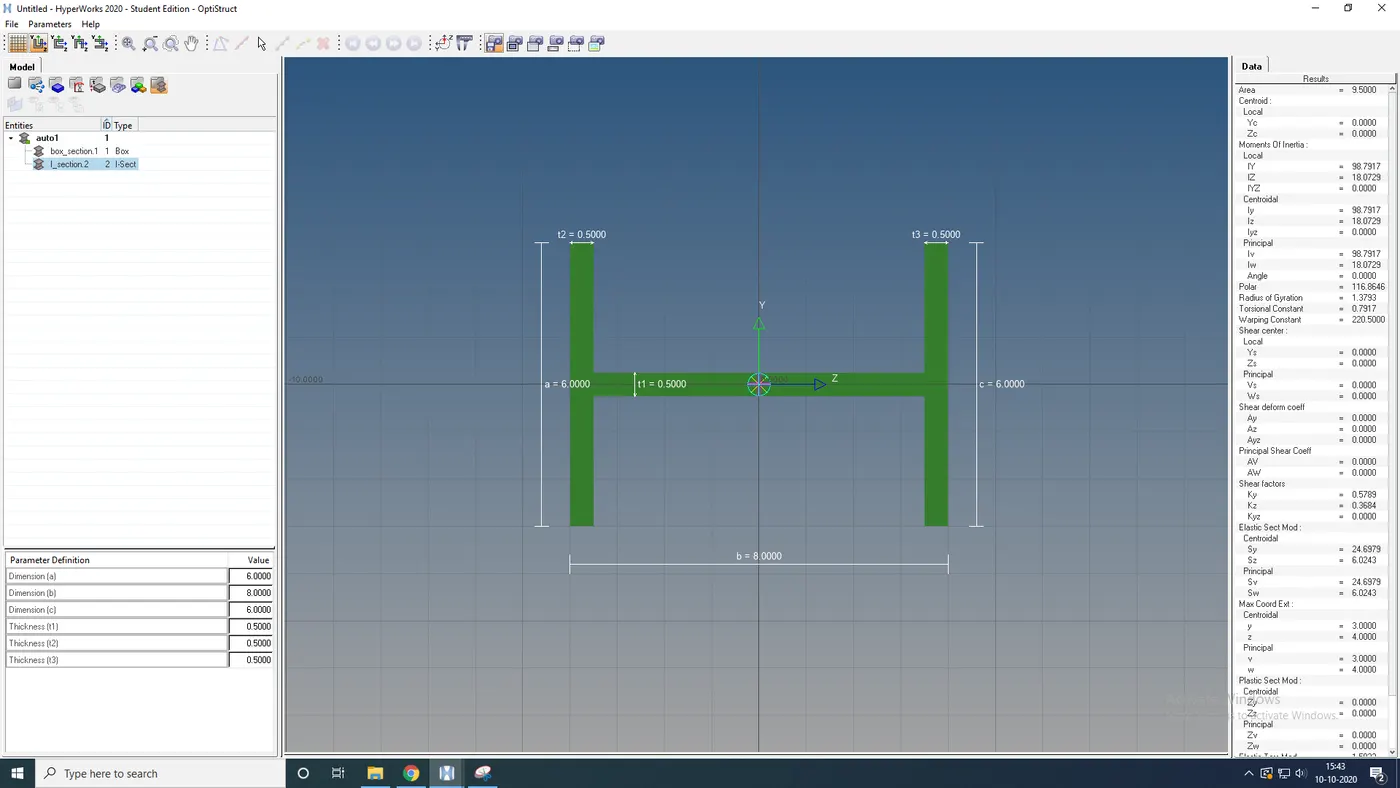
Goto "bars" and select "nodes A & B" set the "vector", select "element type" as "CBEAM" and "property" as "Beam".
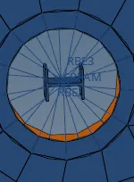
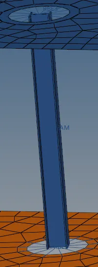
BAR element(HOLE C)
Again goto "1D", select "rbe3", uncheck "DOF1 & 2", select all the nodes on hole b by press "shift+left click", and create.
Goto "hyperbeam" and select "Optistruct", select "cross-section", then create. After setting the "dimension DIM1= 5 mm, Thickness DIM2= 1.2 mm, Dimension DIM3= 10 mm & Thickness DIM4= 1.2mm", rename "Bar" and then return to the "model bar".
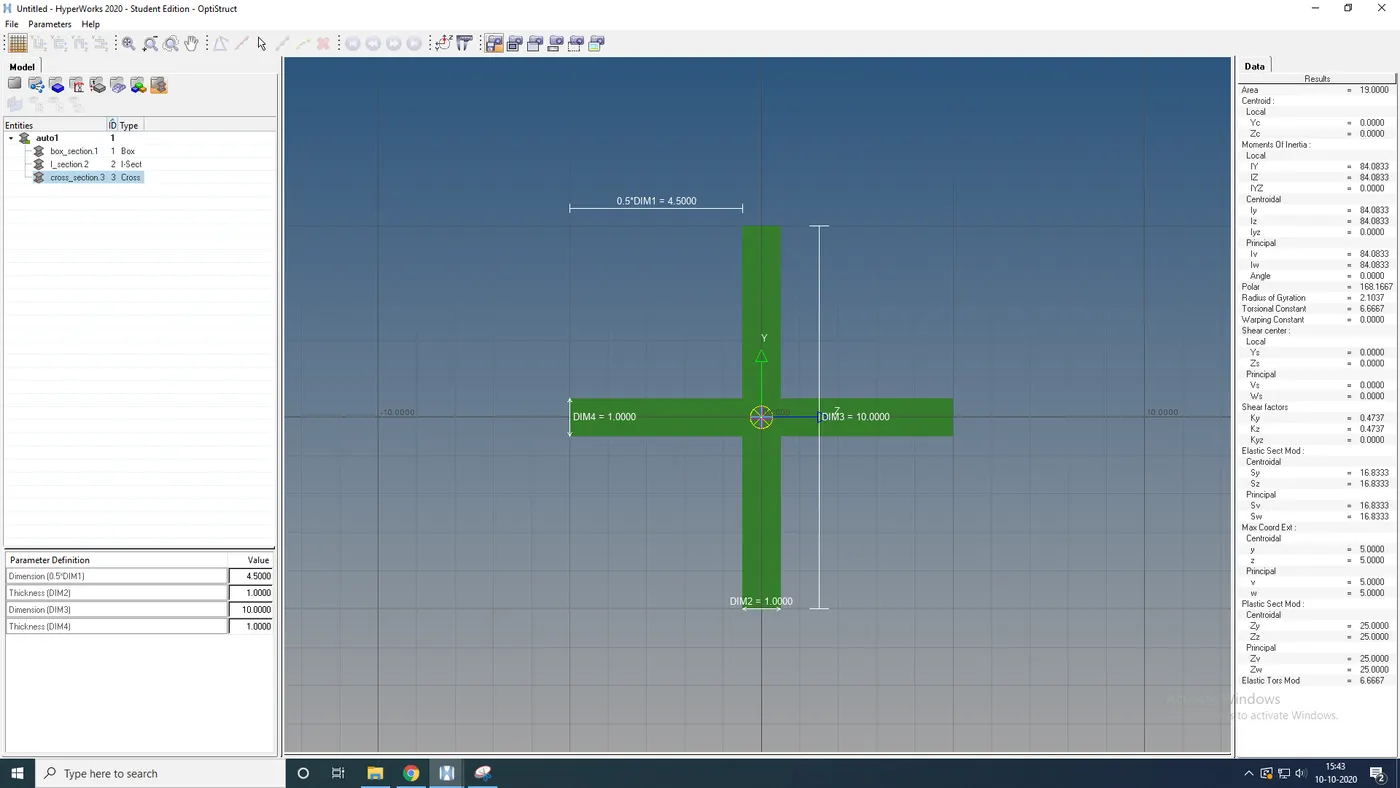
Goto "bars" and select "nodes A & B" set the "vector", select "element type" as "CBAR" and "property" as "Bar". Then add the "property" as "Cross-section".
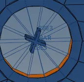
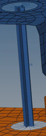
Now for hole D & E goto "1D", select "rbe3", select all the nodes on hole b by press "shift+left click", and create.
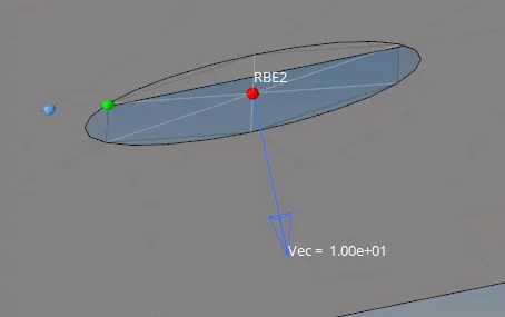
Now select "vector", add the "magnitude" to "10" and set the "vector" nodes and create.

For spring element just goto "spring", select nodes then element as "CELASI1" and create.

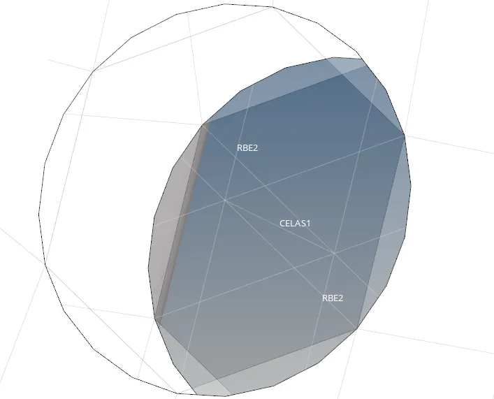
Result: The model is created with given dimensions, cross-sections and DOF.