Hood design-Week 2
Design Hood Outer Panel, Inner Panel and the necessary reinforcements by following the Master Section.
What is an automotive car Hood
In general terms, a hood is a cover for engine compartment and connected elements, it is hinged to the car body to act like a door for open and close positions.
It is not as simple as it looks, there is more to it than meets the eye. The design of a hood involves not only the mechanical properties and behaviour regarding maintaining the strength of the car but also includes the pedestrian safety aspects.
Factors to consider for designing of hood
(i) Hood open angle
(ii) Hood balancer
(iii) NVH (Noise Vibration Harshness) reduction
(i) Hood open angle & Head Zone limits
Open angle ( hood opened position) or head zone is the space available for the person for easy access to the engine compartment. Open angle should always be ample enough so that the person can easily access the engine compartment without any head injury. The opening angle is decided based on the average person height in a country. For eg: the opening angle for hood or head zone limit is more for countries like USA and Europe and less for Asian countries like Japan. This is due to the reason that average height of a person in USA & Euproe is 6ft and in Japan is below 6ft.
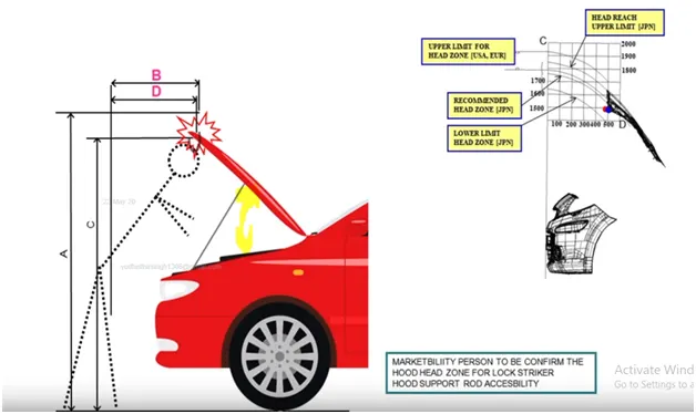
From the above figure plot, it can be seen that the head upperlimit or full open angle is more for USA and Europe and less for Japan.
(ii) Hood balancer
Hood balancer is a device for supporting the engine hood of a motor vehicle in its open position. There are two types of hood balancers.
Importance of hood balancer is that it can decide the open angle of the hood i.e., if the hood balancer length is more, more is the open angle and if the hood balancer length is less, less is the open angle.
(a) Support rods
(b) Gas stays
(a) Support rods are slender columns that can be easily mounted or unmounted either from the hood or engine compartment while opening and closing of the hood.
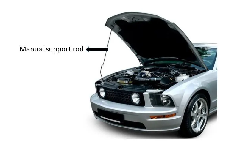
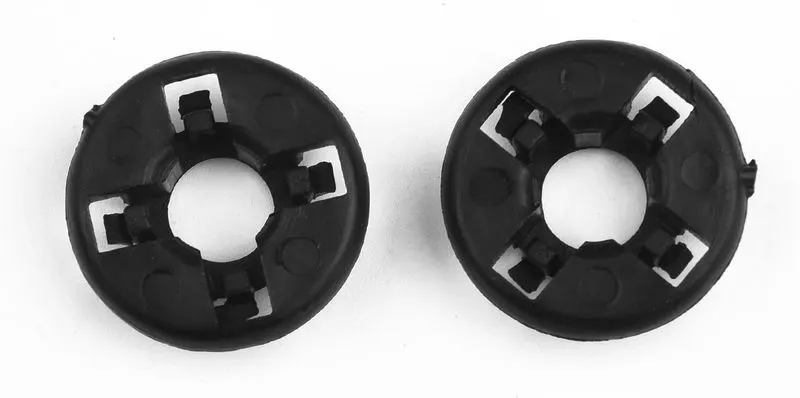
Support rods are mounted using gromets. Gromets are provided on both sides hood and as well as engine compartment
Placement & Positioning of support rods
Placement is crucial as the vibrations due to engine and also the vehicle motion shoud not effect the support rod. The support rods are placed in a position where there is proper clearance with its surrounding components.
Positioning of support rod should be in such a way that it should not hamper the fixing and removal of components in the engine compartment. For eg hood when it s open position, the support rod should not be an obstacle in placing and removing the battery of the car.
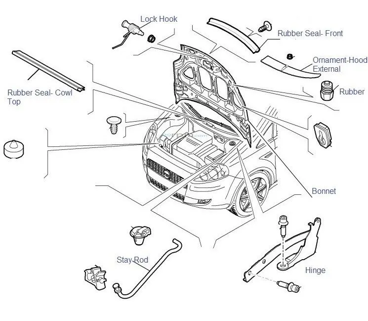
From the above figure, it can be seen that the stay rod or support rod is positioned to extreme right , this positioning is apt as it does not create any hassle for access to components in the engine compartment.
Design of support rod
The support rod is designed in such a way that it has certain curvature or bends. This aids in providing strenght to the hood balancer with out any failure. The bending radius should not exceed 35mm.
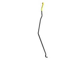
From the above figure, it can be seen that the suppor rod's shape is bent for better funtionality without failure.
(b) Gas stays
Gas stay is another type of hood balancer that has a semi automatic feature. It requires an initial force to be applied while opening the hood and the rest of the movement is automatic in nature. Gas stay comprises piston with narrow perforation, cylinder and compressed nitrogen gas. The ends of the gas stay are mounted on ball studs. The gas stay is an additional component on the hood and engine compartment, therefore, a bracket is placed before ball studs as a reinforcemnt to provide localised strength.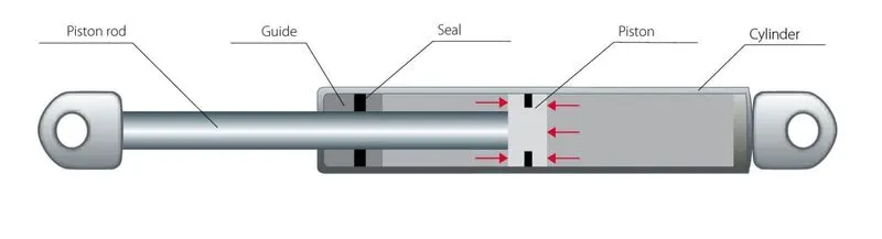
Gas stay mechanism
The above figure represents the piston cylinder mechanism of a gas stay. The left side end of the gas stay is mounted on the engine compartment and right side end of the gas stay is mounted on the hood. The piston cylinder movement occurs by means of force balance mechanism. As observed from the figure, the forec acting from right to left is more compared to left to right, this is due to availability of more on piston from left of right, therefore more force (Pressure X Area) while opening the hood.
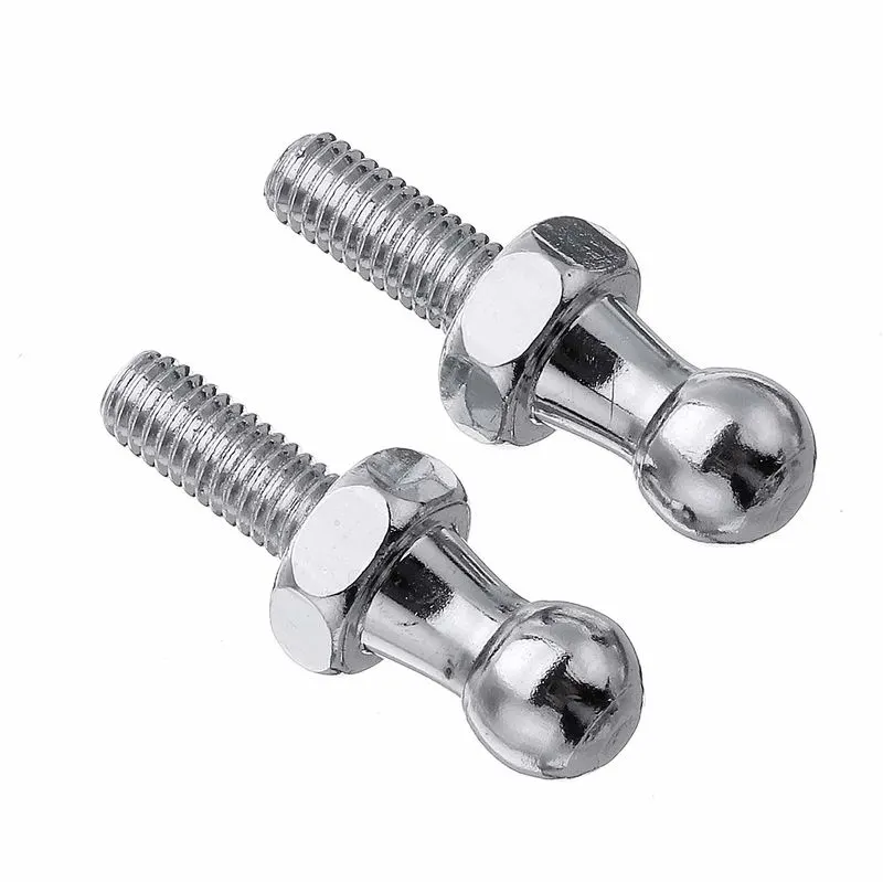
Ball studs for mounting
Brackets as reinforcement
(iii) NVH (Noise Vibration Harshness)
NVH on the hood occurs due to engine vibrations and vehicle motion. To reduce NVH, stiffener pad(acts as a reinforcement) is sandwiched between outer and inner panels.
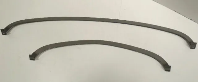
Stiffener pad
Mastic sealant is also applied between outer and inner panels to reduce NVH. Mastic sealant is a glue that bonds outer and inner panels and also provides localised strength. It is applied at gaps 0f 5mm between outer and inner panels. The mastic sealant s applied as drops and each drop covers a dia of 80mm around it.
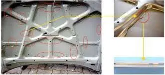
Mastic Sealant points
DESIGN OF HOOD ASSEMBLY USING NX CAD
COMPONENTS OF HOOD
1) OUTER HOOD PANEL
2) INNER HOOD PANEL
3) HINGE ASSEMBLY
4) STRIKER
5) REINFORCEMENT
DESIGN OF HOOD ASSEMBLY USING NX CAD
1) Outer hood panel
Function:
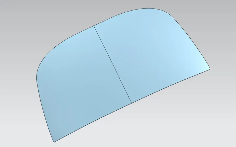
It acts as a protective cover for engine compartment and is the aesthetic part of the car (Class A surface). The thickness of outer hood panel is 0.75mm and the material used in general is steel or aluminium.
Given part file of outer hood panel is as follows
2) Inner Hood Panel
Function:
Inner panel acts as a reinforcement to outer hood panel. The inner panel consists of embosses and voids in its structure. The embosses are designed in such a way that the the force transmission direction is towards the hinges. The voids in the inner panel are created to reduce the stiffness of the hood. The reduction in stiffness is considered for pedestrian safety, i.e., when a pedestrian hits his head on the hood, he suffers a minimum injury or no injury and is safe. The hood design focuses more on distribution of energy in situations of an accident (if pedestrian gets hit) and no possibilities of localised impacts or forces. The thickness of inner hood is 0.75mm and is in general made of aluminium and steel.
Design of inner hood panel
-An assembly file is created in NX CAD
-The Outer Panel part file is added into assembly
-New file is created for Inner hood panel in the assembly environment
-To develop inner hood panel, the Outer panel is mimicked using wave geometry linker. Now, the outer panel is hidden and this linked face is used as reference to create inner hood panel.
-By refering the given master section, the inner hood panel is created.
-First offet surface is created using offset surface (1.7mm), offset curve on face at 20mm from boundary and sheet is trimmed to retain smaller surface.
-Second offset surface is created (4mm), offset curve on surface at 22mm from boundary and sheet trimmed retaining the larger surface.
-Third offset surface is created (25mm), offset curve on surface at 50mm from boundary and sheet trimmed retaining the larger surface.
- Law extension is applies on the third surface boundary at a draft angle of 38 degree w.r.t vertical (the inner panel is manufacured using deep drawing process) and is extended beyond the second surface. Trim and extend is to trim and join the second and thrid surfaces.
- Through curves is used to fill the gap between first surface and second surface.
- The surface are joined and filleted using face blends.
Emboss Definitions
- Embosses are created for force transmission towards hinges and also for provision of more number of mastic seal points for adhering outer and inner hood panels to reduce NVH. Mastic seal can be applied in areas where the distance between outer hood panel and inner hood panel is less or 5mm and this can achived using embosses.
- Embosses are created using sketch, offset curve on face and filleted at the edges, the embosses are not created near the striker and hinge region.
- Voids are created to reduce the stiffness of the overall hood assembly so that the pedestrian suffers a minor injury in situations of an accident.
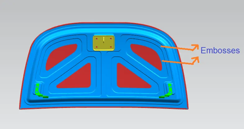
Emboss Definitions
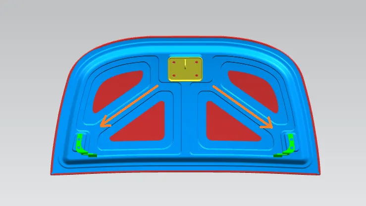
Force transmission towards hinges
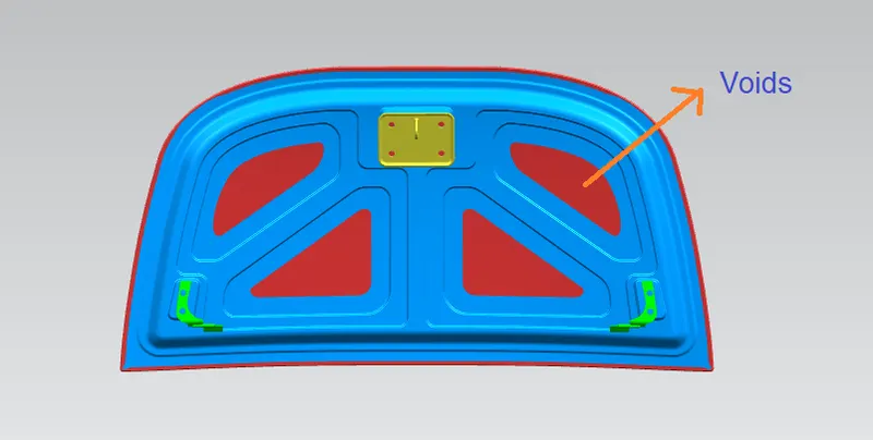
Voids
3) Assembly of Hinges
- Go to Inner hood panel interface (double click or make a work part), a datum plane parallel to hood surface is created and sketch for hinge emboss is created.
- Go to Assembly interface(select or double click on entrire assembly), add the hinge assembly to the assemby interface.
- Provide toch assembly constraints from hinge face to hinge emboss face and constraint the hinge axis parallel to x axis.
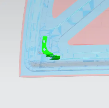
- Mirror the geometry about YZ plane and sew the surfaces.
- Mirror hinge assembly onto the other hinge emboss.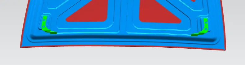
4) Assembly of striker using Latch trajectory
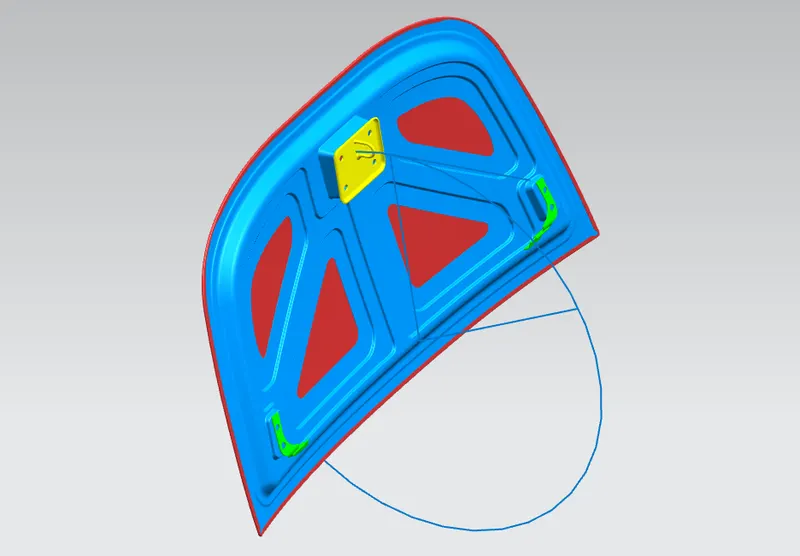
The striker is positioned along the trajectory that forms a circle with midpoint of hinge axis as centre.
- The hinge axis is created by creating line with end points. A midpoint on hinge axis is created and a circle is generated with midpoint as centre. The circle passes through the striker region for better alignement of striker during assembly. Create a tangent line perpendicluar to the radial line created at an angle to striker region.
- Add the striker to the assembly interface, go to striker interface (make work part), create a line passing through the centre of the latch.
- Go to assembly interface (select or double click on entrire assembly), align the end point of striker latch centre line to the intersection point of circle radial line and its tangent.
- Now align the centre line of latch to the tangent line of circle or trajectory.
- After positioning the striker, go to inner hood panel, create a linked face of striker rear using wave geometry link and create an emboss using linked face with law extension.
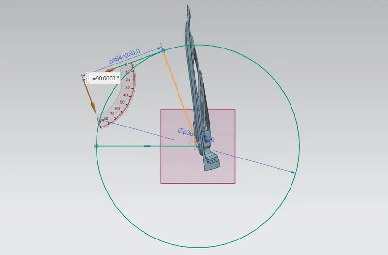
Latch trajectory
Striker Positioning
5) Reinforcements
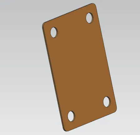
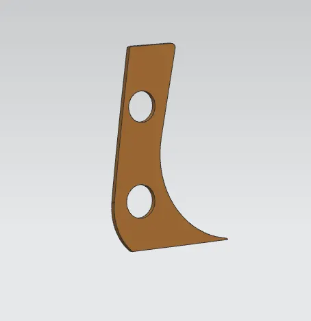
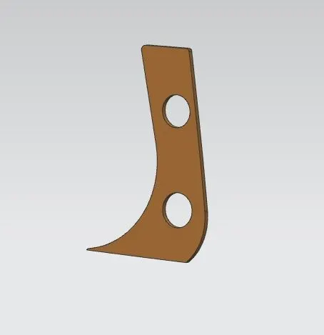
As the components get assembled on the hood, the strength of the hood reduces in the assembly regions, therefore, to compensate for the loss of strength, reinforcements are added, the thickness of the reinforcements is 1.5mm.
 Striker reinforcement Hinge reinforcements
Mastic seal points
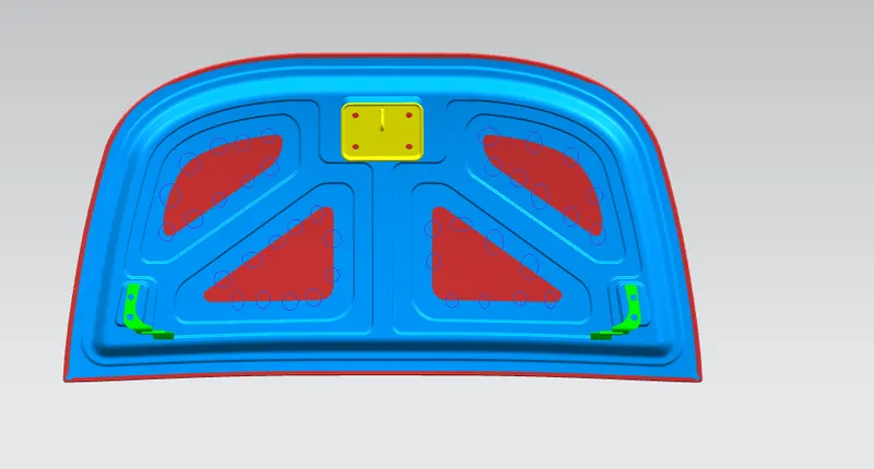
Mastic Seal is applied is regions where the distance between outer panel and inner panel is least ( 5mm ), mastic seal glues the inner and outer panel reduces the NVH of the Hood.
Manufacturing process for Car Hood panels
(i) Deep drawing process
Deep drawing is a sheet metal froming process used for manufacturing inner and outer panels of the car hood.
Deep drawing of sheet metal is performed with a punch and die. The punch is the desired
shape of the base of the part, once drawn. The die cavity matches the punch and is a little
wider to allow for its passage, as well as clearance.
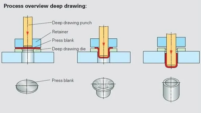
Deep drawing process
Two main factors will cause the punch in deep drawing to draw the metal into the die cavity, rather than shearing it.
One major factor in deep drawing is the die corner radius and the punch corner radius.When cutting sheet metal, the punch and die edges do not have a radius. Sharp corners onthe punch and die cause it to cut. In deep drawing process, a radius on an edge will change the force distribution andcause the metal to flow over the radius and into the die cavity. The other major factorcausing the punch to draw the sheet metal and not cut it, is the amount of clearance. Clearance in cutting operations is relatively small, usually 3% to 8% of sheet metal thickness. In deep drawing manufacture, if the clearance is too small the sheet may be cut or pierced, (not well), despite the radius. Clearance in deep drawing manufacture is greater than sheet thickness, usually clearance values are 107% to 115% of sheet thickness.
The 3D CAD models of inner panel die and outer panel die are as follows
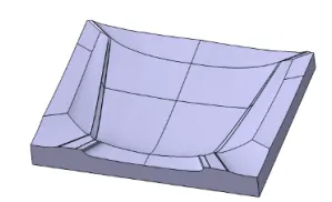
3D CAD model - Outer panel mould or die
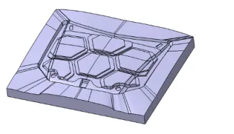
3D CAD model - Inner panel die or mould
(ii) Hemming process
Hemming is used in the automotive industry to join two sheet metal panels by bending the flange of the outer panel over the inner one.
hemming operation is perfromed using multiple rollers at different edges of outer panel. The rollers are made to roll over the sheet many times. Each pass would bend the outer panel to certain angle gradually creating a hem with desired bend radius (0.5 or equal to outer panel sheet thickness) at the final hemming stage.
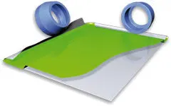
Hemming process
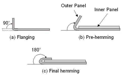
Stages of hemming process
Springback phenomenon
When producing a part, either by deep drawing, stretch forming or bending, flat sheet is transformed into a design shape and dimension. At the end of the forming process, when the part has been released from the forces of the forming tool, there is a distortion in the shape and dimension of the formed part. This distortion is termed springback.
Springback occurs at the corner regions of the outer panel while hemming. Therfore, a relief is provided at the corner regions (front and rear regions), rollers do not pass to bend the flange in these regions.
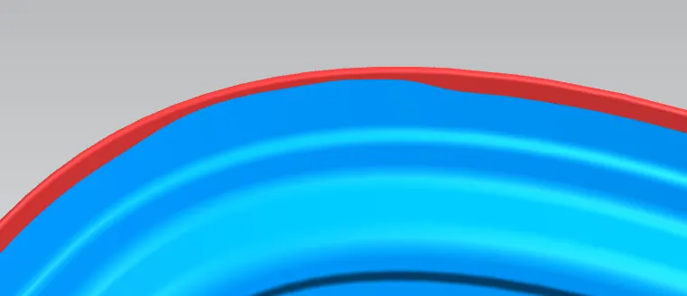
Front relief

Rear relief