Gear box Sloshing Effect using ANSYS Fluent
Introduction
Dynamic Meshing
In ANSYS Fluent the dynamic mesh capability is used to simulate problems with boundary motion, such
as check valves and store separations. The building blocks for dynamic mesh capabilities within ANSYS
Fluent are three dynamic mesh schemes, namely, smoothing, layering, and remeshing. A combination
of these three schemes is used to tackle the most challenging dynamic mesh problems. However, for
simple dynamic mesh problems involving linear boundary motion, the layering scheme is often sufficient.
For example, flow around a check valve can be simulated using only the layering scheme.
Check valves are commonly used to allow unidirectional flow. For instance, they are often used to act
as a pressure-relieving device by only allowing fluid to leave the domain when the pressure is higher
than a certain level. In such a case, the check valve is connected to a spring that acts to push the valve
to the valve seat and to shut the flow. But when the pressure force on the valve is greater than the
spring force, the valve will move away from the valve seat and allow fluid to leave, thus reducing the
pressure upstream. Gravity could be another factor in the force balance, and can be considered.
Fluid Sloshing
In fluid dynamics, slosh refers to the movement of liquid inside another object (which is, typically, also undergoing motion). The liquid must have a free surface to constitute a slosh dynamics problem, where the dynamics of the liquid can interact with the container to alter the system dynamics significantly. Important examples include propellant slosh in spacecraft tanks and rockets (especially upper stages), and the free surface effect (cargo slosh) in ships and trucks transporting liquids (for example oil and gasoline). However, it has become common to refer to liquid motion in a completely filled tank, i.e. without a free surface, as "fuel slosh".
Liquid sloshing strongly influences the directional dynamics and safety performance of highway tank vehicles in a highly adverse manner. Hydrodynamic forces and moments arising from liquid cargo oscillations in the tank under steering and/or braking manoeuvres reduce the stability limit and controllability of partially-filled tank vehicles. Anti-slosh devices such as baffles are widely used in order to limit the adverse liquid slosh effect on directional performance and stability of the tank vehicles. Since most of the time, tankers are carrying dangerous liquid contents such as ammonia, gasoline and fuel oils; therefore stability of partially-filled liquid cargo vehicles is very important.
The efficiency of gear transmissions is an important study object in the field of energy‐saving.
The total energy losses in splash‐lubricated gearboxes are mainly categorized in two ways the first
are load dependent losses, which are a result of the inter‐tooth meshing friction of gears and
inter‐surface friction of bearings and seals; the second category are independent of load and are
known as churning power losses, which are losses due to the fluid resistance torque between the
gear and the surrounding oil. When the rotational speeds of the gear speed is low, churning losses
represent a tiny proportion of the total energy losses and can generally be ignored; however, several
researchers have pointed out that when the gears rotate at higher speeds, the influence of the
churning losses increases significantly
So we can conlclude that fluid sloshing is bad.
User Defined Functions (UDF)
A user-defined function, or UDF, is a function that we program that can be dynamically loaded with the ANSYS FLUENT solver to enhance the standard features of the code. For example, we can use a UDF to define our own boundary conditions, material properties, and source terms for our flow regime, as well as specify customized model parameters (e.g., DPM, multiphase models), initialize a solution, or enhance postprocessing.
UDFs are written in the C programming language using any text editor and the source code file is saved with a .c extension (e.g., myudf.c). One source file can contain a single UDF or multiple UDFs, and we can define multiple source files.
UDFs are defined using DEFINE macros provided by ANSYS FLUENT. They are coded using additional macros and functions also supplied by ANSYS FLUENT that access ANSYS FLUENT solver data and perform other tasks.
Every UDF must contain the udf.h file inclusion directive ( #include "udf.h") at the beginning of the source code file, which allows definitions of DEFINE macros and other ANSYS FLUENT-provided macros and functions to be included during the compilation process.
Errors
The dynamic mesh technique is used when simulating models that require a moving mesh area.Tthis model enables the spatial variation of the defined areas for fluid flow and allows the mesh of the region at the same time as the spatial location of the points and boundaries of the region changes compatibility with the place at the present moment. The dynamic mesh technique composed of three steps, including determining dynamic mesh methods, specifying specific modes with dynamic mesh options and defining the dynamic mesh zone.
A negative value for the minimum volume indicates that one or more cells have improper connectivity.Whenever the cells intersect each other, a negative volume is generated.This mainly due to large time steps when compared to displaced mesh size.And since the negative volume cannot be solved, the dynamic meshing fails.
Simulation
A 2D geometry of the gear box is extracted using the spaceclaim and is meshed with base size of 1mm using the all triangles method.
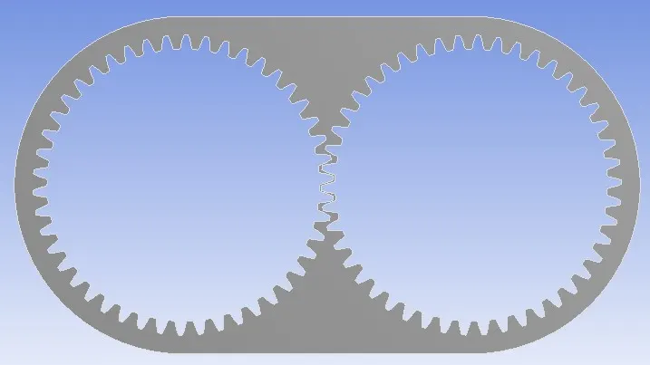
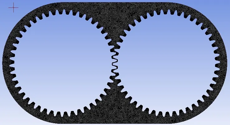 Fig: 2D surface of the Gear Box Fig:Meshed Surface
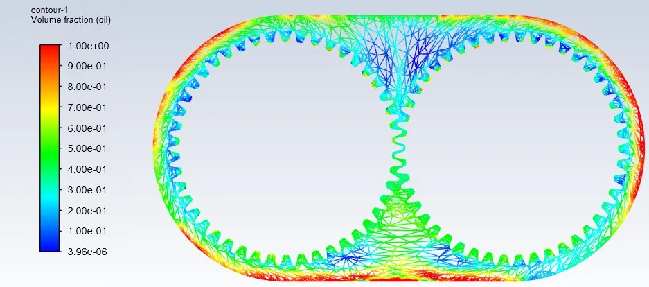
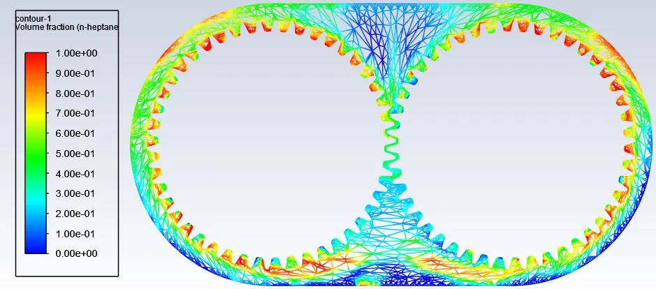
A pressure based transient simulation is used with gravity turned on.Realizable K-Epsilon turbulence model is used with multiphase set to volume of fluid.A simple scheme is used for the pressure velocity coupling with other parameters using the first order solvers.2 simulation are carried out each at 20% and 30% immersion depth with engine oil and n-heptane as the working fluids.
A UDF file is used to give the required motion to the both gears with an angular velocity of 2 rad/s.Adaptive controls is used to mark the fluid region in the gear box at 20% and 30% immersion depths.Since both the fluid and solid bodies are moving we activate the dynamic meshing for the geometry.
- Engine Oil
- 20% Immersion
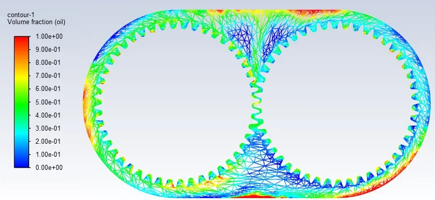 Animation: https://drive.google.com/file/d/1VaXyrLRL7RZLCowiEmGOylCC4yjaxQz6/view?usp=sharing
 - 30% Immersion
 Animation: https://drive.google.com/file/d/1h90SnsfuM7sautVC1GqDE6D2g8952_Lf/view?usp=sharing
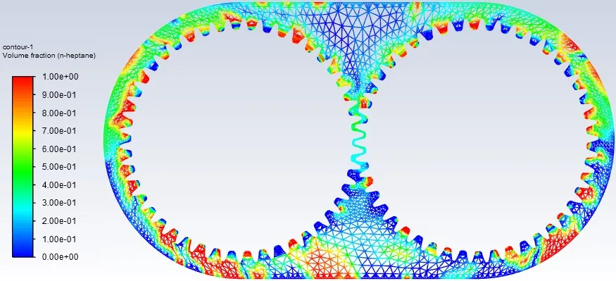
- N-heptane
- 20% Immersion
 Animation: https://drive.google.com/file/d/1gRmdfndOZAMwAWpSF5Styttbv4Ji21JQ/view?usp=sharing
 - 30% Immersion
 Animation: https://drive.google.com/file/d/1sYZFl0D8sqvFyocbMisvFZmAQ5RoOuNr/view?usp=sharing
Results
- Sloshing is more in N-heptane when compared to Engine oil for both the cases.
- For 20% immersion,less than 0.2 volume fraction of the lubricant is present between the tooth faces. Hence the gear teethes are under lubricated in both cases.
- For 30% immersion,around 0.3 volume fraction of the lubricant is present betweem the tooth faces.
- Higher volume of fluid in the gear box means better lubrication of gears.
- Sloshing effect decreases with increase in the viscosity of the fluid.