Meshing of the Suspension Assembly using ANSA
Introduction
The suspension system works with the tires. frame or unitized body, wheels, wheel bearings, brake system. and steering system. All of the components of these systems work together to provide a safe and comfortable means of transportation. The suspension system functions are as follows:
- Support the weight of the frame, body, engine, transmission, drive train, passengers, and cargo.
- Provide a smooth, comfortable ride by allowing the wheels and tires to move up and down with minimum movement of the vehicle.
- Work with the steering system to help keep the wheels in correct alignment.
- Keep the tires in firm contact with the road, even after striking bumps or holes in the road.
- Allow rapid cornering without extreme body roll (vehicle leans to one side).
- Allow the front wheels to turn from side to side for steering.
- Prevent excessive body squat (body tilts down in rear) when accelerating or with heavy loads.
- Prevent excessive body dive (body tilts down in the front) when braking.
Since the suspension assembly is an important part of the vehicle, it is necessary to have the good volume mesh for the same inorder to determine the exact point of failure (if any)during the simulation so that real life accidents can be prevented.In this project we are going to deploy the volume mesh using the 2D mesh as our outline and then deploy the rigid body connections.
Objective
To generate the volume mesh for the given suspension assembly and to deploy the necessary rigid body connections to the same.
Procedure
- Meshing
- Perform Topo and geometry cleanup.Many surfaces are very close to each other we see many triple CONS present in the geometry as ANSA tries to paste all the nearby CONS. This is removed by releasing the triple CONS and performing Topo on the very same released CONS.
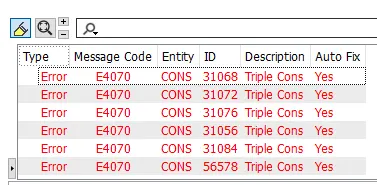
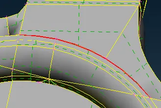
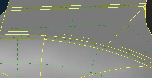 Fig : Geomery Check Fig: Releasing the Triple CONS Fig: Performing TOPO on the Released CONS
 - Assigning the mesh length and mesh quality parameters for the assembly.
- The 2D mesh is deployed onto the assembly part by part.The meshing is done using the tria elements as it forms the base for the tetra elements during the solid mesh.Tetra elements capturtes the curvature of the geometry more accurately with minimal error.
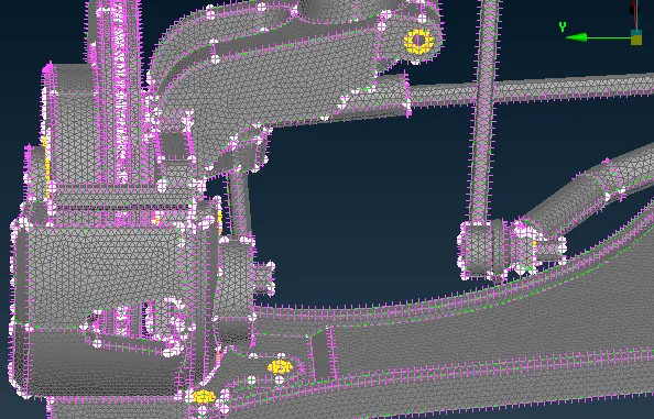
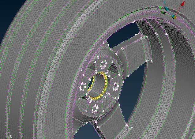 Fig: 2D mesh of Assembly Fig: 2D mesh of Rim and Tyre
 - For the parts having thickness less than 5mm, the shell mesh is deployed by extracting the mid surface for those elememts.The mid surface is extracted automatically using the casting midsurface function.After this, a separate PID is created for those surfaces with the actual thickness (3mm) of the parent geometry.
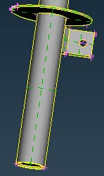
 Fig: Parts having thickness <3mm Fig: Midsurface using Casting
 - For solid meshing,initially, a new solid PIDs are created for the separate part volumes.
- The volumes are meshed with tetra elements with 0 tet collapse elements.
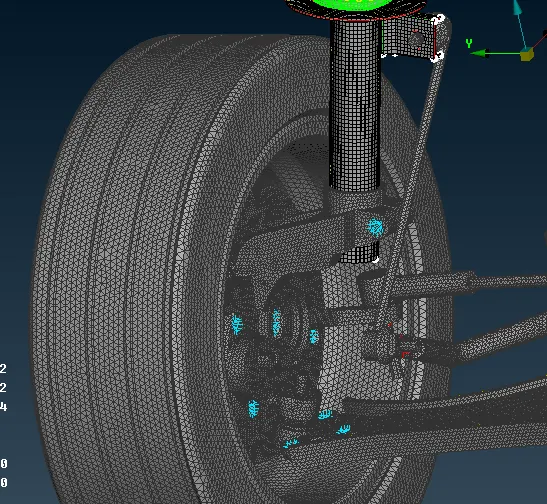 Fig: Volume mesh of Tyre Assembly
- Connections
- Cluster rigid body elements(RBE2) are deployed on all the holes in the assembly.The RBE's are deployed using the multi node RBE tool and then selecting all the node points of the holes.A master node is created at the center of the hole.
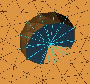 Fig: Cluster RBE2
 - If there are 2 or more holes near to each other, the parts are connected using the 2-node RBE2.A yellow color stem is deployed between the 2 master nodes of the holes which depicts a bolt connection between the two parts.
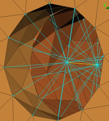 Fig: 2-Node RBE2
 - The spring is made up of CBAR elements of 4mm length.First,the middle curve of the spring is extracted using the curve middle function.This middle curve is then converted into a CBAR elements using the CBAR fucntion in the NASTRAN deck.
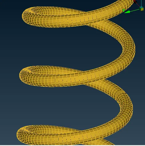 Fig: Suspension Spring made from CBAR elements
Conclusion
For a good solid mesh, we should have a good 2D/shell mesh.Choice of mesh to be deployed should be based on the overall thickness of the geometry,not all parts can be volume meshed,some of them may require a shell mesh.For the volume mesh, we should have a proper definite volume,if not, some of the parts may go unmeshed.
Similarly,cluster RBE's cannot be created everywhere.At places where there is a hole one part and a shaft/stem like projection on the other, we should make use of the 2-node RBE's to show the linkage between the two parts.Springs and other damper parts should be illustrated using the CBAR/CBEAM elements where we can define the stiffness/ damping factor of the part.Direct meshing of these parts should not be done as it beats the purpose of those parts as simualtion softweares may automatically assume it as a solid element and not as a damper.