Flow over Ahmed Body
Introduction
External car aerodynamics study has a great importance in overall efficiency of a car. The study is generally is based on simulation of air flow over a car , the resulting drag and lift forces and their effects on the car .High drag force will cause a reduction in fuel efficiency and a vehicles top speed, whilst lift can positively or negatively affect tire traction depending on whether it is in an upwards or downwards direction. Accurate measuring of the drag and lift forces computationally in turn depends on accurate modelling of turbulent flow, thus there is a need verify the accuracy of current turbulence models in an automotive context.
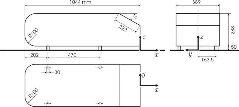
The Ahmed body was first created by the S.R. Ahmed in his research "Some Salient Features of the Time-Averaged Ground Vehicle Wake" in 1984.The shape of the Ahmed body is designed in such a way to mimic the typical flow field features of a car bluff body, namely “a strong three-dimensional displacement flow in front, relatively uniform flow in the middle and a large structured wake at the rear”, whilst being simple to model. All dimensions are fixed apart from the rear slant angle alphaα, which can be set at different angles, typically from 0 to 30 degrees to study the difference this makes to the rear wake. Ahmed found that depending on the rear slant angle used, the drag coefficient and the amount each area of the body which contributed to the drag coefficient changed.
The general dimensions of Ahmed body is
Objective
The primary aim of this project is to determine the accuracy, validity and ultimately the usefulness of the K-epsilon, and K-omega turbulence models using the Star CCM+ CFD software and comparing the results to similar results from wind tunnel experiments.
Modelling
The Ahmed Body is modelled to the exact geometry described by Ahmed (1984), using STAR CCM+’s 3D modelling tools having 25 degree and 35 degree slant at the rear These angles were chosen to be either side of the critical angle of 30o at which separated flow occurs within the wake of the slant..
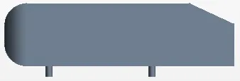
Fig: Ahmed Body with 25degree slant height
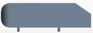
Fig: Ahmed Body with 35 degree slant height
A domain of 13m length, 4.5m width and 2m height is used.It is generally assumed that a higher cell number leads to more accurate results and we don’t have a time constraint for the completion of simulation.
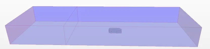
For meshing, the base size is set to 5cm so that we can have at least 15 cells along each face of the geometry. As this is an external aerodynamics simulation, we can go with trimmed cells volume mesher along with 15 prism layers.The mesh is setup with a wake refinement to allow better details of the rear flow features and precise calculation of the drag and lift coefficients.
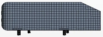
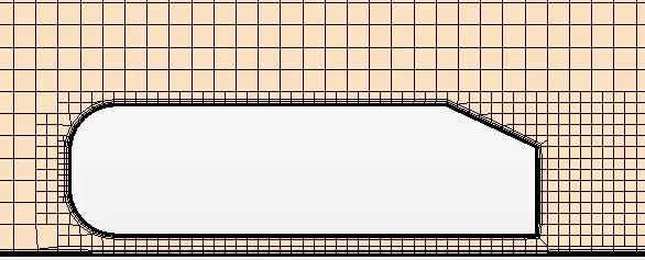
The walls and roof of the domain is set as symmetry conditions.The floor is divided into two surfaces.The initial 4m from the inlet of the floor is set to slip condition whereas the rest of the floor is set as no slip condition, to simulate the rolling road of the wind tunnel floor The leftmost wall was set as the velocity inlet with a velocity of 40m/s, and the rightmost wall the pressure outlet. The Ahmed body was set with a no slip condition. 2 simulations with different turbulence model k-𝜀 and k-𝜔 SST for each slant angled body were undertaken.
We assume the air flow to be steady and incompressible within the entire domain.In order to capture the boundary layer effects accurately, we need y+ = 1.This requires a smaller mesh size and high computational power so instead we chose the wall distance method along with the all y+ wall treatment.The initial conditions are set to 1atm pressure (absolute) and velocity of 40m/s along the flow direction so that our simulation converges easily.
In order to calculate the coefficient, Frontal area and Force Coefficient reports are created for lift and drag each.A separate report to calculate the outlet velocity is created in order to check the convergence.
Flow Parameters
Kinematic viscosity of air: 15 × 10-6 m2/s
Bulk velocity: Ub = 40 m/s
Height of body: h = 288 mm
Reynolds number based on height of body: Re = 768,000
Formulaes
Drag Coefficient:
`C_d=(2D)/(ρAV^2)`
Where D is the drag force, 𝜌 the density of the fluid, A the reference area facing the flow and V the flow velocity.
Lift Coefficient:
`C_l=(2L)/(ρAV^2)`
Where L is the lift force, 𝜌 the density of the fluid, A the reference area facing the flow and V the flow velocity.
Plots and Validation
K-Epsilon
25 Degree
35 Degree
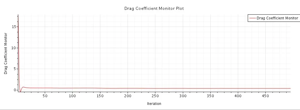
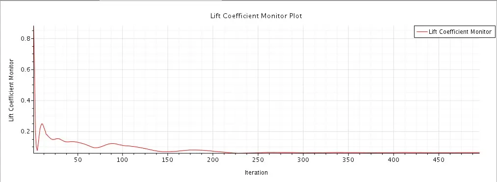
Validation
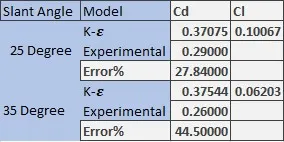
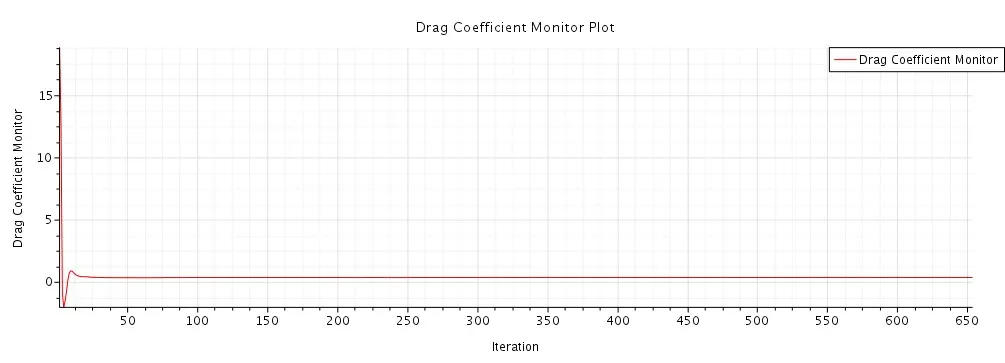
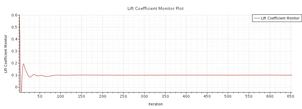
The calculated Cd values are closer to the experimental value, but there is still a disparity.With a high percentage error, it would be unacceptable for commercial application purposes.The high percentage error maybe due to the mesh size and the computational power.Since our major focus is on calculating drag coefficient,we neglect the lift coefficients.
K-Omega SST
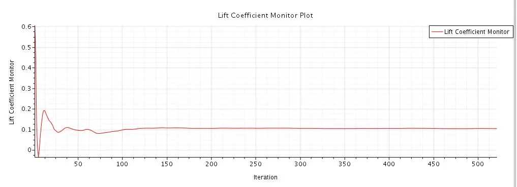
25 Degree
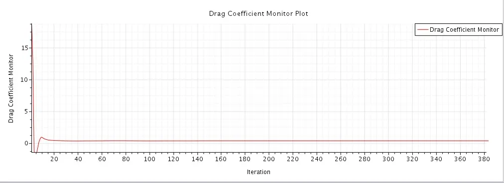
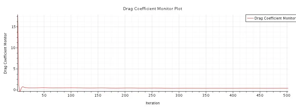
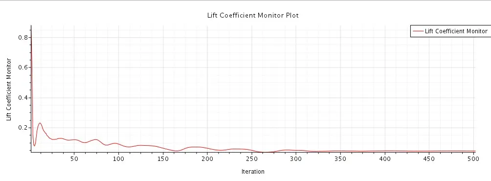
35 Degree
Validation
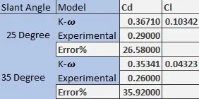
The calculated Cd values are closer to the calculated K-epsilon value when compared with the experimental model. The error percentage reduction is minor for 25 degree body but is very high for 35 degree body which justifies the use of the K-Omega SST model over K-Epsilon model.The closeness of the values between our 2 models proves that our simulations works fine.Although in order to achive the accurate results, we need more finer mesh,optimum domain size and more computational power to run our simulations.
Contours
- Pressure
- 25 Degree
K-Epsilon
K-Omega SST
35 Degree
K-Epsilon
K-Omega SST
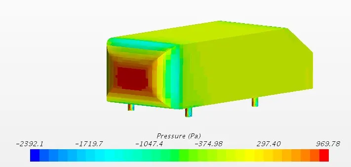
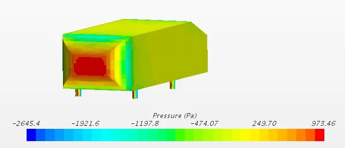
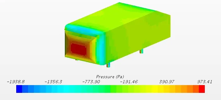
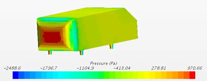
The center portion of front face experiences maximum pressure.A negative pressure region is created around the filleted portion of the front face and at the rear portion of the body due to which velocity of the around that region increases.K-omega model gives a smooth contour when compared to the K-epsilon model.
- Velocity
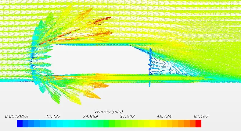
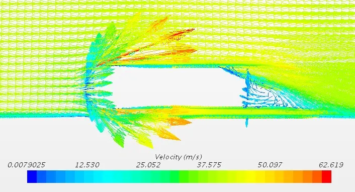
- 25 Degree
K-Epsilon
K-Omega SST
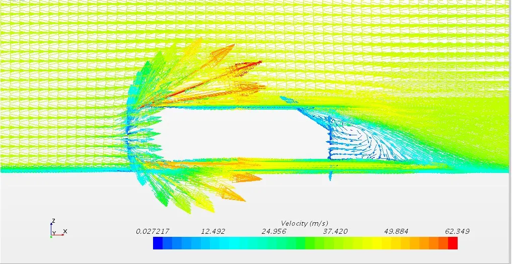
- 35 Degree
K-Epsilon
K-Omega SST
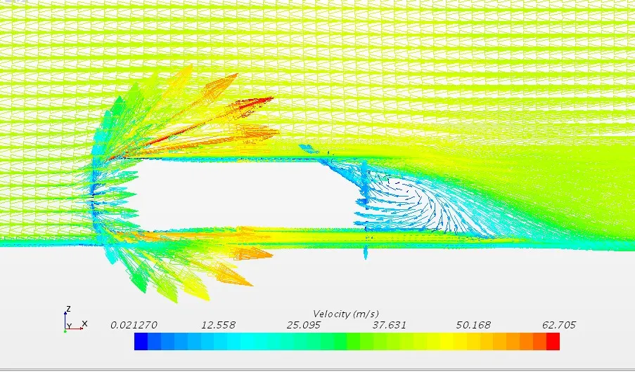
By applying Bernoulli's principle,velocity increases at the front top surface due to the filleted portion where there is low pressure.Flow recirculation happens at the rear end of the body due to flow separation.K-Omega model gives more accurate flow vortex when compared to the K-Epsilon model.Flow reattachment length increases as the slant angle increases.
Velocity Profiles
25 Degree
At the symmetry plane,the velocity profile follows a parabolic path from the slant to the rear end of the body when moving along the direction of flow.We can see some negative velocity points behind the body due to flow recirculation caused by the adverse pressure gradients (low pressure region).Flow again achieves the parabolic path when moving along the height of the body. The profile tracing is more smoother in the K- Omega SST model when compared to the K-Epsilon model because SST model uses K-omega model for the near wall region and K-Epsilon model for the far away wall region.
35 Degree
At the symmetry plane,the velocity profile follows a parabolic path from the slant to the rear end of the body when moving along the direction of flow same as the 25 degree body.Similarly,we can also see the negative velocity points behind the body.These negative velocity points seems to have shifted opposite to the direction flow which suggests that the recirculation vortex tend to shift to the left of the body as the slant angle increases.Also, the velocity seems to increase above the body because of the flow separation.
Conclusion
- At shallow rear angles,K-Omega SST model is the most accurate among the two CFD models.
- Both the models predicts almost same drag coefficients,although more accuracy can be achieved at the cost of computing power and simulation time.
- Both these models were more accurate at low slant angles and were inaccurate at steeper slant angles meaning the drag force produces more complex equations which should be treated more carefully no matter what turbulence models we use.