Week 4
Aim
For the given component, check for the geometrical errors and mesh with the given element Quality criteria.
Procedure
- Perform Topo and then check for any geometrical errors.
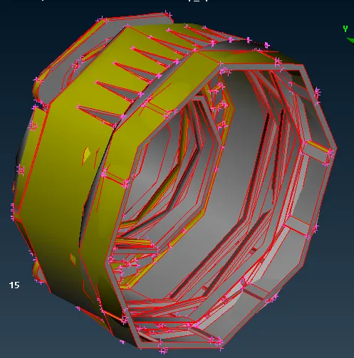
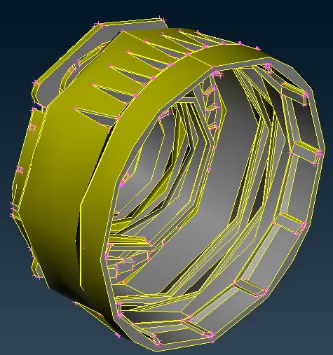 Fig: Without Topo Fig: With Topo
 - For both the inner and outer rings we offset the inside surfaces to extract the mid surfaces because both the rings have varying thickness on their inside and outside surfaces and since there are other entities (threads/ribs) attached to the inner surfaces, using the inner surface for the offset is always a good option.
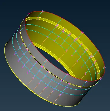
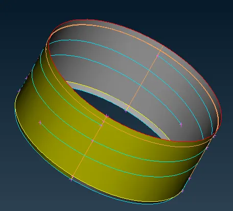 Fig: Outer Ring Midsurface Fig: Inner Ring Midsurface
 - For, the top outer and inner ribs we use the middle feature to extract the middle surface as both the faces of those ribs are clearly visible and other entities are attached to it.
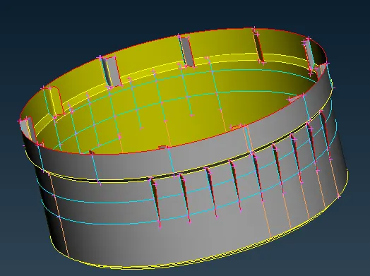 Fig:Middle Surface of the Outer Ring along with the ribs
 - The middle surface of threads are extracted by using the middle curve lines because the threads have 2 different types of the faces, curved faces at the front having non-uniform thickness and rectangular flat face at the back.
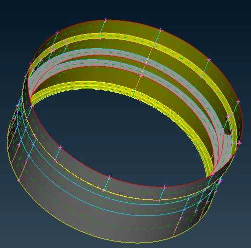
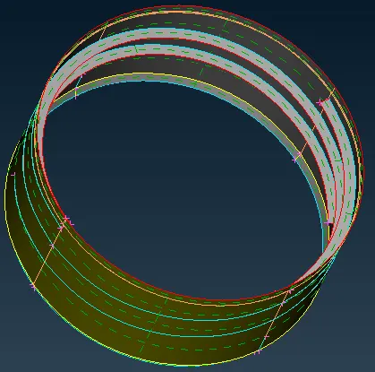 Fig: Midsurface of Outer Ring with Thread Fig:Midsurface of Inner Ring with Thread
 - For the teeths in the middle, the middle surface is extracted by using the curve middle and then rotating that middle surface along the circular base.
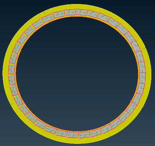 Fig: Midsurface of Teeths
 - The base mid surface of the geometry can extracted by manually offsetting the inner faces as there are many entities connected to each other.So auto mid surface may cause the faces to overlap each other thereby requiring more cleanup commands.
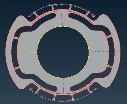 Fig: Bottle Cap Base Midsurface
 - Simultaneously,separate PID's are also created for these mid surface. Once all the mid surface extraction is complete we can check whether the surface extracted are aligned, connected to each or not in the PID mode and which surface requires addtional operations.
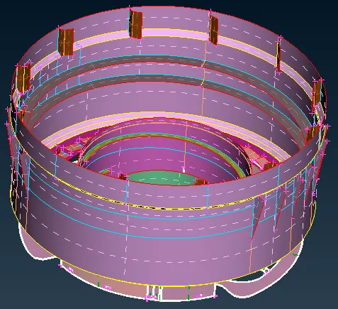 Fig: Bottle Cap Mid-Surface in PID Mode
 - Meshing of these surfaces should be done one by one having atleast 1st level neighboring elements visible, so that proper mesh flow is attained.
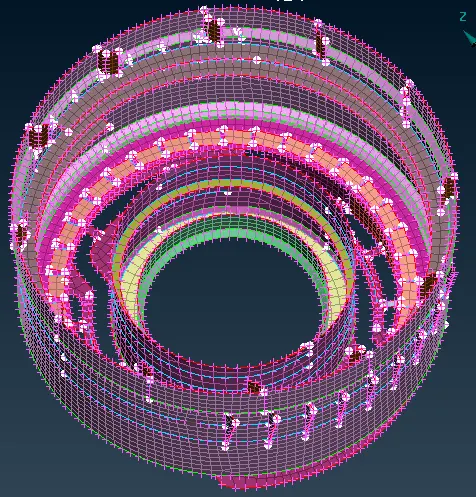 Fig: Meshed Mid-Surface
 - After meshing we now add thickness to the various PID created to convert the shell mesh into solid and check whether the thickness assiigned is correct or not.
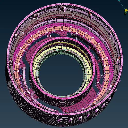
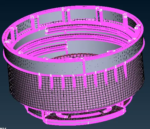 Fig: MidSurface Solid Mesh Fig: MidSurface Solid Mesh with Parent Geometry
Learning Outcomes
- Auto Mid Surface extraction.
- Meshing of the surfaces wherein mutilple entities are joined together.
- Middle Surface extraction of curved faces.
- Use of transform rotation
Conclusion
- Auto mid Surface extaction cannot be used everywhere.
- Meshing should be done by having atleast 1st level neighboring elements visible to achieve proper mesh flow.