Gate Valve Parametric Study
1. The aim, Introduction, Theory:
The main objective of this challange is to perform the numerical simulation of Gate Valve(Sluice Valve) for different percentage of gate opening in order to determine the mass flow rate and plot the coefficient of flow and flow factor.
A gate valve is a mechanical device generally used to control the flow rate of fluid through the pipe. A gate valve is operated by means of hand wheel which will controls the opening and closing of gate disc.
A gate valve is generally used to completely shut off fluid flow or, in the fully open position, provide full flow in a pipeline. Thus it is used either in the fully closed or fully open positions. A gate valve consists of a valve body, seat and disc, a spindle, gland, and a wheel for operating the valve. The seat and the gate together perform the function of shutting off the flow of fluid.
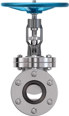
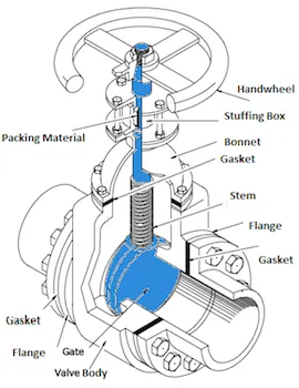
Figure 1. (a) Gate Valve (b) Sectional View of Gate Valve
2. Solving & Modelling approach:
Initially the 3-D geometry of Gate valve is opened in space claim, then by using move command in design tab give the required lift to the gate disc and click on parameter (P) in order to parameterize the gate disc lift. Extract the required fluid volume out of the gate valve geometry by using volume extract command in prepare tab.
The inlet pressure of fluid (Liquid Water) is kept constant at 10 pascal.
The following percentage of gate dic opening is used in this cahallange
10%=10mm (DP-0)
20%=20mm (DP-1)
30%=30mm (DP-2)
40%=40mm (DP-3)
60%=60mm (DP-5)
70%=70mm (DP-6)
80%=80mm (DP-7)
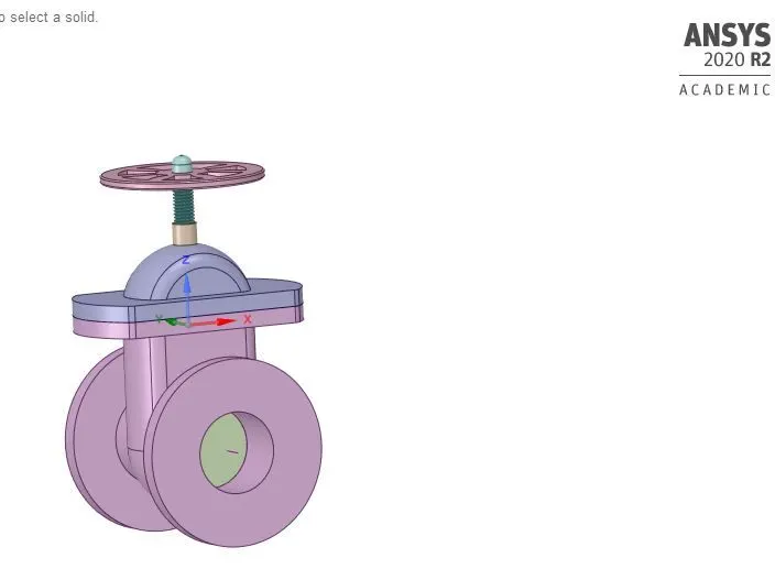
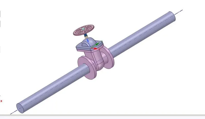
(a) 3-D geometry of Gate Valve (b) Extracted volume
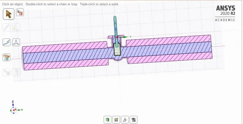
(c) Sectional view afte volume update
Figure 2.
3. Pre-processing and solver setting:
Meshing:
The following set up is used for meshing
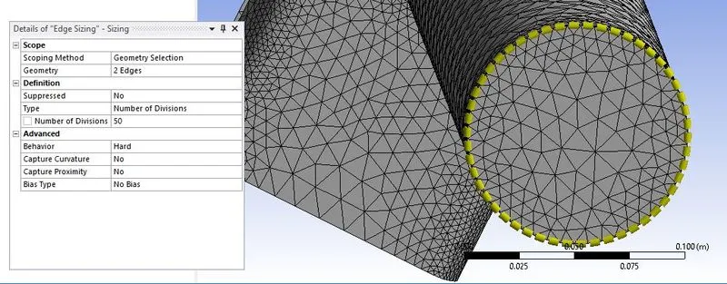
Figure 3. Edge Sizing
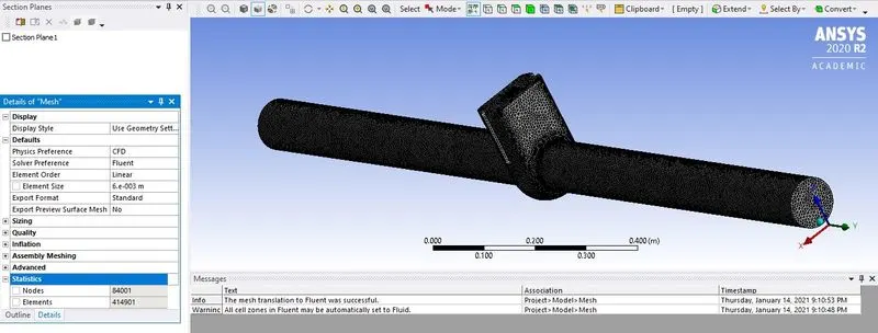
Figure 4. Mesh Element size set up.
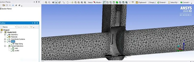
Figure 5. Sectional View of Mesh.
Solver Setting:
The following set up is used for solving the gate valve challange.
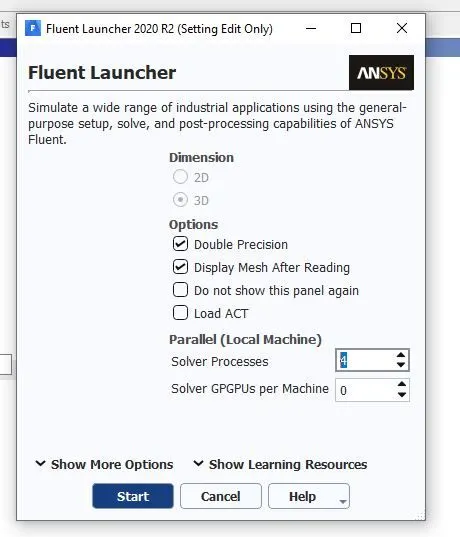
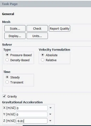
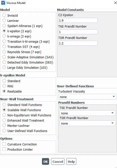
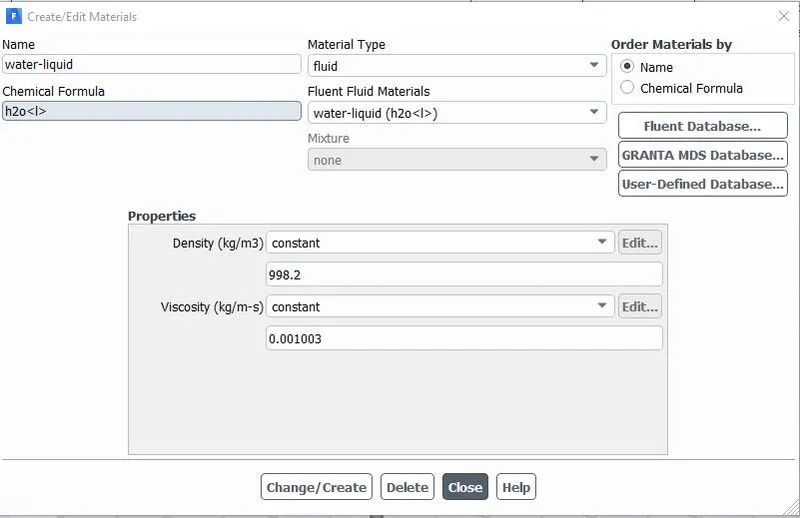
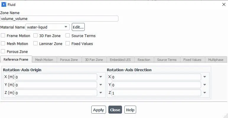
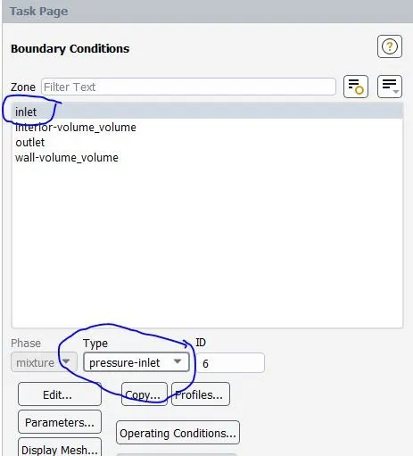
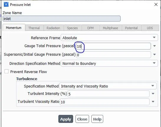
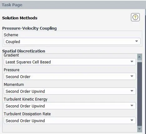
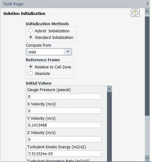
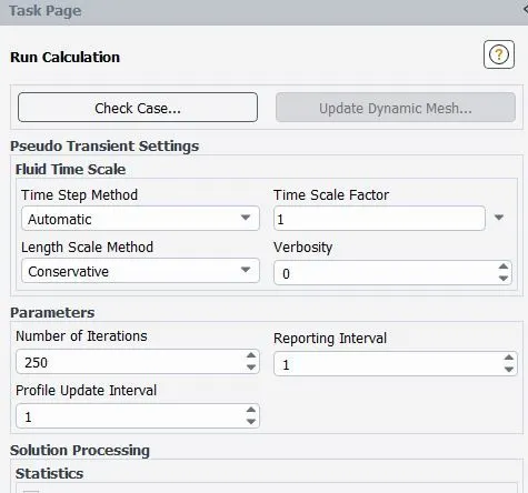
Figure 6. Solver Settings
4. Results:
Initially the calculation are run for the 10mm opening of gate disc with 200 number of iterations and then under parameter tab all the design points selected for this stusdy are updated.
i) DP-0 10% opening of gate disc (10mm):
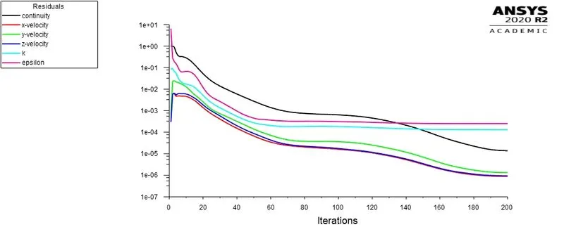
Figure 7. Residual Plots for DP-0 (10%)
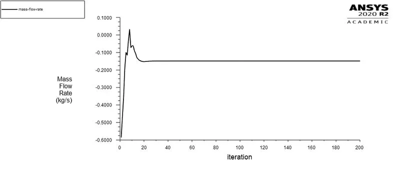
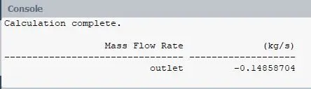
Figure 8. Mass flow rate plot for DP-0.
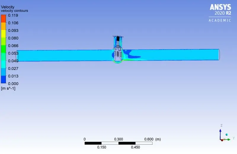
Figure9. Velocity contours for DP-0.
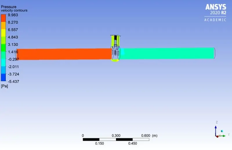
Figure 10. Pressure contours for DP-0.
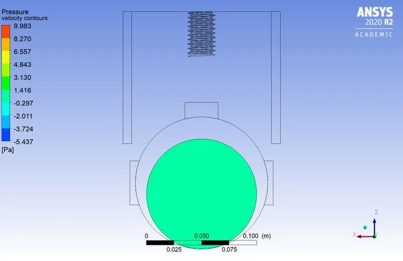
Figure 11. Pressure at outlet.
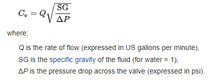
Coefficient of Flow: It is the coefficient which defines the efficiency of fluid flow through the gate valve opening. It relates the pressure drop across the gate valve and flow rate.
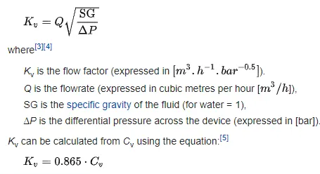
Flow Factor: The metric equivalent of flow coefficient is flow factor while the earlier one is used only in united state.
Case1: DP-0 (10% Lift)
From the obtained results the mass flow rate is
m= 0.14858704 Kg/s
Flow rate is given by
Q= m/1000= 0.14858704/1000= 0.00014858704 m^3/s
Q= 0.00014858704/0.016= 0.009 m^3/min (Because 1m^3/min = 0.016 m^3/s)
And 1 m^3/min = 264.172 gallons/min
Therefore 0.009*264.172 = 2.377 gallons/min
For DP-0 (10% lift) the pressure drop across the valve is
Pressure drop= Pressure at left side of the valve- pressure drop at right side of the valve
P= 10 pascal-1.41 Pascal
P= 8.59 pascals (1 pascal = 0.000145038 psi)
P=8.59 * 0.000145038= 0.00124 psi
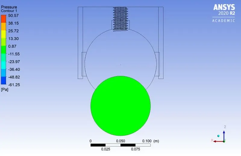
Since pressure drop at outlet is very small hence we can take the difference in pressure as 10 pascal for all the openings
Hence by using the formula for coefficient of flow we get
Cv =67.50
Flow factor is
Kv= 0.865*67.50= 58.38
After completing the clculation aprt for the first design point double click on parameter tab, design point table appears now in each row of the table define the remaining design point for remaining percentage of gate valve opening. Enter each design point with corresponding lift and update all the design point.
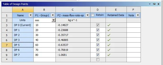
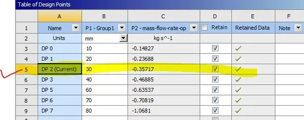
To get the solution of each design point select the design point from the table right click go to set as current design point and click as show in the table below.
ii) Case-2: DP-1 (20% Lift):
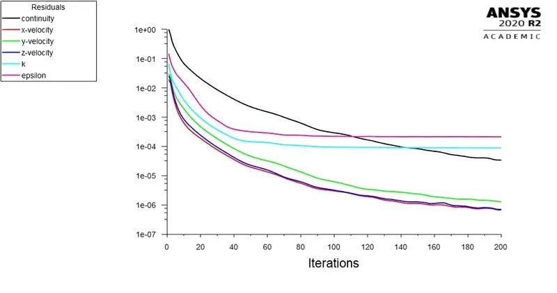
Residual Plots
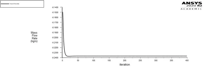
Mass flow rate plot
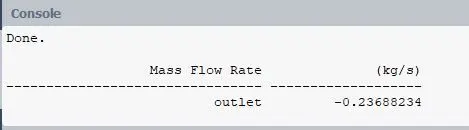
Mass flow rate
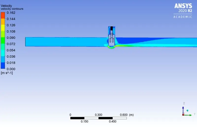
Velocity Contours
Pressure Contours
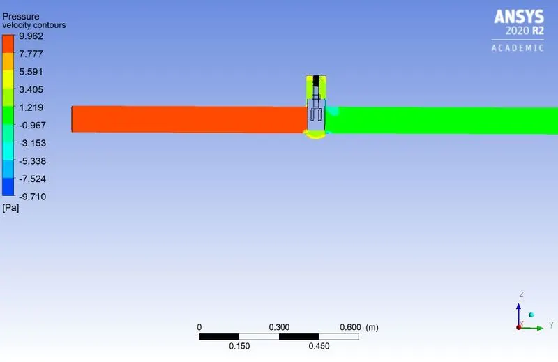
Pressure at Outlet
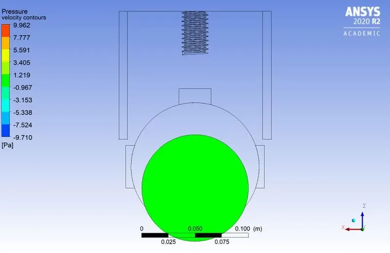
iii) Case-3 DP-2 (30% Lift):
Residual Plot
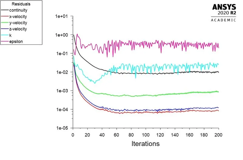
Mass flow rate plot
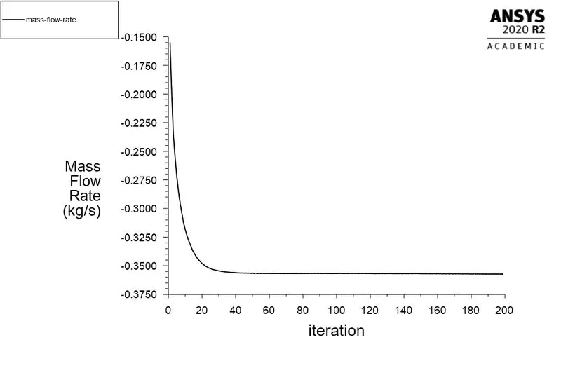
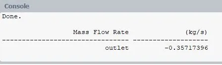
Mass flow rate
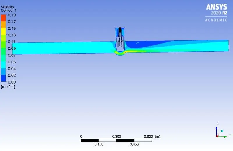
Velocity Contours
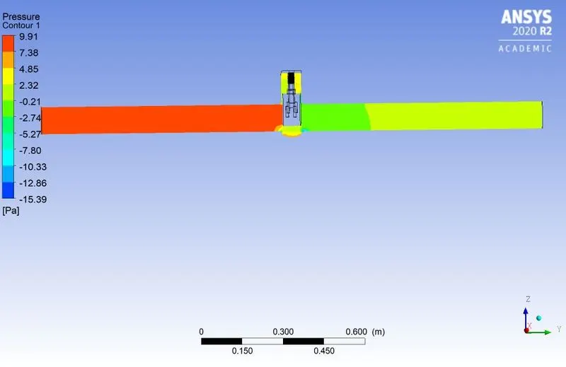
Pressure Contours
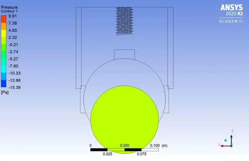
Pressure at Outlet
iv) Case-4 DP-3 (40% Lift):
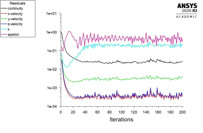
Residual Plot
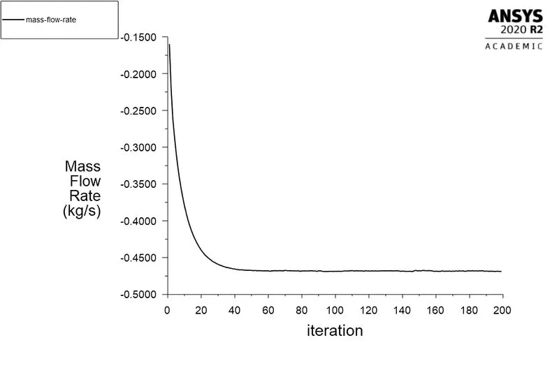
Mass flow rate plot
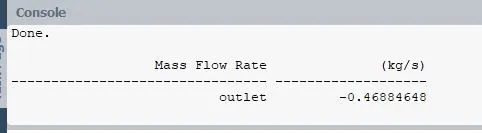
Mass flow rate
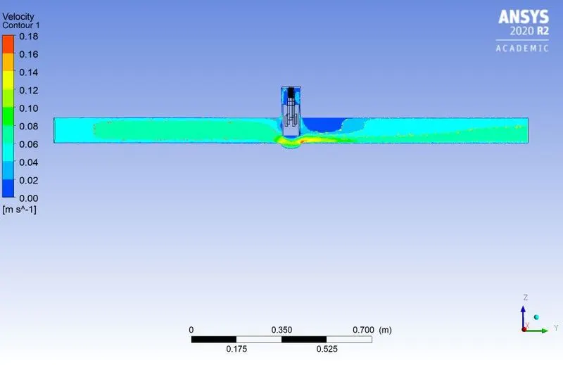
Velocity contours
Pressure Contours
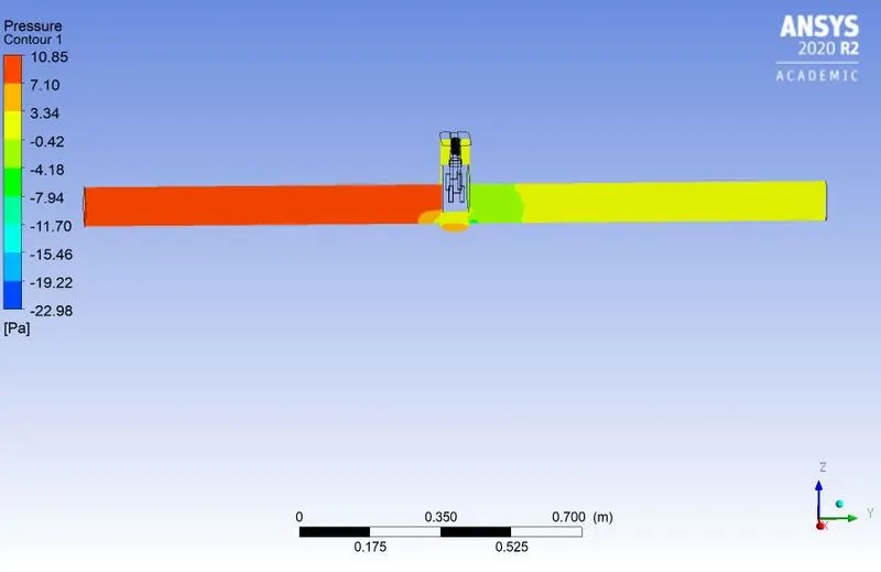
Pressure at outlet
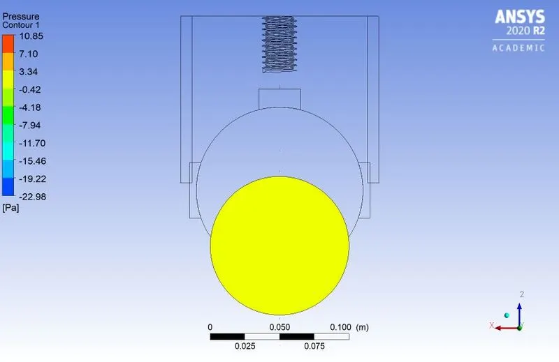
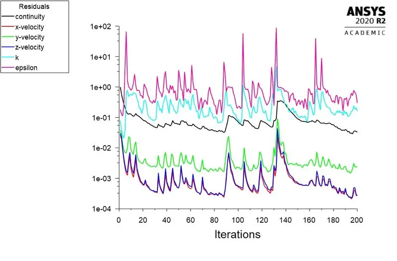
V) Case 5 DP-5 (60% Lift):
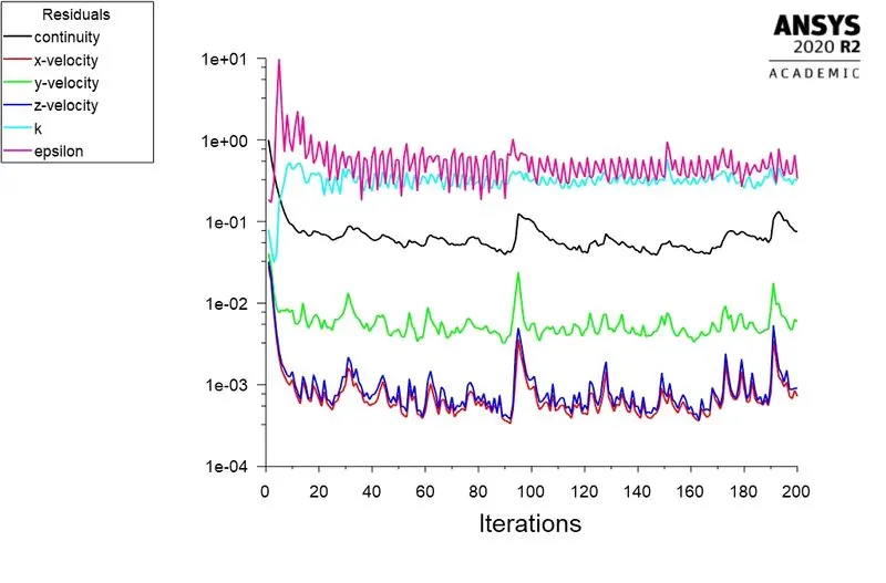
Residual Plot
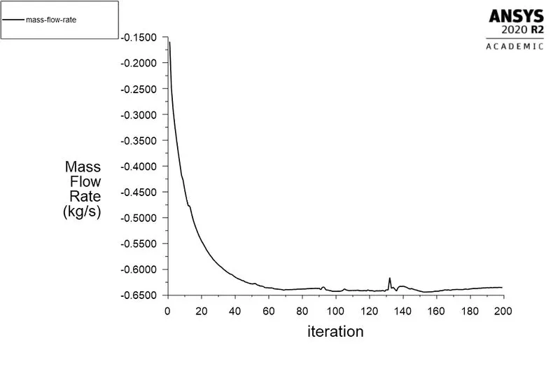
Mass Flow Rate plot
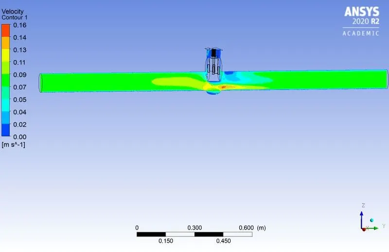
Velocity contours
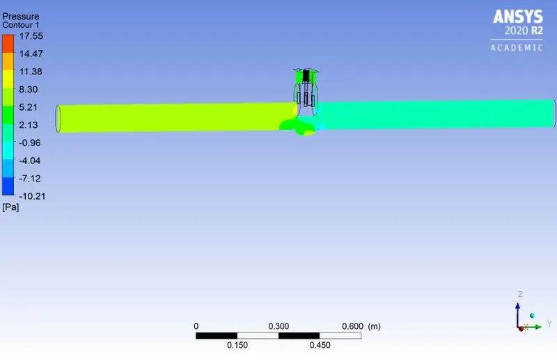
Pressure Contours
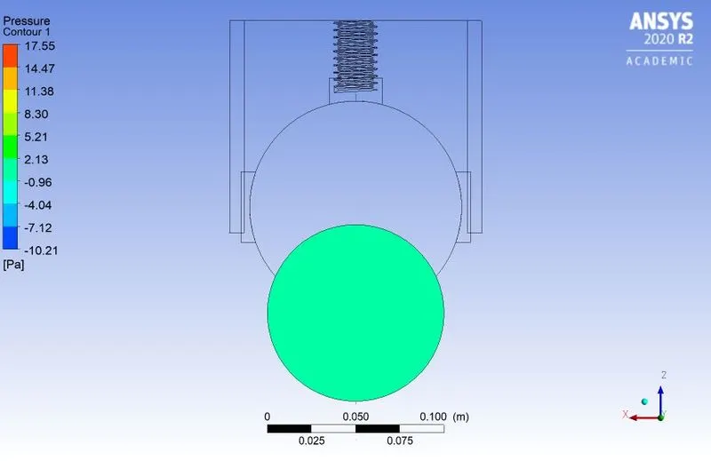
Pressure at Outlet
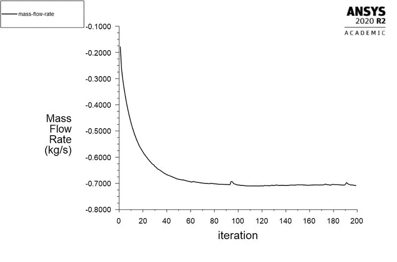
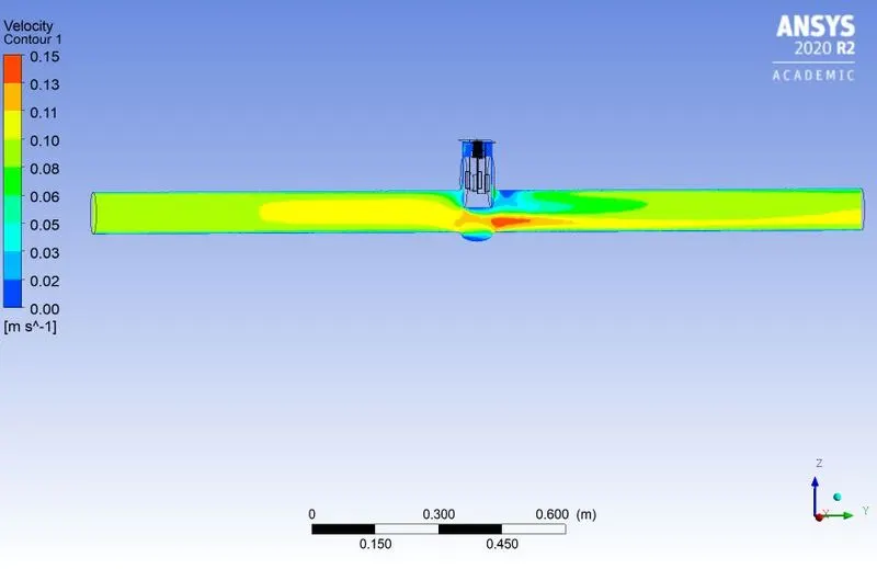
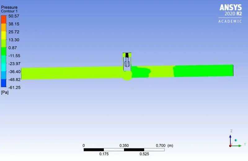
vi) Case-6 DP-6 (70% Lift)
Residual Plot
Mass flow rate plot
Velocity Contours
Pressure contours
pressure at outlet
vii) Case-7 DP-7 (80% Lift)
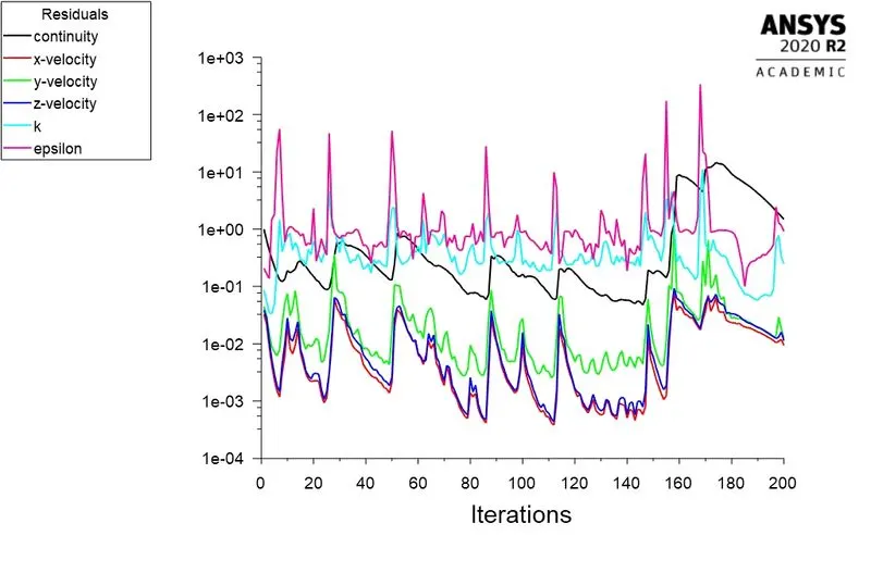
Residual Plot
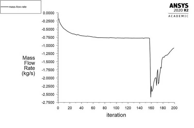
Mass flow rate plot
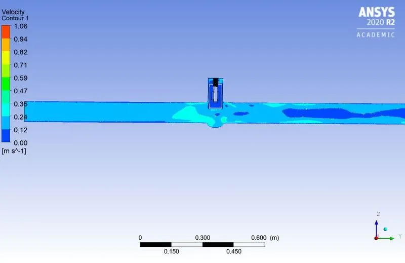
Velocity Contours
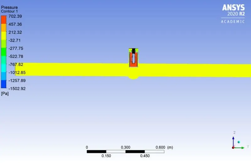
Pressure contours
Pressure at outlet
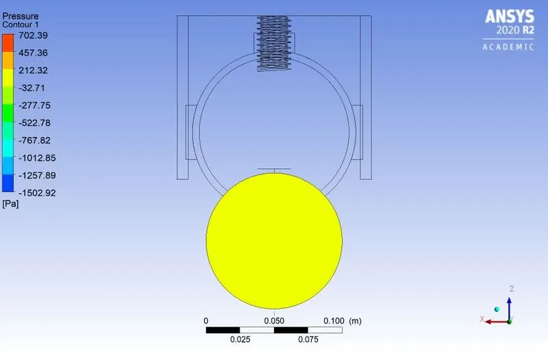
Table: Flow Parameters:
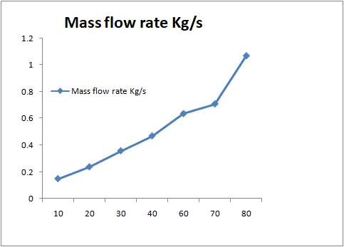
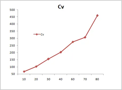
| Case No | % gate disc lift | Design Point | Mass Flow Rate (Kg/s) | Pressure drop (psi) | Flow Coefficient (Cv) US Unit | Flow Factor (Kv= 0.865Cv)Metric |
| Case1 | 10%(10mm) | DP-0 | 0.14826527 | 0.00145 | 67 | 58 |
| Case2 | 20% (20mm) | DP-1 | 0.23688234 | 0.00145 | 102 | 88 |
| Case3 | 30% (30mm) | DP-2 | 0.35717396 | 0.00145 | 154 | 134 |
| Case4 | 40% (40mm) | DP-3 | 0.46884648 | 0.00145 | 202 | 175 |
| Case5 | 60% (60mm) | DP-5 | 0.63536974 | 0.00145 | 275 | 238 |
| Case6 | 70% (70mm) | DP-6 | 0.70818695 | 0.00145 | 307 | 265 |
| Case7 | 80% (80mm) | DP-7 | 1.0681259 | 0.00145 | 459 | 397 |
(a) Line Graph of % of Gate valve Opening V/s Mass Flow rate:
(b) Coefficient of Flow V/s % of Gate valve opening:
5. Conclusion:
From the above obtianed Results the following conclusions are drawn
- With increase in the gate disc lift the mass flow rate also increses.
- With increase in the gate disc opening the coefficient of flow also increases.
- Pressure drop decreases with increase in the gate disc lift.
- The flow velocity of fluid gets affected by the percentage of gate disc opening.
- The fluid flow efficiency achieved is higher for maximum opening of the gate valve.