Gate Valve Parametric Study
AIM: To perform a CFD analysis of a fluid flowing through a gate valve.
INTRODUCTION: In this analysis, I have conducted a parametric study on the height of the gate. Initially, I have opened/lifted it to 10mm. In the next steps, the opening of the gate is set from 10% to 80%. With this opening height, I have found the mass flow rate, flow characteristics, and flow co-efficient.
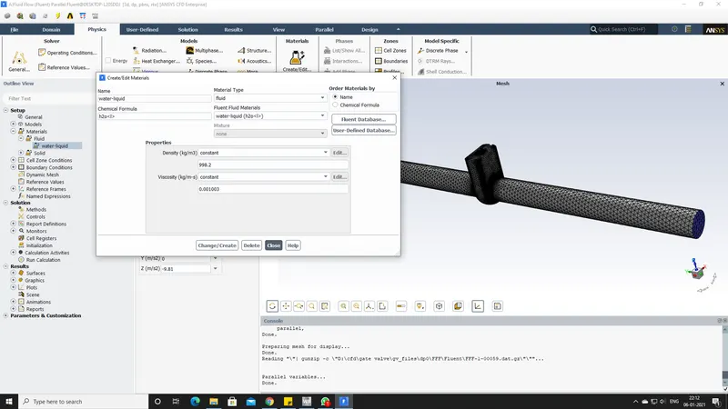
THEORY: In this analysis, I choose the standard K-Epsilon turbulence model as a viscous model and water as the fluid material.
GEOMETRY SETTINGS:
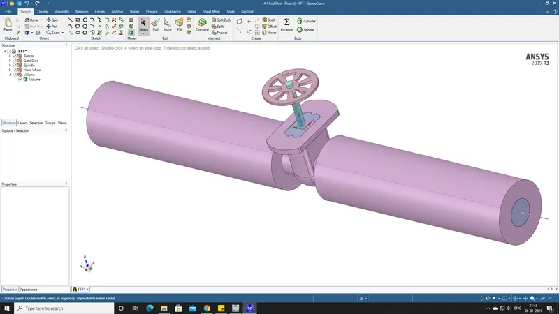
- Extract the volume from the model and pull the side pipe connections to 800 mm as shown in the picture.
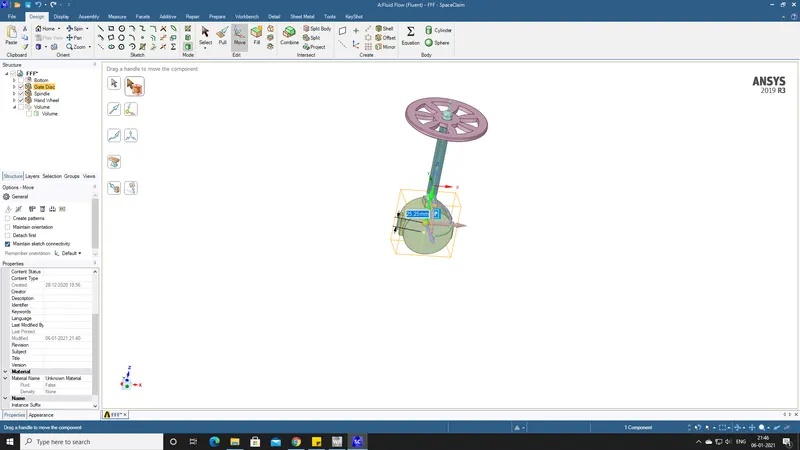
- Now, lift the gate vale to 10 mm as shown by disabling other parts.
- Insert the desired value and press the "P" to parameterize it.
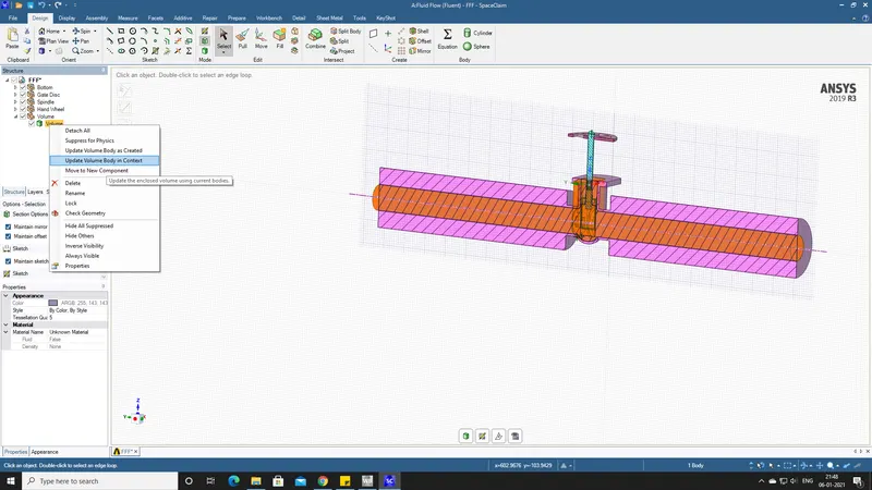
- After, entering the value update the context as shown below.
MESH SETTINGS:
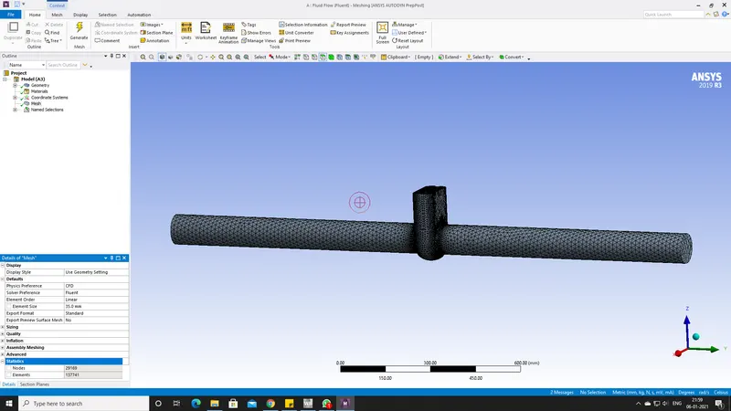
- The default meshing in my case was too large, so I have decreased the value to 35mm and the result is as shown below.
- Next, name the inlet and outlet.
FLUENT SETTING:
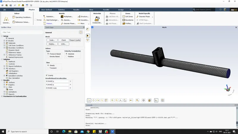
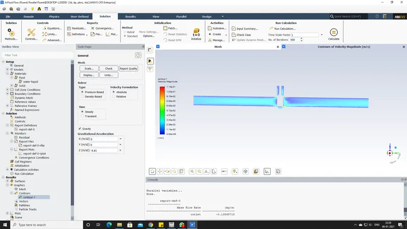
- General information, enable the gravity, pressure based, and steady state solution.
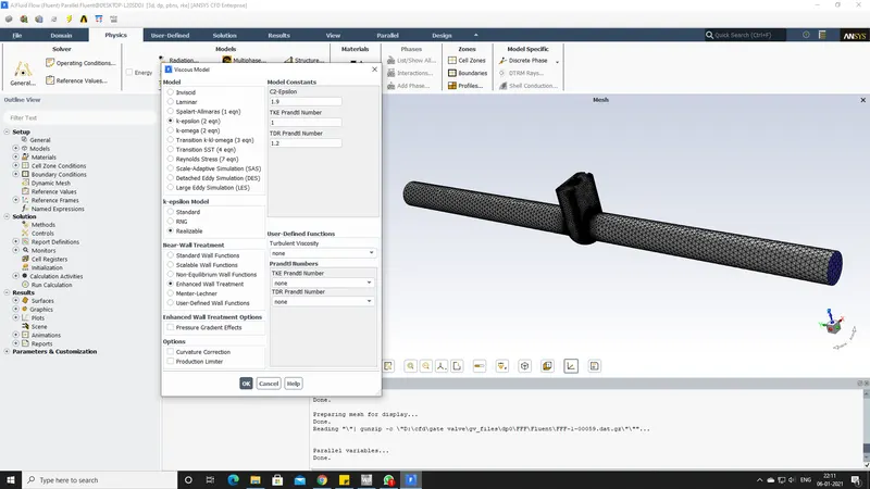
- The viscous model is set to k-epsilon, realizable.
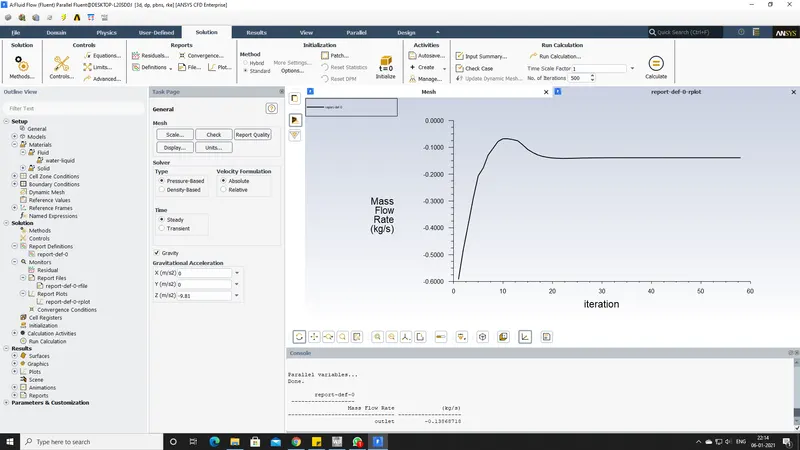
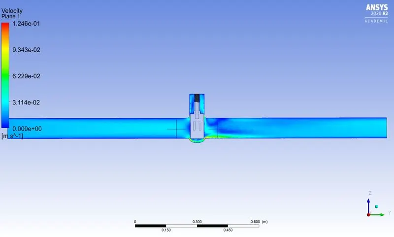
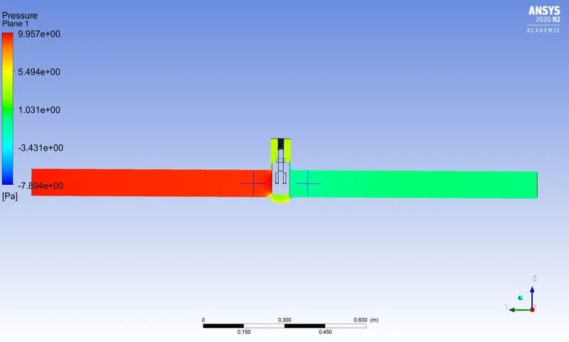
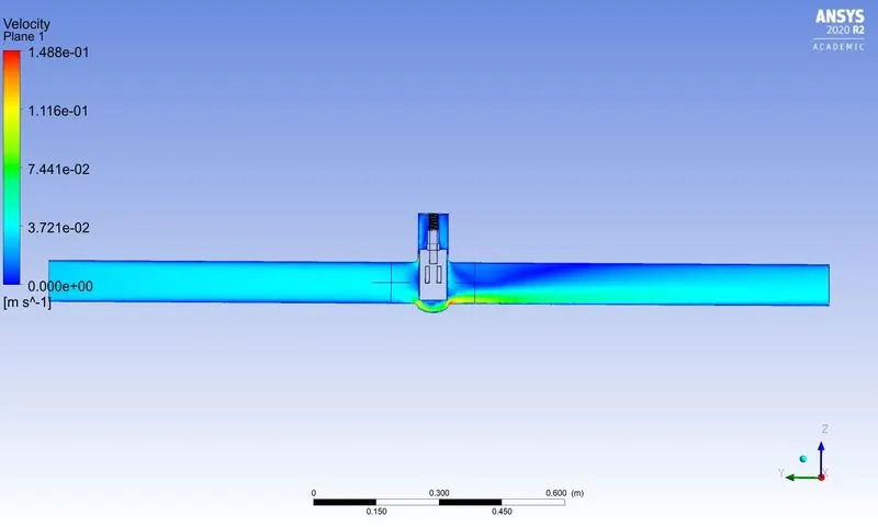
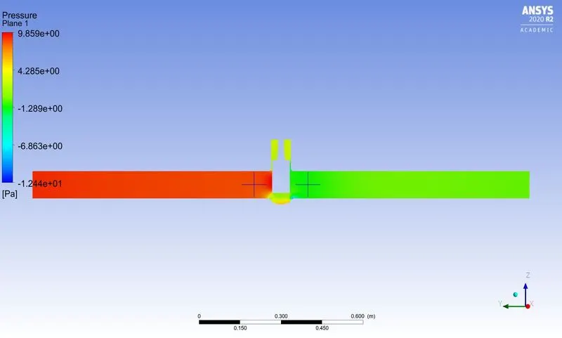
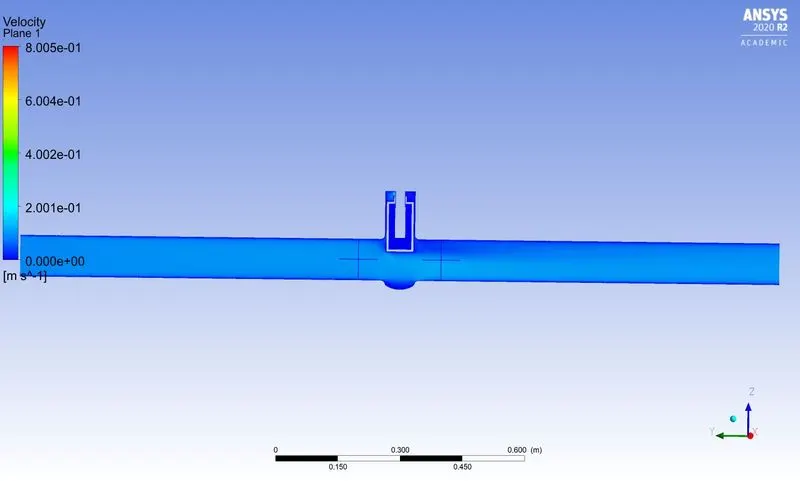
- Report the mass flow rate at the outlet, create a plane along zy and print the velocity contours.
POST-PROCESSING:
- While printing the mass flow rate report there is an option at the bottom of the dialogue box "Create output parameter" enable it to print the values in the parametric model.
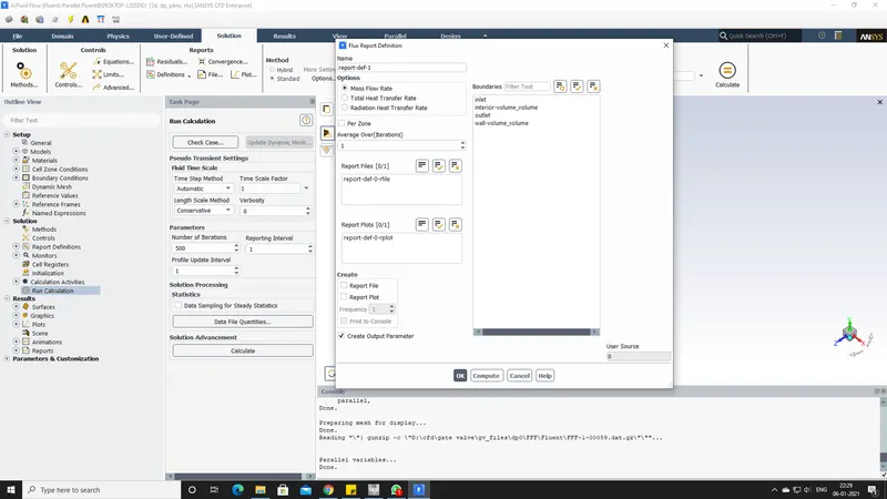
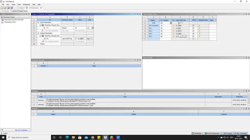
- After making the above mentioned setting we get this dialogue box and here we can get the mass flow rate of different gate openings.
PRESSURE AND VELOCITY CONTOURS:
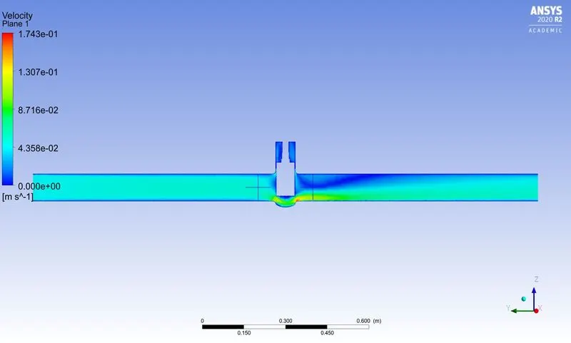
LIFT=10MM
LIFT=20MM
LIFT=30MM
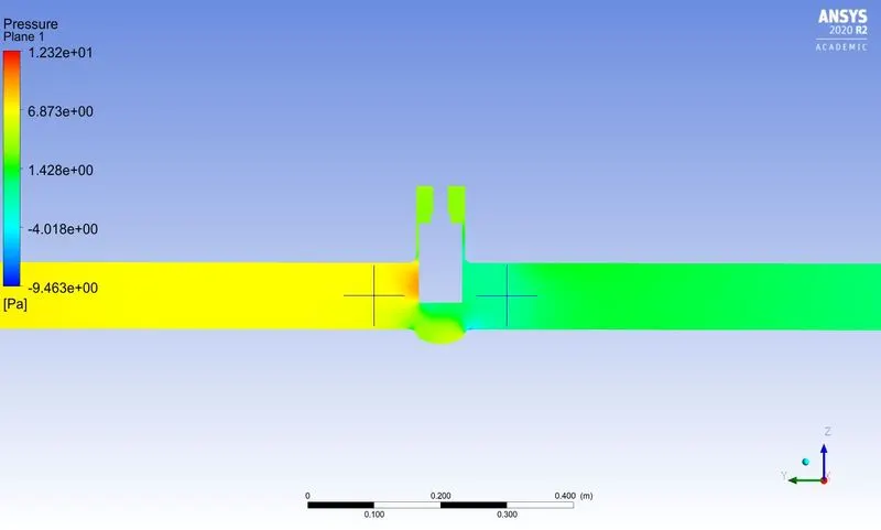
LIFT=50MM
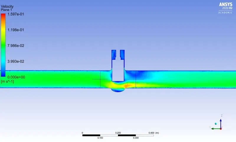
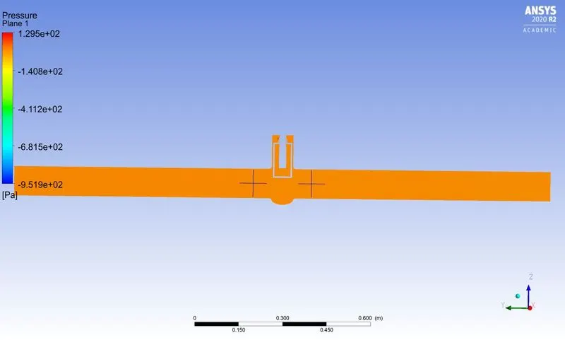
LIFT=80MM
Flow Co-Efficient and Flow Factor:
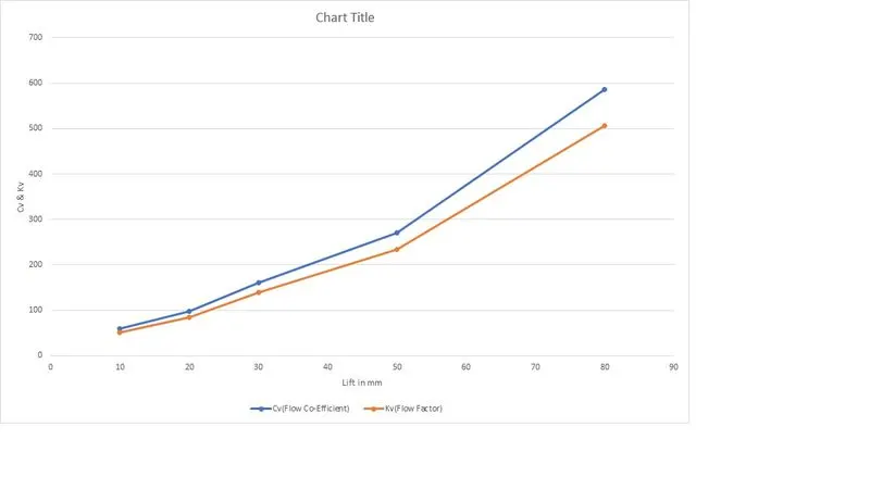
| Lift | P1 | P2 | `triangleP`PSI | Mass Flow Rate Q | Q gpm | Cv(Flow Co-Efficient) | Kv(Flow Factor) |
| 10 | 9.64 | 0.152 | 0.001376121 | 0.13868718 | 2.198191803 | 59.25668401 | 51.25703167 |
| 20 | 9.31 | 0.592 | 0.001264441 | 0.22079812 | 3.499650202 | 98.41817426 | 85.13172073 |
| 30 | 8.507 | 1.11 | 0.001072846 | 0.33071898 | 5.241895833 | 160.0367325 | 138.4317736 |
| 50 | 6.621 | 0.242 | 0.000925197 | 0.51981644 | 8.239090574 | 270.8707279 | 234.3031797 |
| 80 | 3.841 | 1.352 | 0.000361 | 0.70180851 | 11.12366488 | 585.4563854 | 506.4197734 |
- Cv is expressed in gpm/lb/in units which is known as Imperial units.
- Kv is expressed in
 units.
- The pressure difference is found by subtracting inlet and outlet pressures.
- In Fluent the pressure value units are expressed in pascals, Later I have converted them into PSI.
`K_v=Qsqrt((SG)/(triangleP))`
`K_v` is the flow factor `(m^3)/h/pa`
Q is the flow rate `m^3/h`
SG is the specific gravity of the fluid usually for water it is 1
`triangleP` is the pressure difference expressed in pascals
- Note: the pressure difference is calculated by subtracting the inlet and outlet pressure.
CONCLUSION:
- I would like to conclude, from the above observation the velocity in the first case is very low. As the opening or lift of the gate disc increases, the velocity of the flow increases.
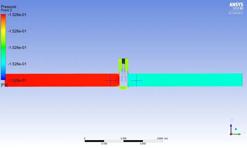
- It is evident from the pressure contours that the inlet pressure is high. As flow passes through the valve opening it decreases.
- There is a gradual increase in Mass Flow Rate, FLow coefficient, and Flow factor as the lift of the gate disc increases.
- When the valve is fully open, Mass Flow Rate, Flow co-efficient, and Flow Factor become maximum.
- Thus this study helps to analyze the different positions of valve opening and gives the benefit to get easy and quick results.