Foundation Design using SAFE
FOUNDATION DESIGN USING SAFE
- Model the isolated footing provided in week 11 challenge on SAFE. Analyze and design it to verify the size, depth and steel provided as per calculations.
AIM:
Model the isolated footing provided in week 11 challenge on SAFE. Analyze and design it to verify the size, depth and steel provided as per calculations.
INTRODUCTION: - CSI SAFE (Slab Analysis by the Finite Element Method) is the best tool for designing concrete slabs and foundations.
- SAFE provide easiness to engineer towards the safe design of structures with powerful tools like draw, analyze, design and detailing etc.
- Slab modeling, analysis, and design procedures feature a suite of sophisticated tools and applications, couple with post-tensioning, punching-shear, and beam detailing, and integrate the influence of soils, ramps, columns, braces, walls (rectilinear or curvilinear), and other interfacial elements.
- Interoperability with SAP2000 and ETABS allows users to import models, loading, and displacement fields into SAFE for more advanced local assessment of slab systems within larger structures.
PROCEDURE:
-
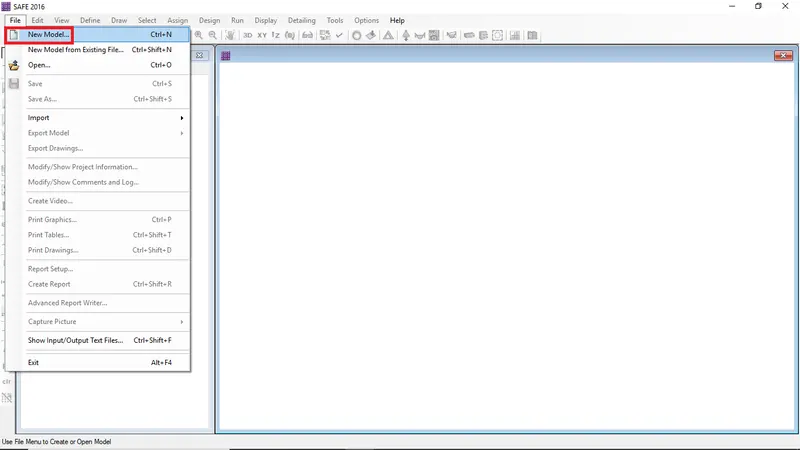
Open the SAFE software and go to file menu and click on select New Model to create new file
-
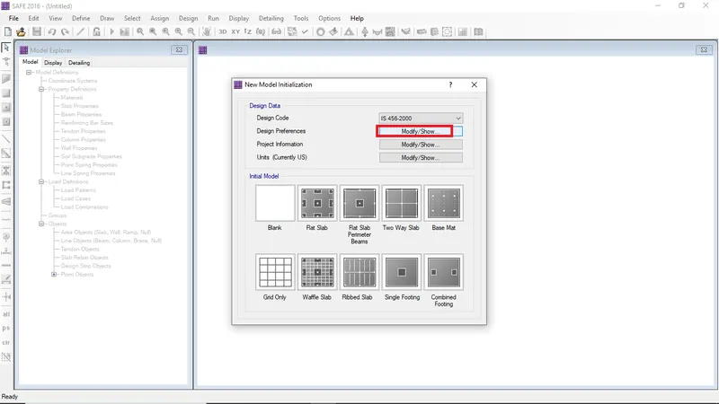
In the model initialization select design code IS 456-2000
-
Select units was selected as Metric
-
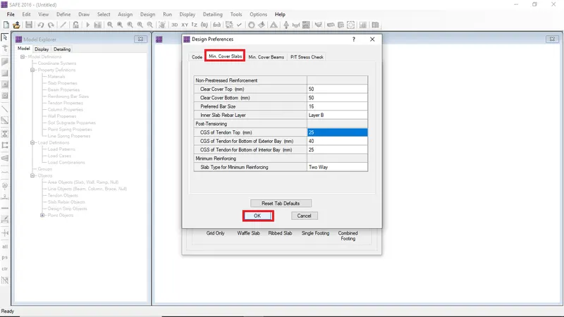
In the design preference update the cover details and bar size
-
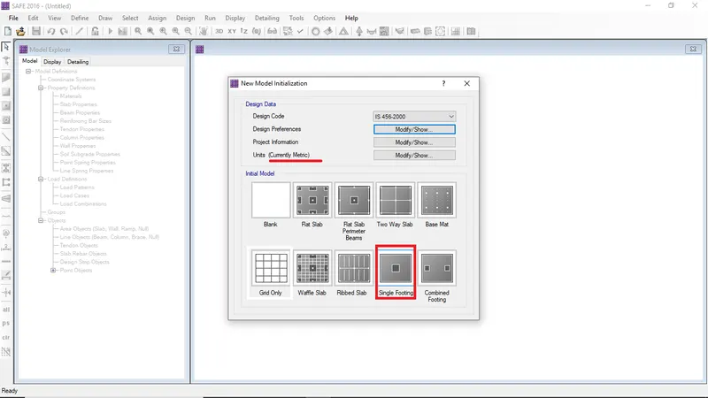
After that click on single footing to create isolated footing using template
-
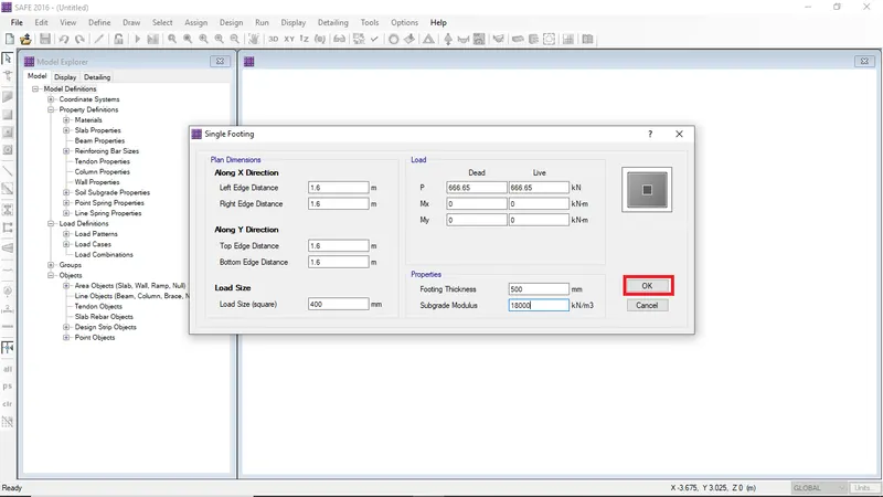
Then enter the given data of footing and load then click ok
-
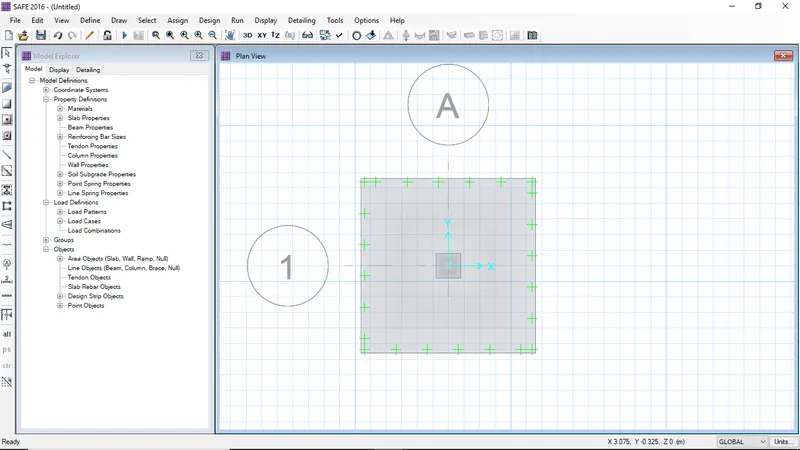
This is the SAFE software interface after entering data
-
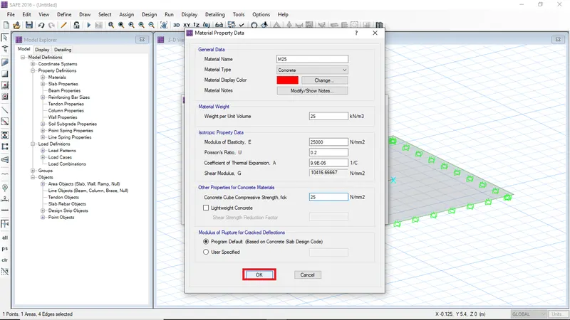
Firstly need to define the materials
-
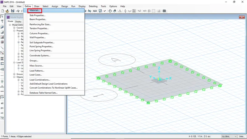
To define material properties go to define and click on materials
-
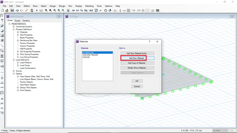
Click on add new materials to add materilas to the existind materials
-
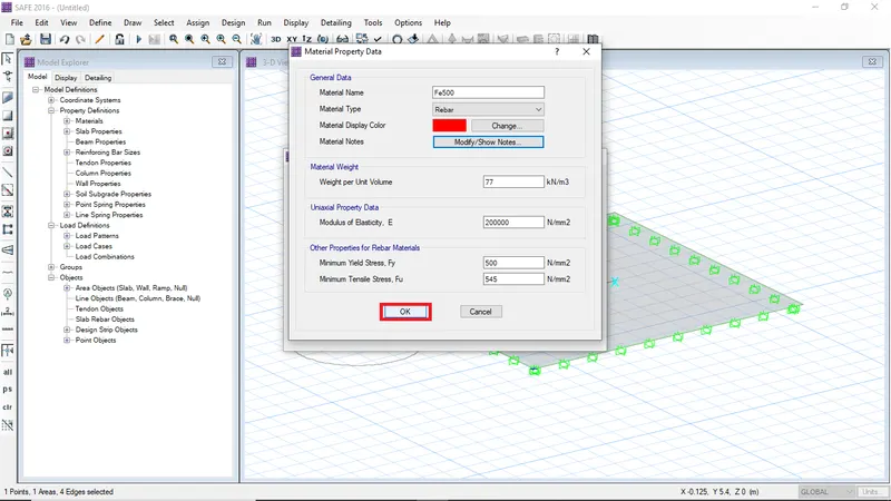
Enter material name and data and click ok
-
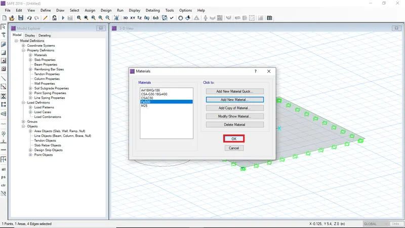
After finishing all material creation click oj to finish
-
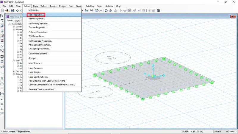
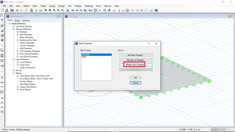
Then define slab properties
-
The software itself assigned slab peoperty but need to change material property
-
Click on modify to edit material
-
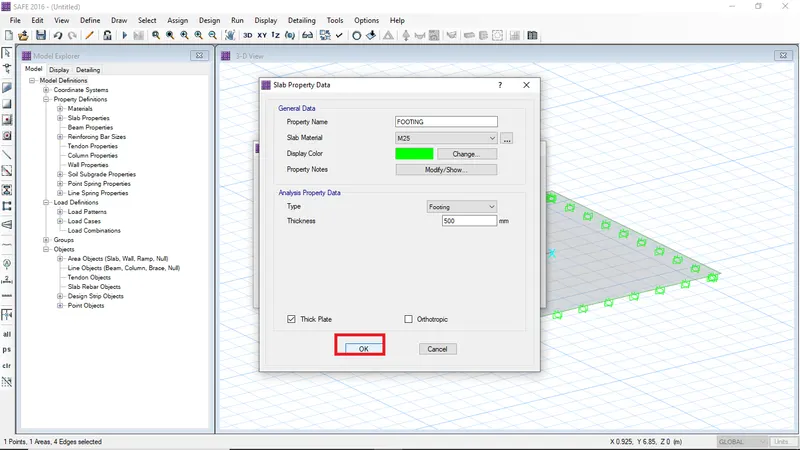
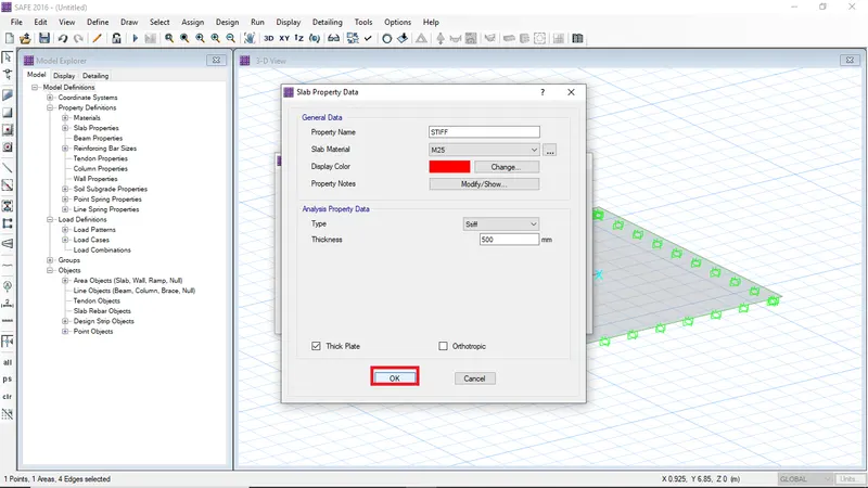
Select slab material as M25 concrete then click ok
-
After finishing modify click ok

-
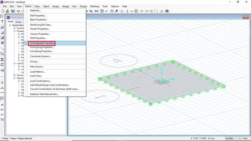
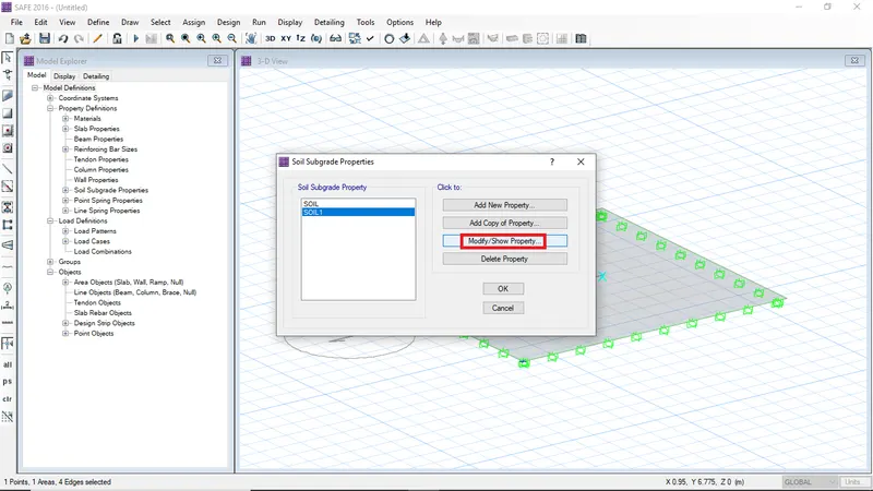
Create soil subgrade property from define soil subgrade property in define menu
-
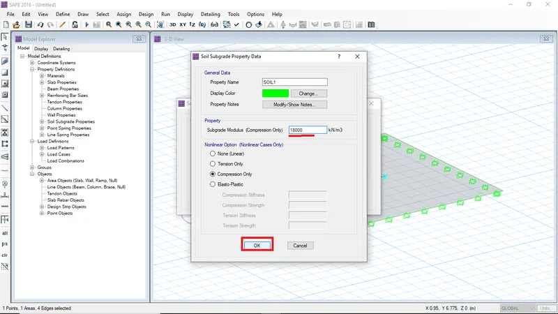
Change the subgrade modulus based on allowable deflection, In this 25 mm settlement is considered as maximum
-
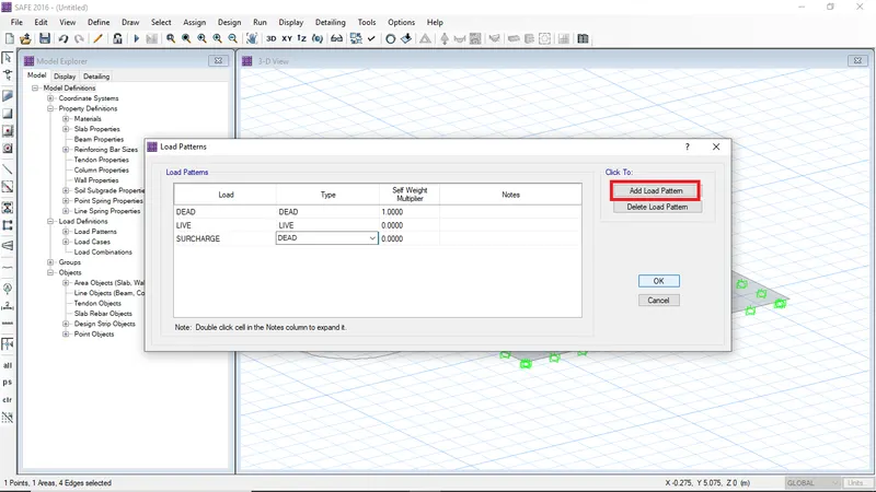
Add load patterns
-
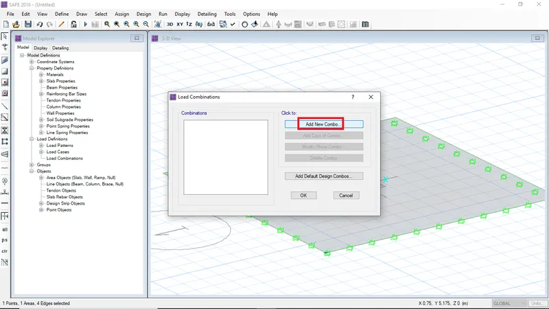
Then create load combinations
-
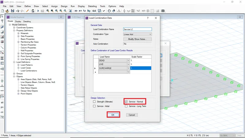
For service load combination enter scale factor as 1 then click ok
-
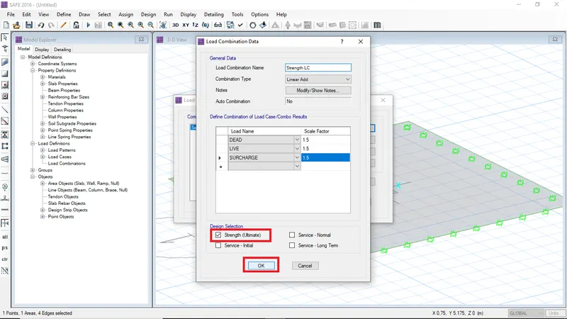
For strength load combination enter scale factor as 1.5
-
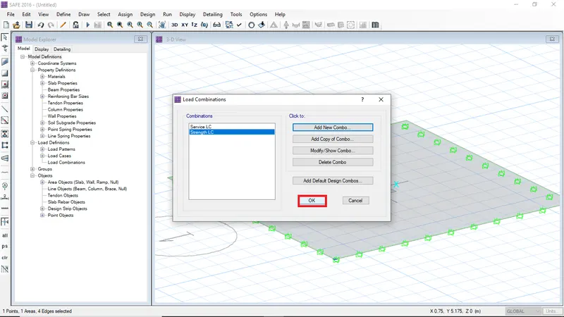
After finishing load combination click ok
-
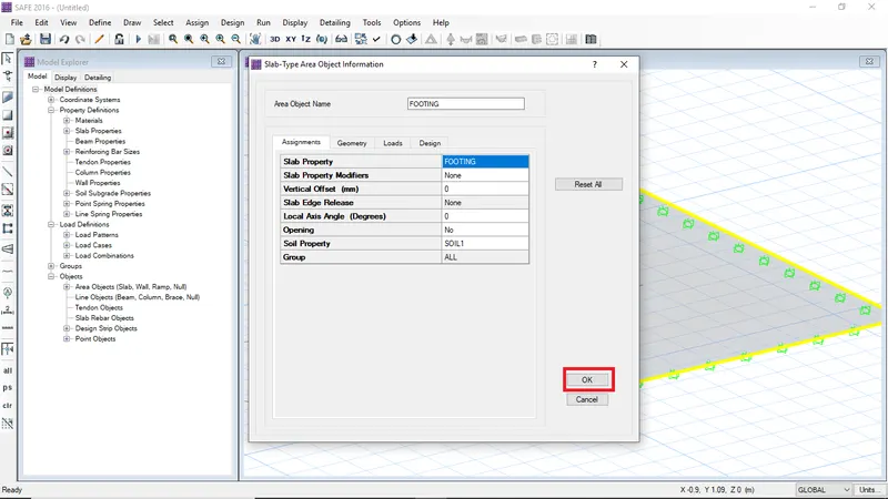
Once again check the assignments
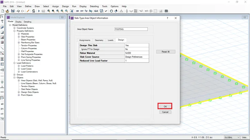
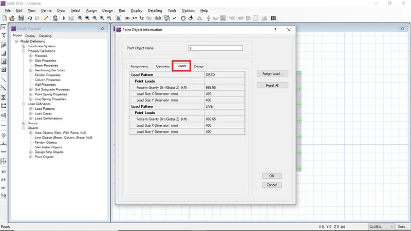
-
Go to draw and click on draw design strips to draw design strips
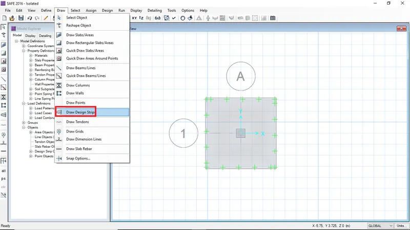
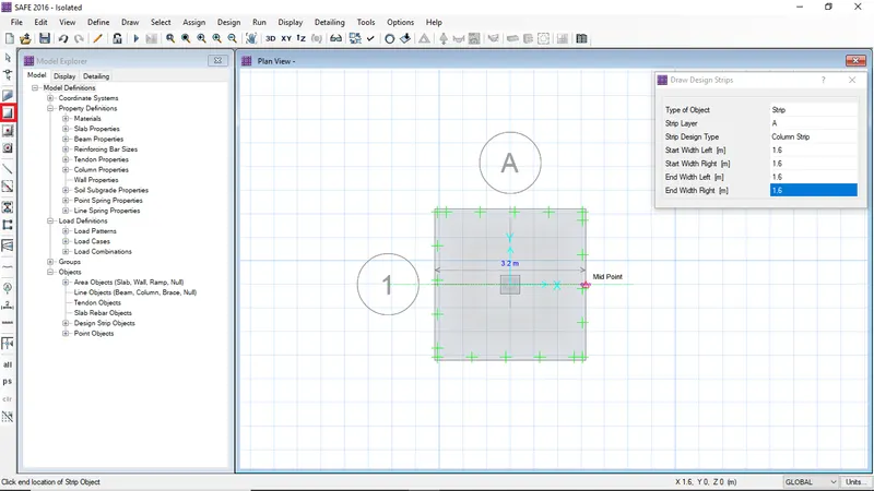
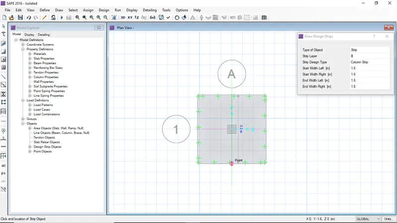
-
to view the drawn design strip check show width in display option
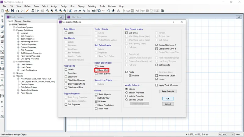
-
The design is visible and click on run analysis
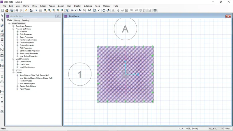
-
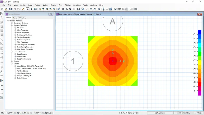
After analysis click on displacement to view displacement of footing under service load
-
The displacement is within limit
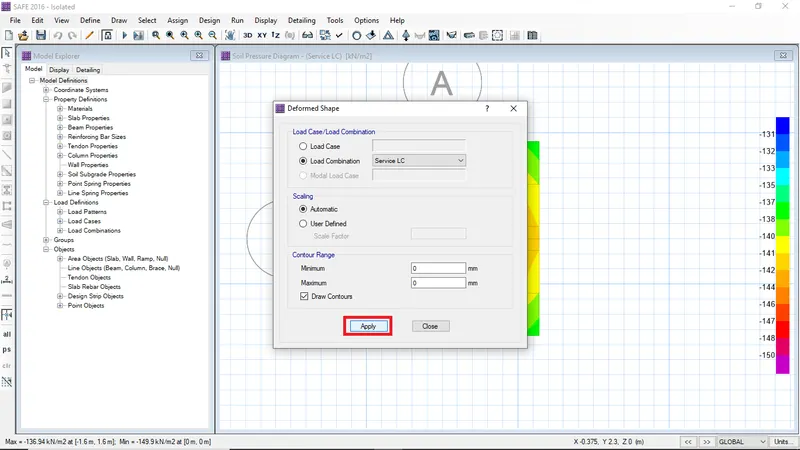
-
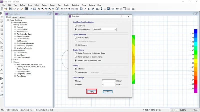
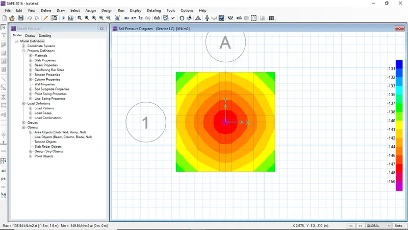
To view soil pressure, click on reaction for service load combination and click apply
-
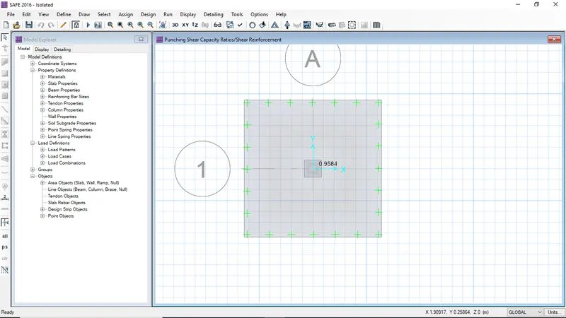
The design also pass punching shear check
-
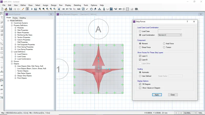
Bending moment diagram
-
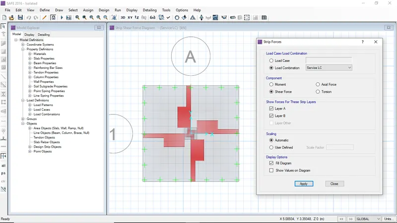
Shear force diagram
-
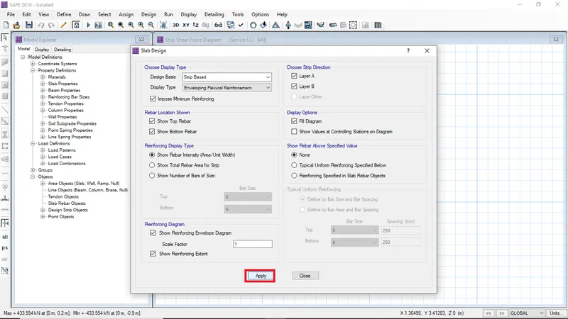
To ciew flexural design reinforcement details click slab design and select the strips and click ok
-
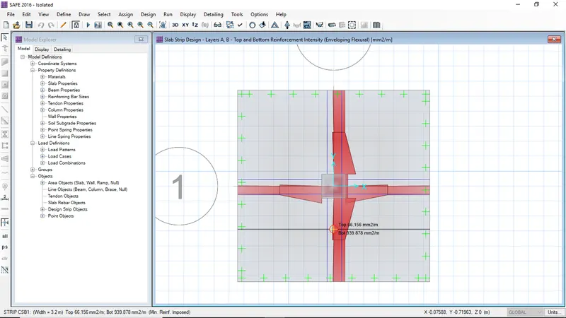
Top and bottom reinforcement details
RESULT
The isolated footing provided in week 11 challenge is modeled, analyzed and designed using SAFE 2016 software -
A column of size 600x600 carrying an unfactored gravity load (DL+LL) of 1175 KN is to be supported on pile cap, which ultimately transfers load to the piles underneath. Piles of 16 metres length and 500 mm diameter are to be used. Each pile has a load carrying capacity of 200 KN. Model, analyse and design the pile cap on SAFE to evaluate the following:
- Pile group to be used
- Depth of pile cap
- Longitudinal steel on top and bottom face in both directions
AIM:
To Model, analyze and design the pile cap on SAFE to evaluate the following:
- Pile group to be used
- Depth of pile cap
- Longitudinal steel on top and bottom face in both direction
Given data
-
Column size = 600 x 600 mm
-
Unfactored gravity load = 1175 kN
-
Pile length = 16 m
-
Pile diameter = 500 mm
-
Pile capacity = 200 kN
-
Number of piles required = `(1175*1.1) /200 = 6.5`
Provide 8 no of piles - Elastic modulus of M25 concrete = 25000 N/mm2
- Area of each pile = 196349.5 mm2
-
Spring constant = `(25000*196349.5)/16000 =306.8` kN/mm2
PROCEDURE: -
In the model initialization select design code IS 456-2000
-
Select units was selected as Metric
-
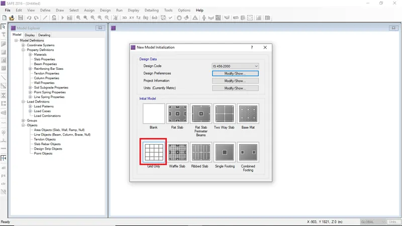
Then click on grid only to stsrt modeling
-
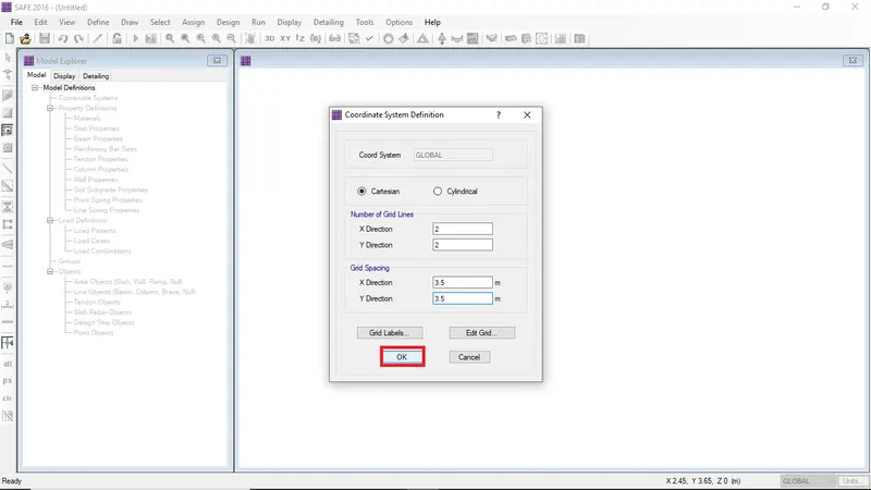
Enter the grid data
-
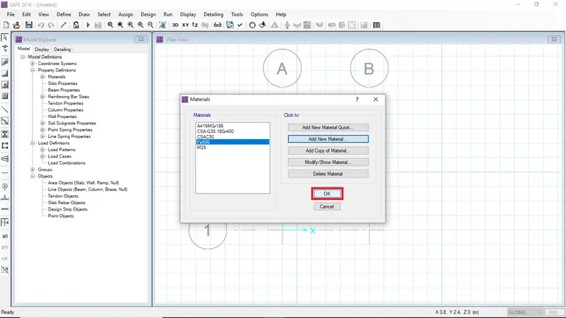
Define the material properties and click ok
-
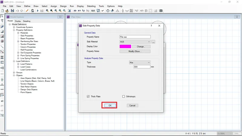
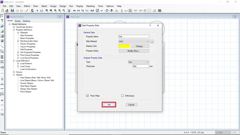
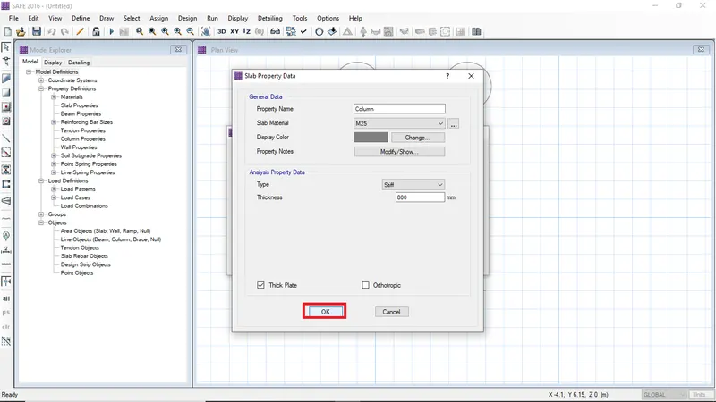
Create new slab properties and enter name, material and thickness then click ok.
-
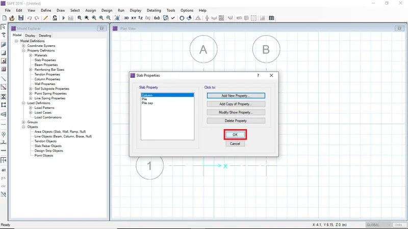
After defining slab property click ok to finish
-
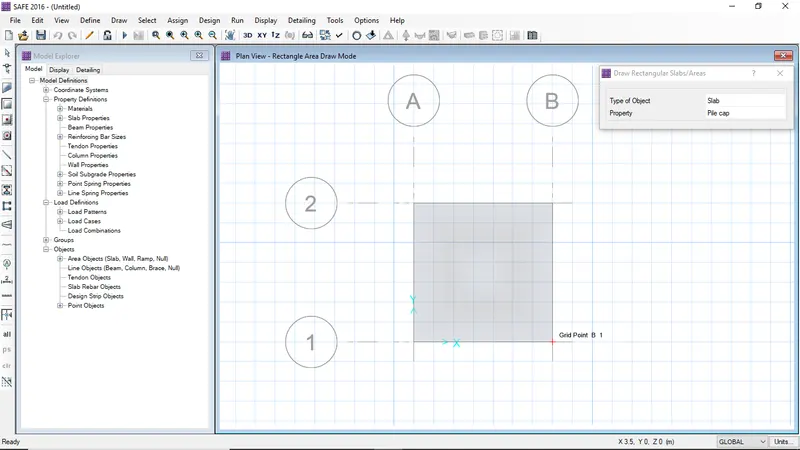
Click on draw slab and and select property as pile cap to draw
-
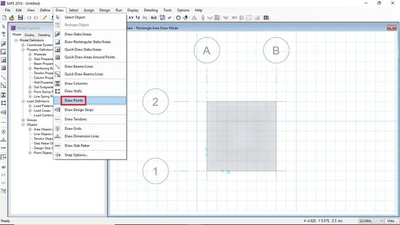
To draw piles create points from draw menu
-
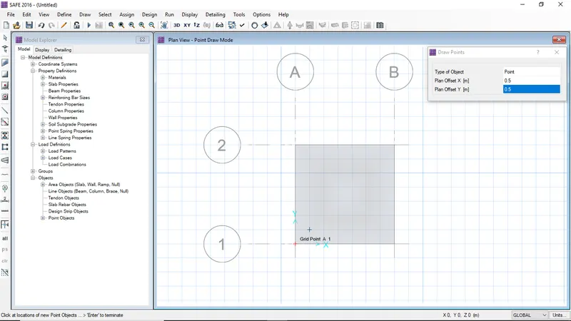
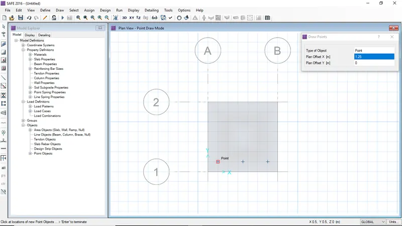
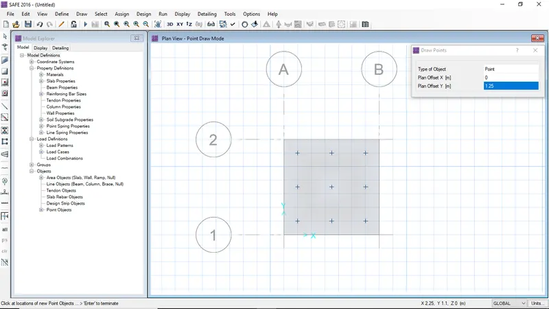
Create the points in the resoective pile locations
-
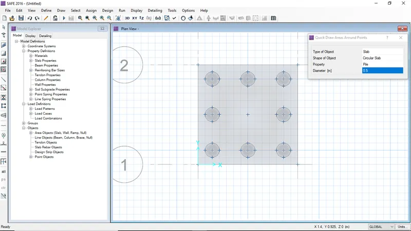
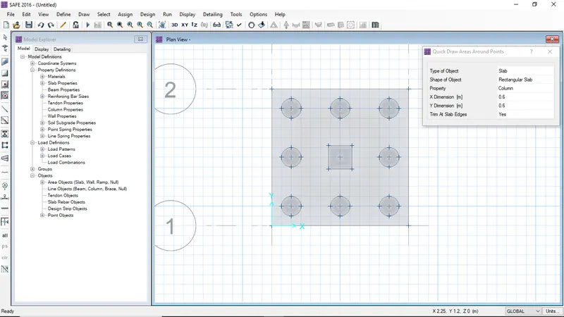
Click on quick draw areas to draw piles and column
-
Click on each point by entering their dimensions accordingly
-
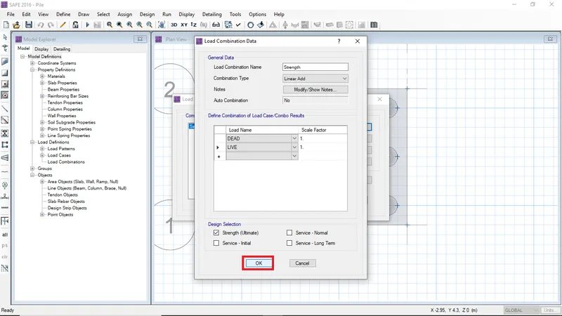
Create load combination then click ok
-
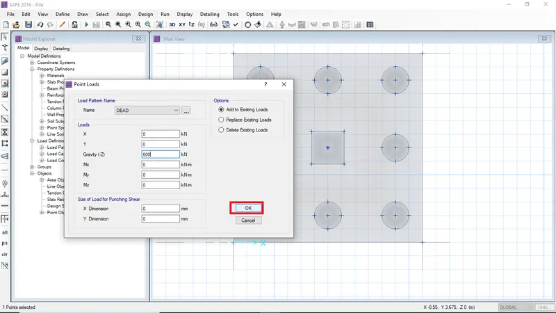
Assign the loads on the column point
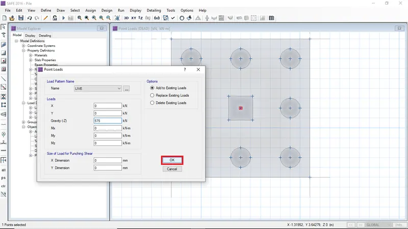
-
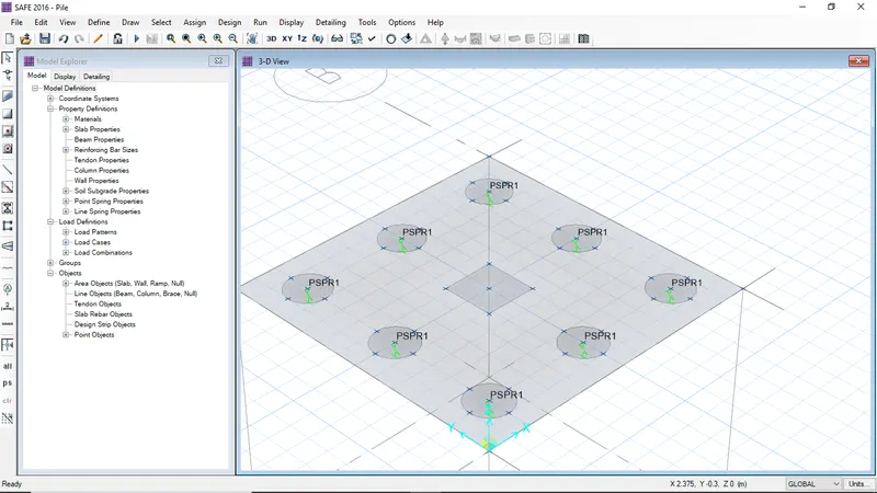
For the pile points need to assign springs
-
To assign spring, first select all the pile points
-
Then go to assign, click on point spring in support data
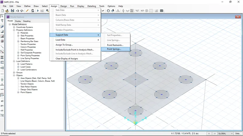
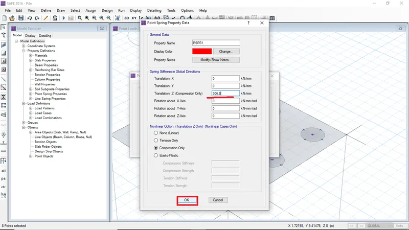
-
Click ok to assign
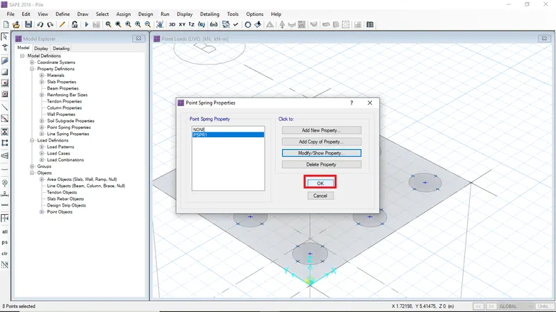
-
The assigned spring is visible in the screen
-
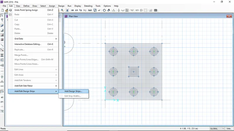
Click on auto design strips to draw strips by software
-
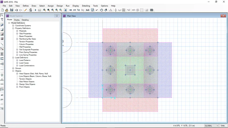
The drawn strips are visible
- Click on analysis and view results
-
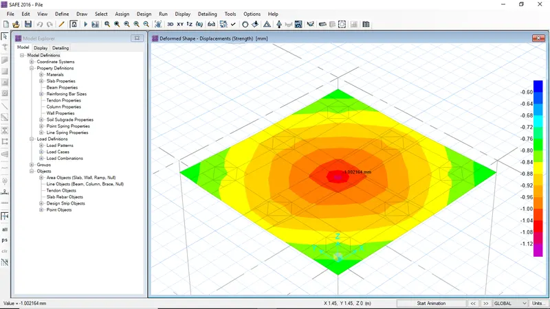
Maximum displacement was found to be 1.12 mm
-
The deflection is within limit, hence safe
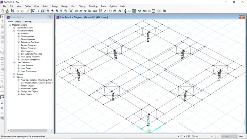
- As all the pile reaction forces are according within the limit.
- The pile reaction forces not exceeding 200 kN, Hence safe
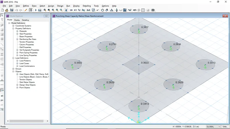
- Also, all the punching shear values are less than 1, So its safe
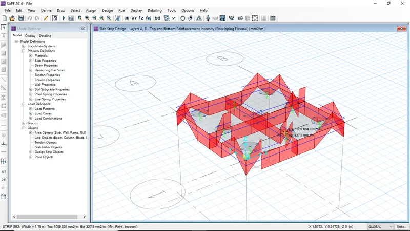
- Flexural reinforcement details
RESULT
The pile cap is modeled, analysed and designed using SAFE 2016