Centrifugal pump design and analysis
1. Aim:
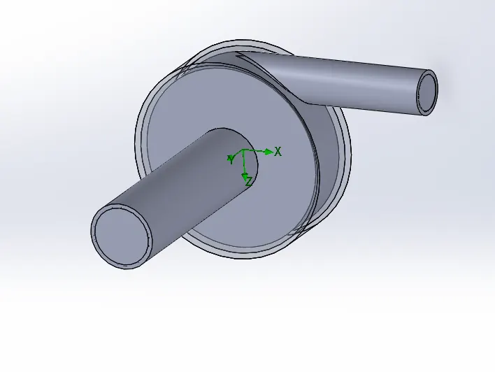
- To create a 3D model of a centrifugal pump.
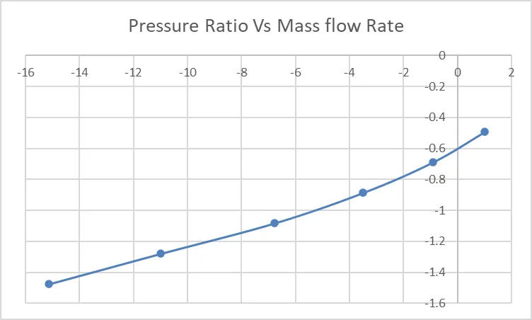
- Plot difference between pressure ratio and mass flow rate.
2. Introduction:
Centrifugal Pump:
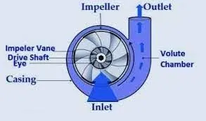
A centrifugal pump is a mechanical device designed to move fluid by means of the transfer of rotational energy from one or more driven rotors, called impellers. Fluid enters the rapidly rotating impeller along its axis and is cast out by centrifugal force along its circumference through the impeller’s vane tips. The action of the impeller increases the fluid’s velocity and pressure and also directs it towards the pump outlet. The pump casing is specially designed to constrict the fluid from the pump inlet, direct it into the impeller and then slow and control the fluid before discharge.
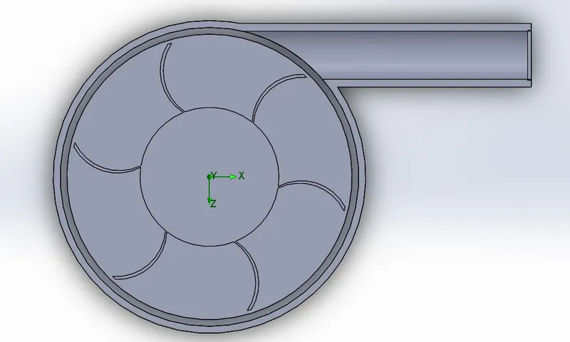
The impeller is the key component of a centrifugal pump. It consists of a series of curved vanes. These are normally sandwiched between two discs (an enclosed impeller). For fluids with entrained solids, an open or semi-open impeller. Fluid enters the impeller at its axis and exits along the circumference between the vanes. The impeller, on the opposite side to the eye, is connected through a drive shaft to a motor and rotated at high speed (typically 500-5000rpm). The rotational motion of the impeller accelerates the fluid out through the impeller vanes into the pump casing. There are two basic designs of pump casing: volute and diffuser. The purpose of both designs is to translate the fluid flow into a controlled discharge at pressure. In a volute casing, the impeller is offset, effectively creating a curved funnel with an increasing cross-sectional area towards the pump outlet. This design causes the fluid pressure to increase toward the outlet. The same basic principle applies to diffuser designs. In this case, the fluid pressure increases as fluid are expelled between a set of stationary vanes surrounding the impeller. Diffuser designs can be tailored for specific applications and can therefore be more efficient. Volute cases are better suited to applications involving entrained solids or high viscosity fluids when it is advantageous to avoid the added constrictions of diffuser vanes. The asymmetry of the volute design can result in greater wear on the impeller and drive shaft.
3. Flow Simulation:
3.1 Baseline Parameters:
- Analysis type: Internal
- Fluid used: Water
- Type of flow: Laminar and turbulent
- Rotation Type: Local Region Averaging
3.2 Procedure:
- Create a 3d model of a centrifugal pump
- Go to flow simulation create lids, give the input parameters select water as fluid type.
- Then add the boundary conditions- for the first rotation, select the region of rotation at 1000 rad/sec, enter the inlet as environment pressure and outlet as the velocity of 10 m/s.
- The surface goal is to set the inlet and outlet for the total pressure and add the surface mass flow rate.
- Set the mesh grid as 3 automatically and advanced channel refinement.
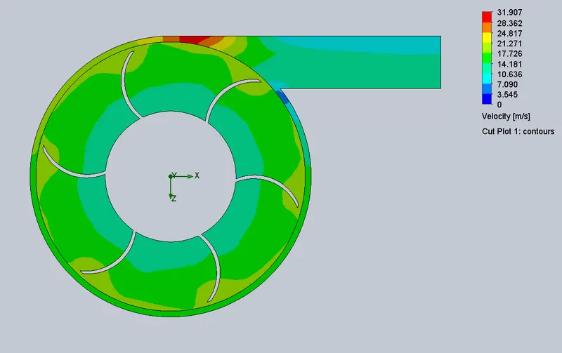
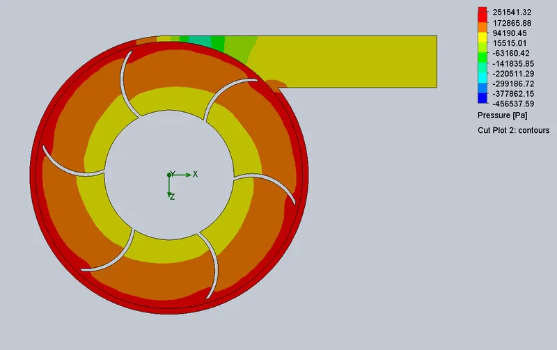
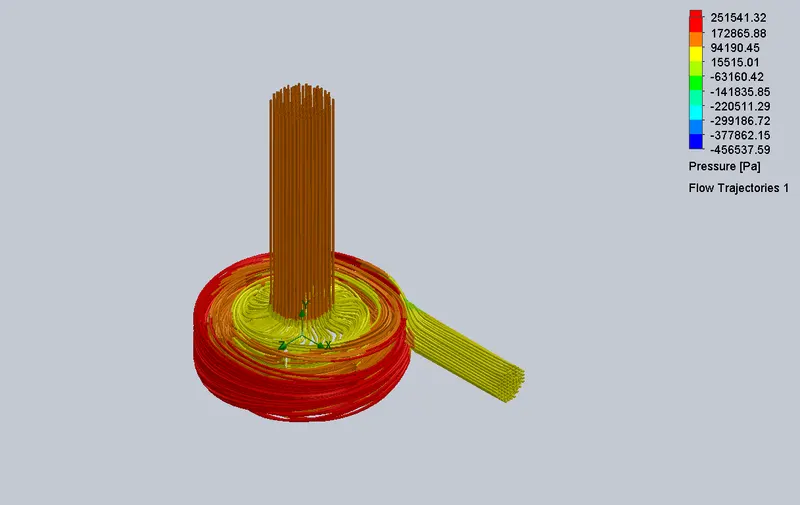
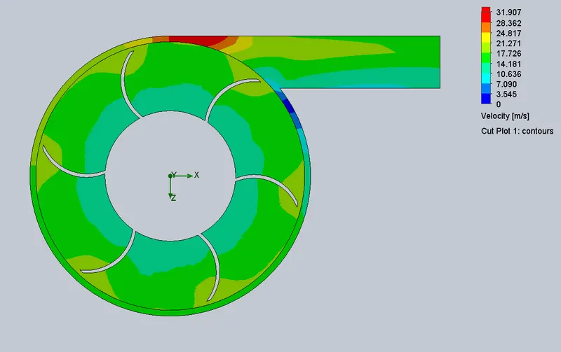
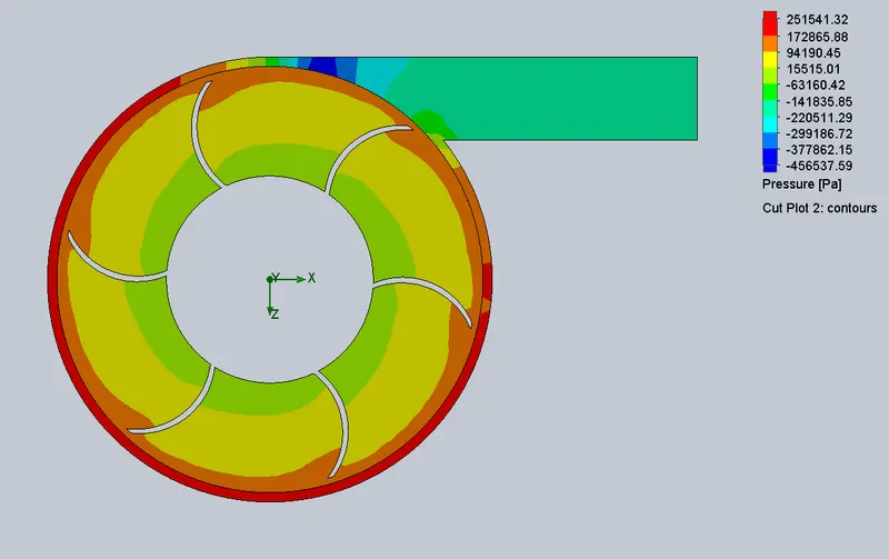
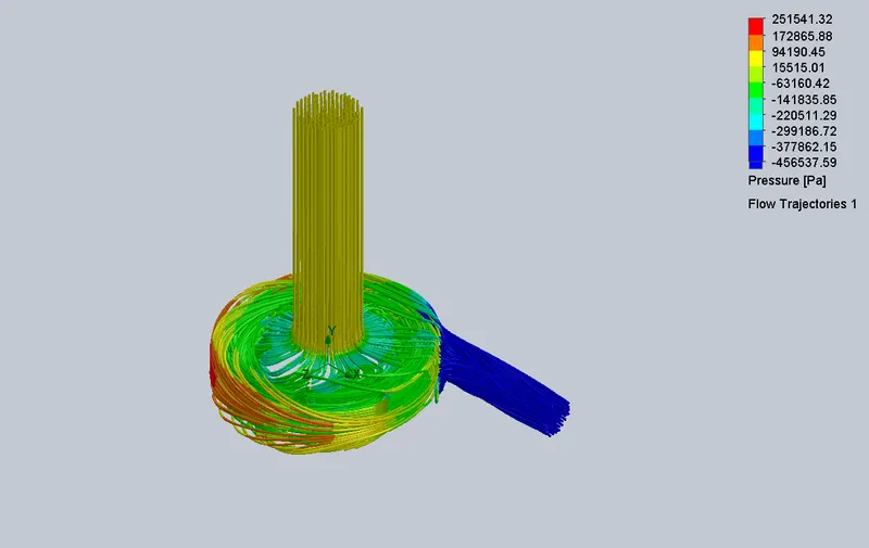
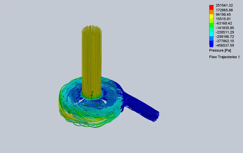
- Run the simulation and the cut plot is created for velocity and flow trajectory.
Sectional view:
4. Results
Design Point: 1; V=10 m/s
Velocity Plot
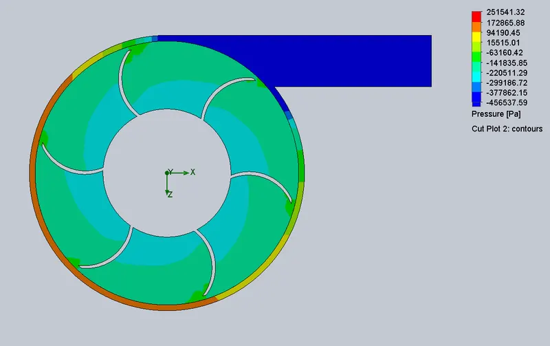
Pressure Plot
Flow Trajectory
Design Point: 2; V=14 m/s
Velocity Plot
Pressure Plot
Flow Trajectory
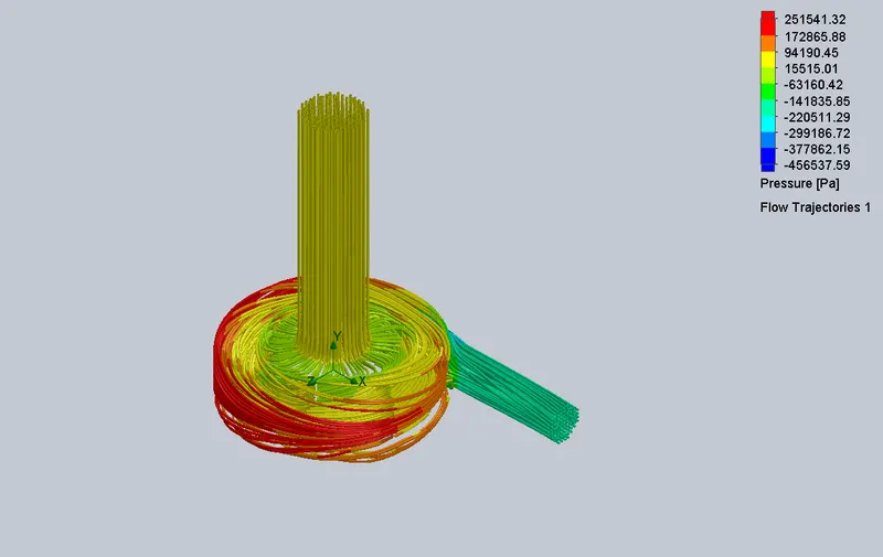
Design Point: 3; V=18 m/s
Velocity Plot
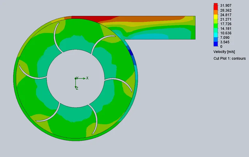
Pressure Plot
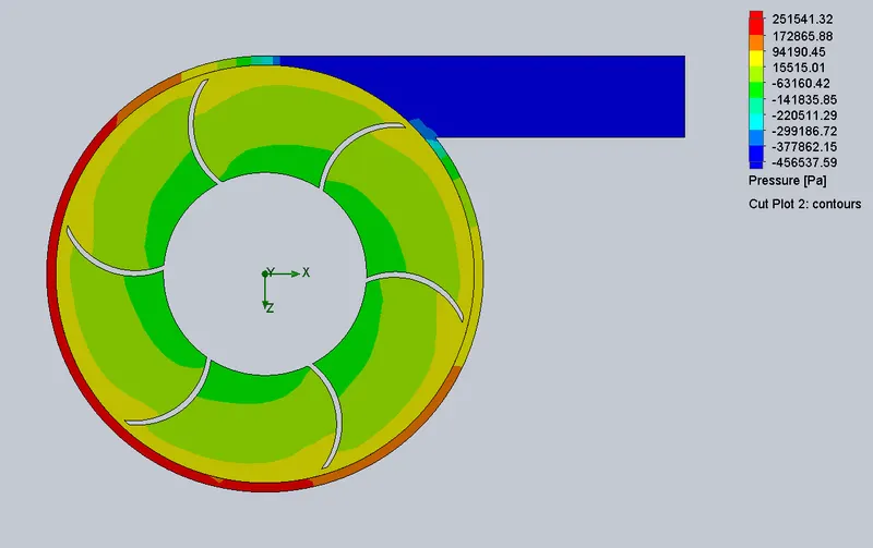
Flow Trajectory
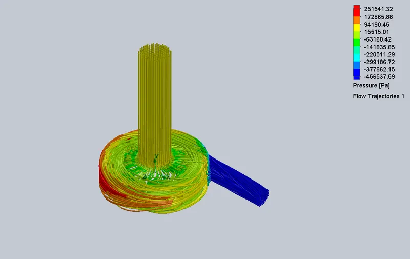
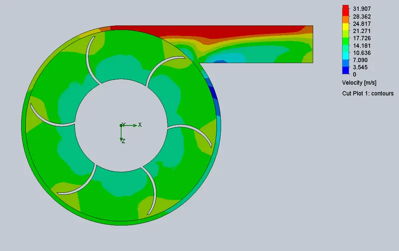
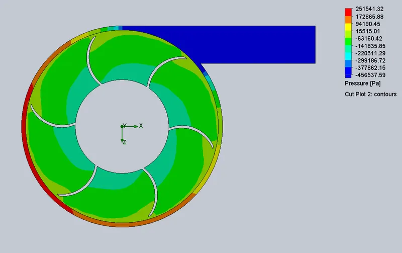
Design Point: 4; V=22 m/s
Velocity Plot
Pressure Plot
Flow Trajectory
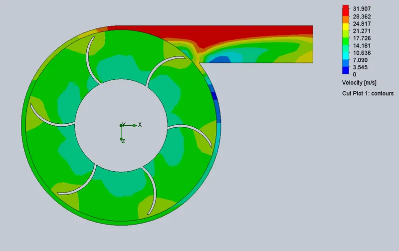
Design Point: 5; V=26 m/s
Velocity Plot
Pressure Plot
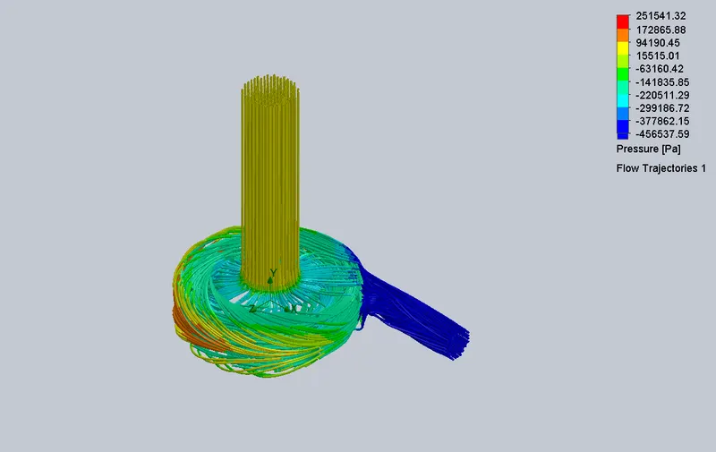
Flow Trajectory
Design Point: 6; V=30 m/s
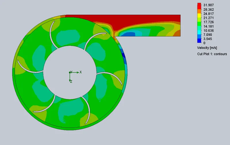
Velocity Plot
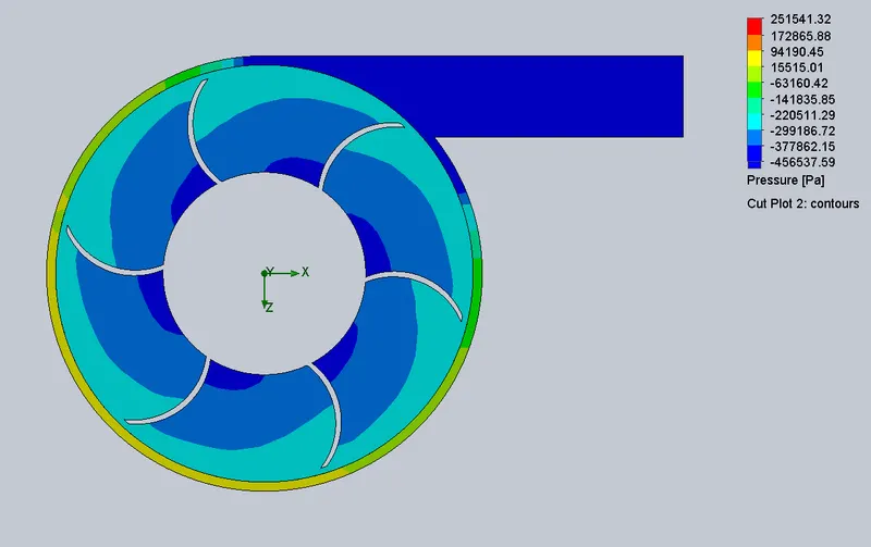
Pressure Plot
Flow Trajectory
| Goal (Value) | Design Point 1 | Design Point 2 | Design Point 3 | Design Point 4 | Design Point 5 | Design Point 6 |
| Velocity normal to face (Outlet Velocity 1) [m/s] | 10 | 14 | 18 | 22 | 26 | 30 |
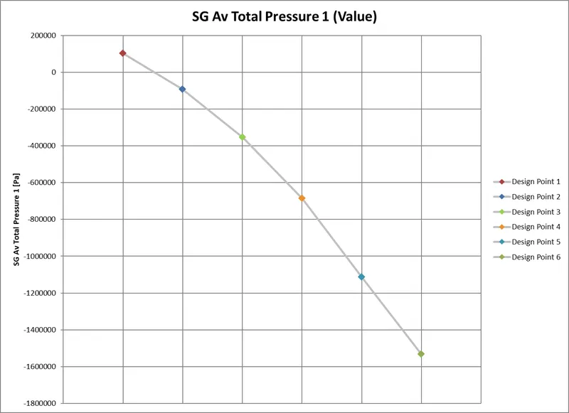
| SG Av Total Pressure 1 [Pa] | 102385.3116 | -92808.41389 | -354082.0076 | -686300.8553 | -1113513.384 | -1532383.814 |
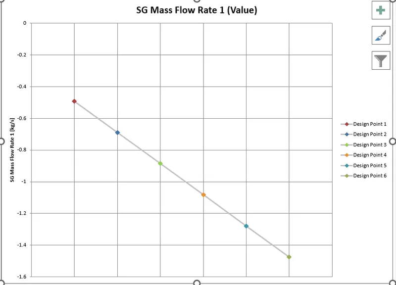
| SG Mass Flow Rate 1 [kg/s] | -0.491898927 | -0.688657944 | -0.88540757 | -1.082147646 | -1.278874728 | -1.475597232 |
6. Conclusion
- Increase in outlet velocity the mass flow rate showed a linear variation in a negative direction.
- Pressure ratio Vs Velocity concludes that velocity increases and pressure decreases.
- In pressure ratio Vs Mass flow rate, the pressure ratio value decreases up to a certain limit after that pressure will become constant.
Here is the link to the part model
https://drive.google.com/drive/folders/1qSY2dWY12tpQ6mxDOsiZpaMdcGmHmyYO?usp=sharing