Flow over an NACA0017 airfoil using SolidWorks.
Aim:
- To model the flow over a NACA0017 symmetrical airfoil.
- To compare the lift and drag forces, for angle of attacks 0,2,4,6,8 & 10.
- To find out stall condition for this symmetrical airfoil by raising angle of attack further.
Introduction:
A stationary fluid exerts only normal pressure forces on the surface of a body immersed in it. A moving fluid, however, also exerts tangential shear forces on the surface because of the no-slip condition caused by viscous effects. Both of these forces, in general, have components in the direction of flow, and thus the drag force is due to the combined effects of pressure and wall shear forces in the flow direction. The components of the pressure and wall shear forces in the direction normal to the flow tend to move the body in that direction, and their sum is called lift.
The wings of airplanes are shaped and positioned specifically to generate lift with minimal drag. This is done by maintaining an angle of attack during cruising. The shape of the wings is called airfoil.
The pressure difference between the top and bottom surfaces of the wing generates an upward force that tends to lift the wing and thus the airplane to which it is connected. For slender bodies such as wings, the shear force acts nearly parallel to the flow direction, and thus its contribution to the lift is small. The drag force for such slender bodies is mostly due to shear forces (the skin friction).
It should be kept in mind that some devices such as spoilers and inverted airfoils on racing cars are designed for the opposite purpose of avoiding lift or even generating negative lift to improve traction and control.
For airfoils, the contribution of viscous effects to lift is usually negligible since the body is streamlined and wall shear is parallel to the surfaces and thus nearly normal to the direction of lift.
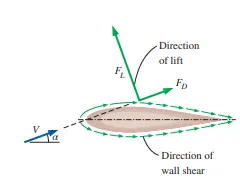
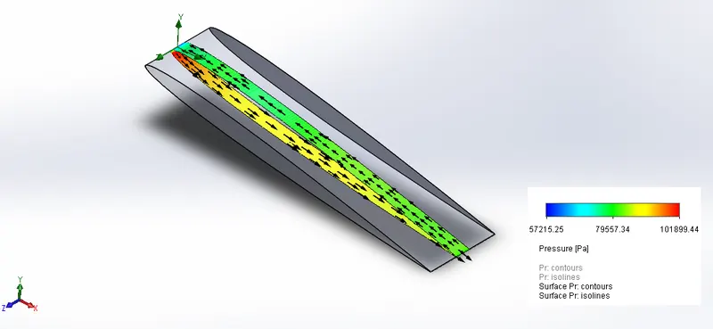
Therefore, lift in practice can be approximated as due entirely to the pressure distribution on the surfaces of the body, and thus the shape of the body has the primary influence on lift. Then the primary consideration in the design of airfoils is minimizing the average pressure at the upper surface while maximizing it at the lower surface. The Bernoulli equation can be used as a guide in identifying the high- and low-pressure regions: Pressure is low at locations where the flow velocity is high, and pressure is high at locations where the flow velocity is low.
In order to design an Aircraft wing, there are two basic things we need to consider:
(i). Airfoil of our wing –
Different types of Airfoil are shown below,
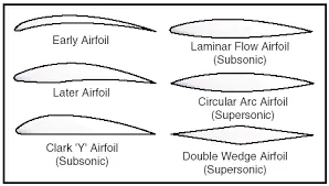
For this project we will use NACA0017 airfoil which is a symmetrical airfoil with rectangular planform.
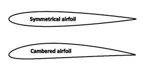
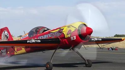
In symmetrical airfoil, the mean camber line is the same as the cord line. In a straight flight this airfoil shape will generate no lift, since pressure decrease is same on the top and the bottom of the airfoil. But many aircrafts use symmetrical airfoil, so how do they generate lift? By changing the orientation of the symmetrical airfoil to the airflow, an asymmetric flow pattern is created. This asymmetric flow pattern, with streamline squeezed together tighter on the top create velocity and pressure differences, which produce lift. Symmetrical airfoil is commonly used in aerobatic airplanes, as it allows the pilot to fly upside down and perform complex manoeuvres.
As shown below, the orientation of symmetrical airfoil is changed in an aerobatic aircraft by lowering the height at the back, to generate lift. Additionally, movable surfaces like Aileron also help in changing the camber and thus increasing or decreasing lift.
(ii). Wing Planform –
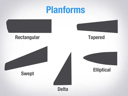
This is the shape of the wing when viewed from the top. E.g., rectangular, delta (triangular shaped), tapered or elliptical.
A wing in the shape of a rectangle is very common on small general aviation airplanes. An elliptical shape or tapered wing can also be used, but these do not have as desirable a stall characteristic. For airplanes that operate at high subsonic speeds, sweptback wings are common, and for supersonic flight, a delta shape might be used.
Each of these shapes have different stall characteristics. For example, rectangular wing will start to stall near the fuselage and as we plane gets slower the region of stall will spread outwards. Whereas for elliptical wing the stall will start near the trailing edge of entire wing and then propagate forward. This stall characteristic will give rectangular airfoil more wing control since the aileron are not completely inside the stall zone.
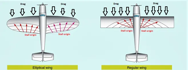
If we look at their drag characteristic then we will find out the leading edge of the rectangular airfoil is perpendicular to the air flow thus facing most drag. Where as in other shapes like tapered or elliptical the air drag is not perpendicular, hence experiencing less drag.
Airfoil Terminologies:
Camber
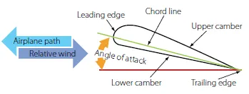
The camber of a wing is the curvature which is present on top and bottom surfaces. The camber on the top is much more pronounced, unless the wing is a symmetrical airfoil, which has the same camber top and bottom. The bottom of the wing, more often than not, is relatively flat. The increased camber on top is what causes the velocity of the air to increase and the static pressure to decrease. The bottom of the wing has less velocity and more static pressure, which is why the wing generates lift.
Chord Line
The chord line is an imaginary straight line running from the wing’s leading edge to its trailing edge. The angle between the chord line and the longitudinal axis of the airplane is known as the angle of incidence.
Angle of Attack
The angle between the chord line and the relative wind is the angle of attack. As the angle of attack increases, the lift on the wing increases. If the angle of attack becomes too high, the airflow can separate from the wing and the lift will reduce. When this occurs, a condition known as a stall takes place.
Steps Taken:
Modelling airfoil:
Side view

Top view
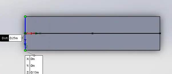
Planform area = 1m * 0.25m = 0.25m^2
- Using ‘Flow Simulation’ tab:
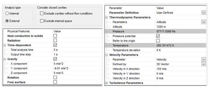
- Setting up Flow simulation Project using ‘Analysis Wizard’.
It asks us a series of questions that sets up majority of our analysis. In Analysis wizard we choose type and analysis and select fluid from extensive database.
Selecting Unit system as SI.
Analysis type = External.
Check Time dependent analysis with analysis time 5sec.
Turing Gravity on in Y-component = -9.81 m/s^2.
Fluid = Air.
Flow type = Laminar and Turbulent.
In Thermodynamic Properties, select, Altitude = 1200m.
Velocity in X-direction = 155m/s.
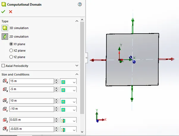
- Selecting computational domain as shown below:
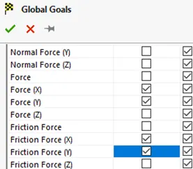
- Setting up goal:
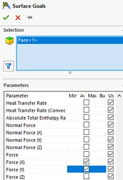
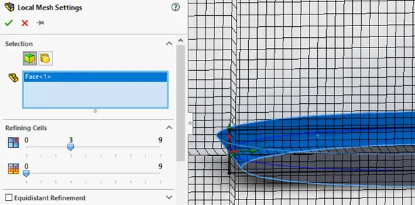
- Refining mesh at surface:
Results:
- For 0-degree angle of Attack:
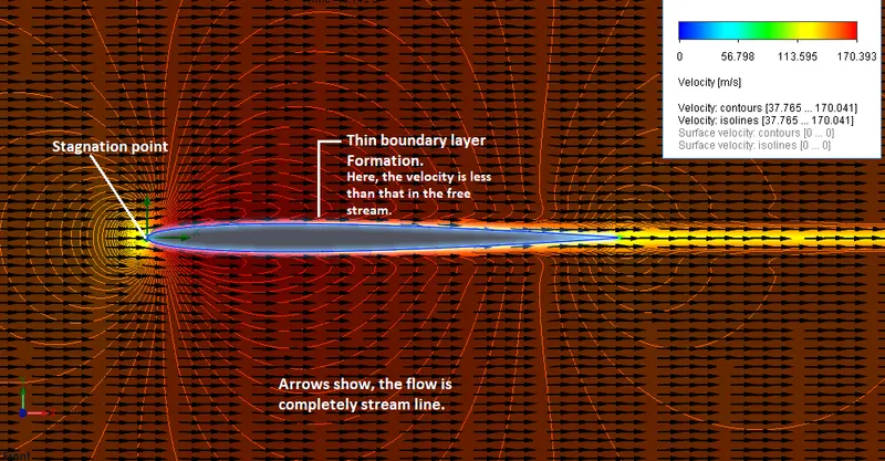
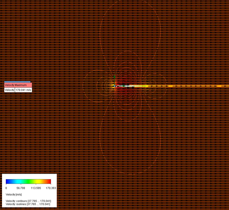
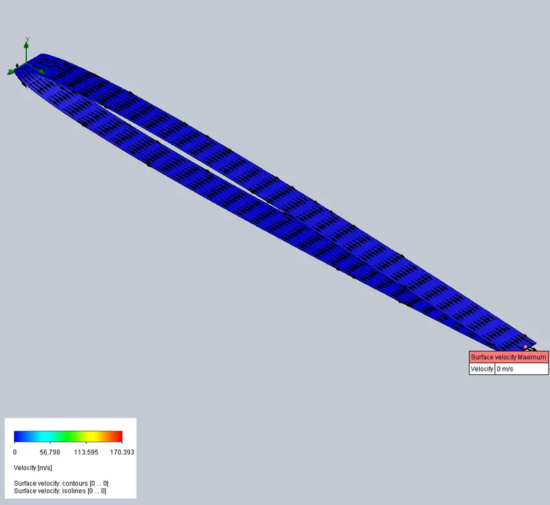
Velocity Plots (Cut-plot & Surface plot):
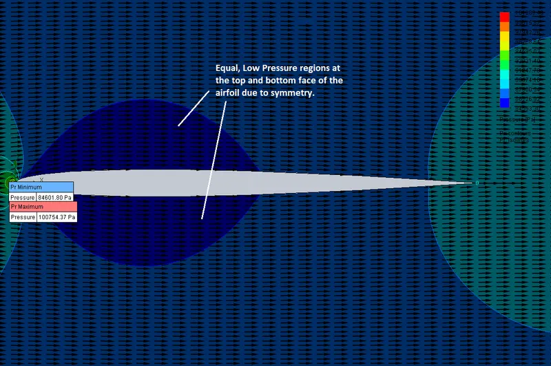
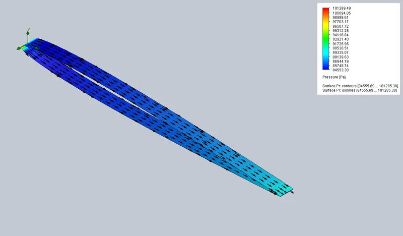
Pressure Plots (Cut-plot & Surface plot): symmetry
- For 2-degree angle of Attack:
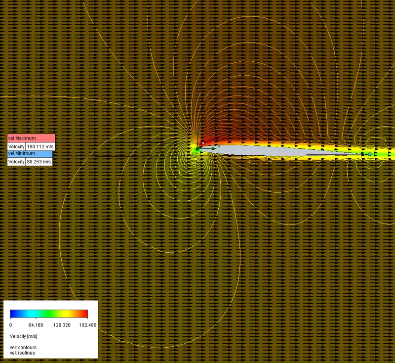
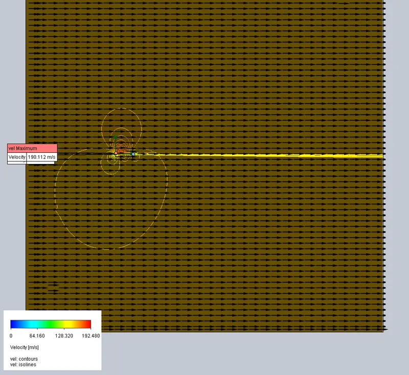
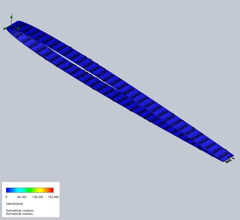
Velocity Plots (Cut-plot & Surface plot):
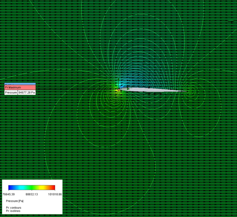
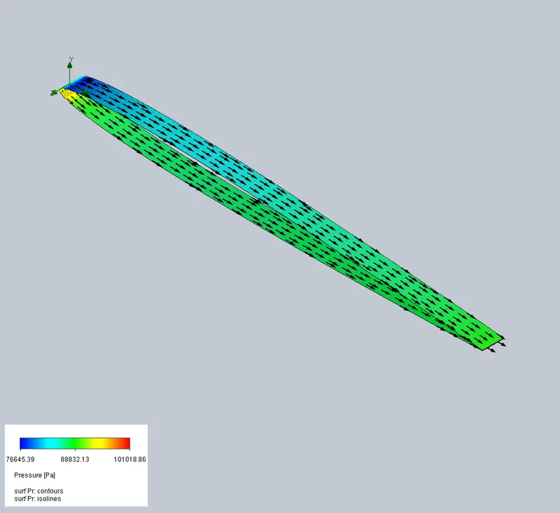
Pressure Plots (Cut-plot & Surface plot):
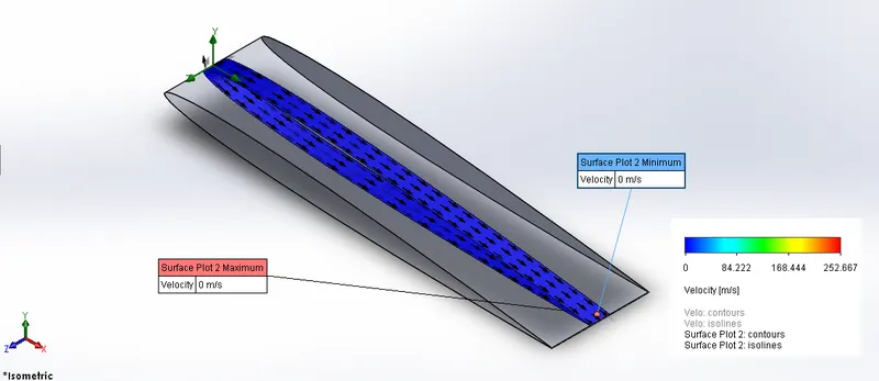
- For 4-degree angle of Attack:
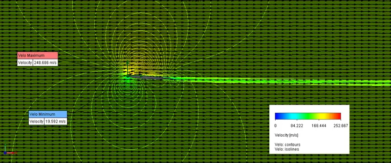
Velocity Plots (Cut-plot & Surface plot):
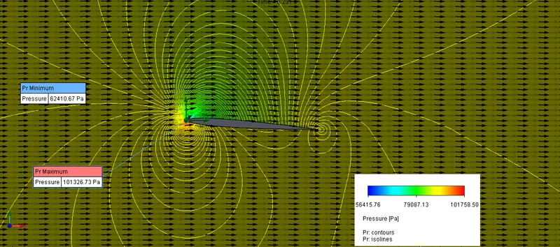
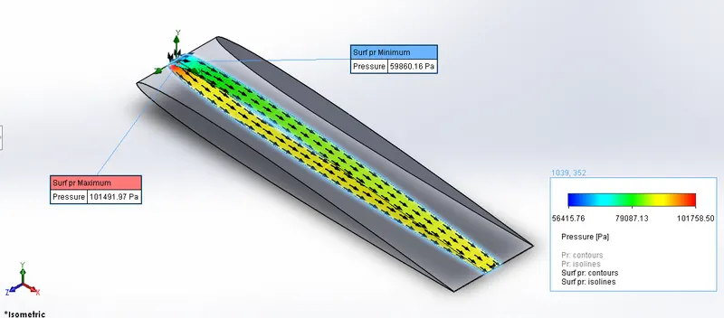
Pressure Plots (Cut-plot & Surface plot):
- For 6-degree angle of Attack:
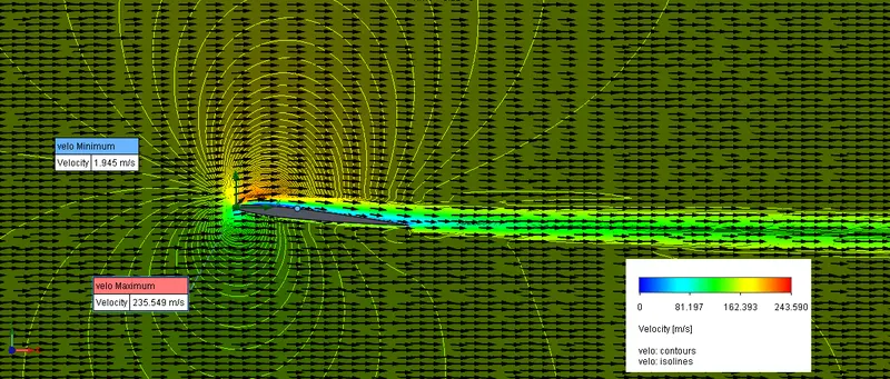
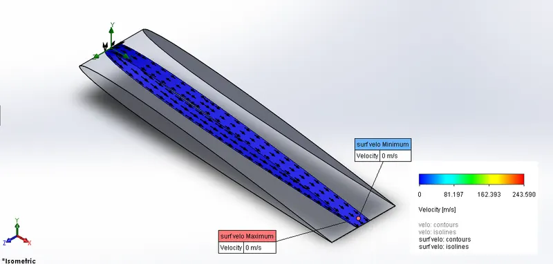
Velocity Plots (Cut-plot & Surface plot):
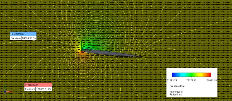
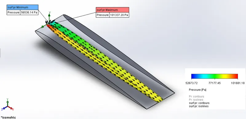
Pressure Plots (Cut-plot & Surface plot):
- For 8-degree angle of Attack:
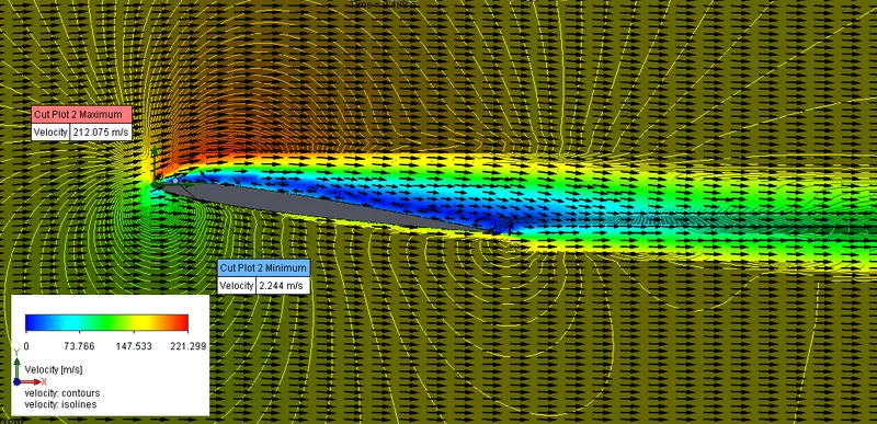
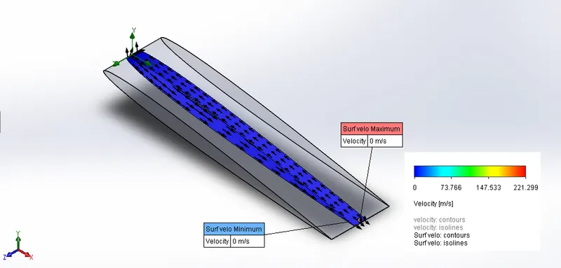
Velocity Plots (Cut-plot & Surface plot):
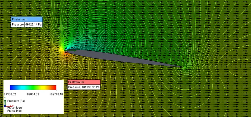
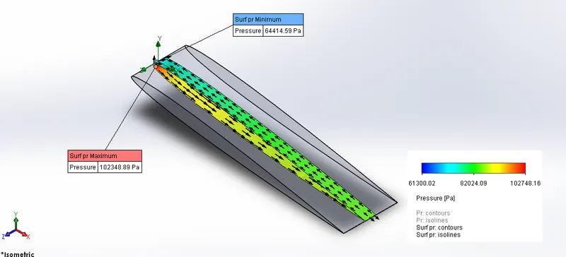
Pressure Plots (Cut-plot & Surface plot):
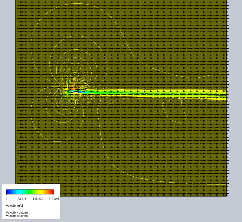
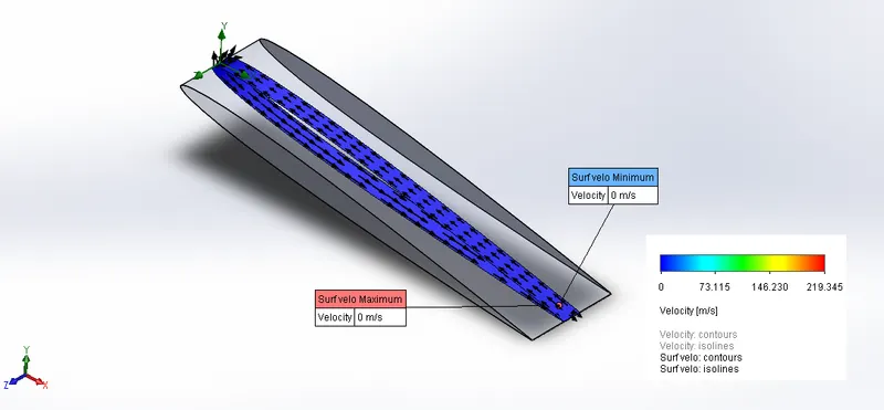
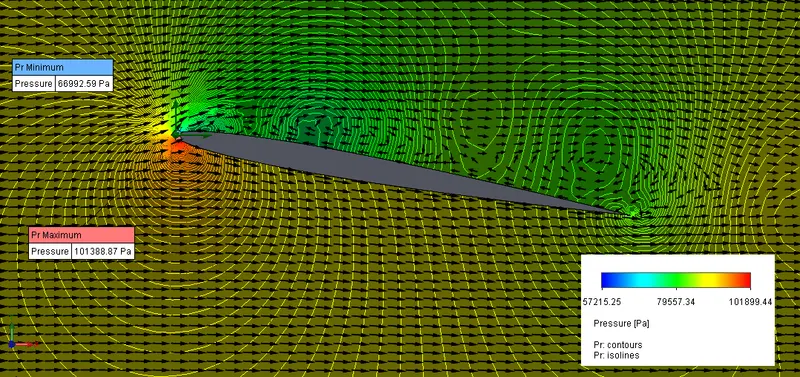
- For 10-degree angle of Attack:
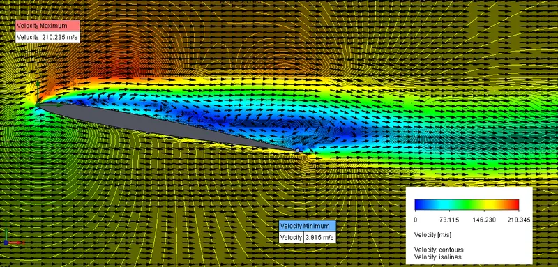
Velocity Plots (Cut-plot & Surface plot):
Pressure Plots (Cut-plot & Surface plot):
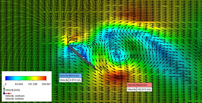
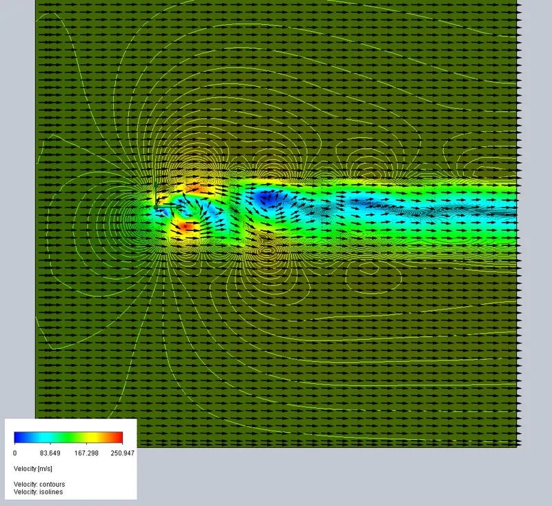
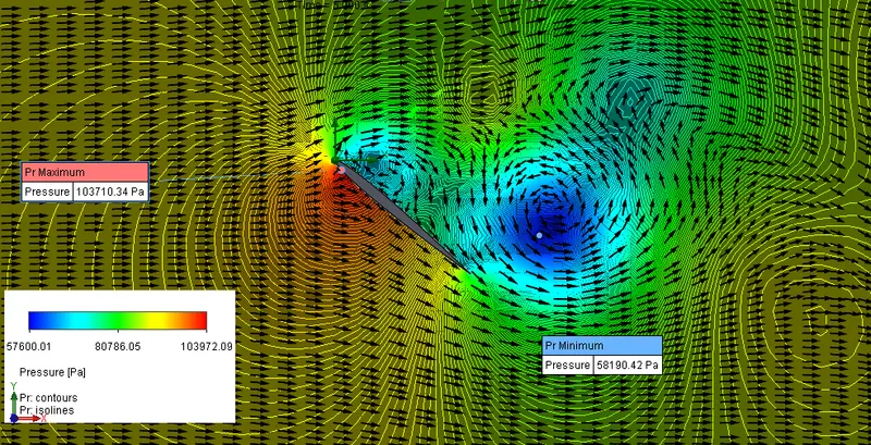
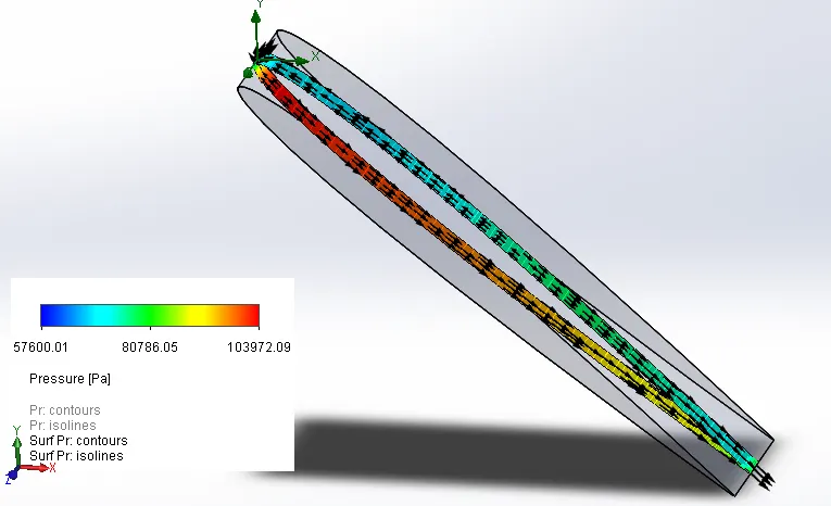
- For 40-degree angle of Attack:
Velocity Plots (Cut-plot & Surface plot):
Pressure Plots (Cut-plot & Surface plot):
- For 45-degree angle of Attack:
Velocity Plots (Cut-plot only):
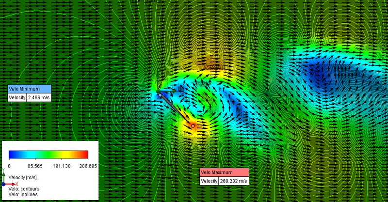
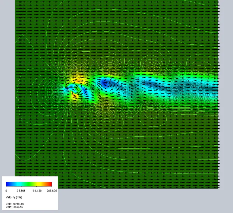
Pressure Plots (Cut-plot & Surface plot):
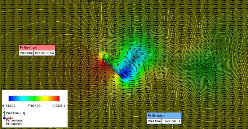
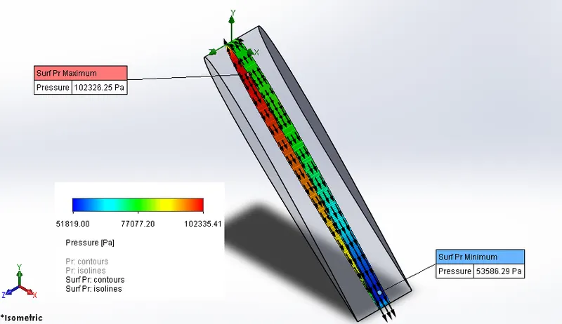
- For 50-degree angle of Attack:
Velocity Plots (Cut-plot only):
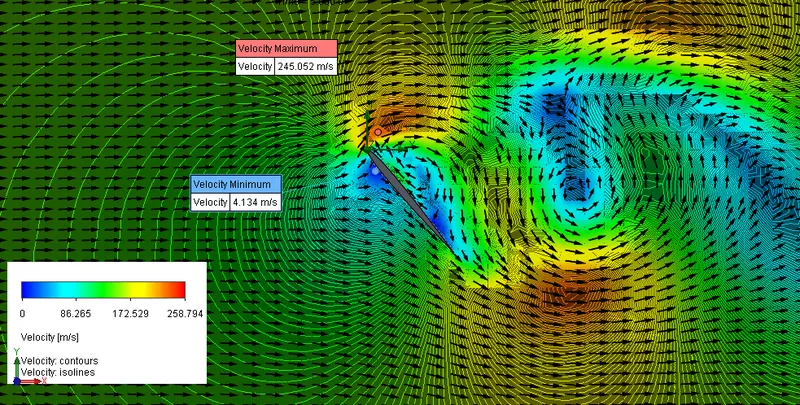
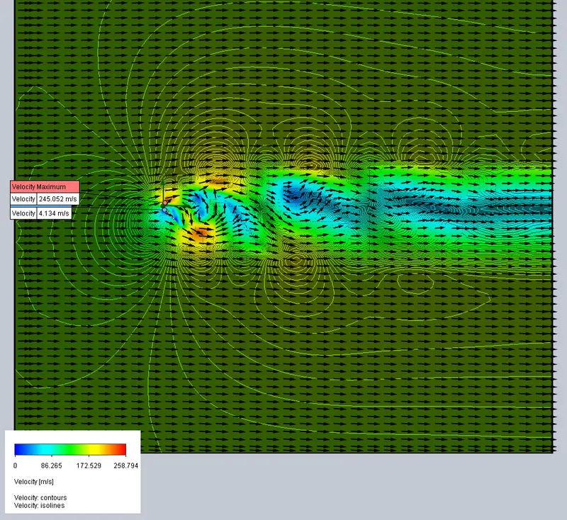
Pressure Plots (Cut-plot only):
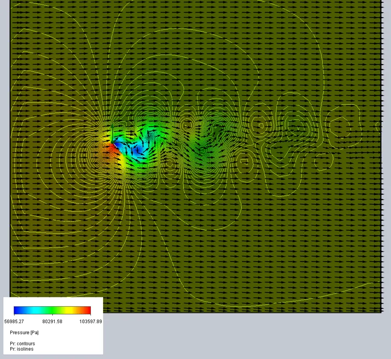
- Data Table for Forces along x-axis (Direction of flow) and y-axis:
|
Angle of Attack (in degrees) |
Force (X) (N) |
Lift (N) |
Friction (x) (N) |
Friction (y) (N) |
Total Drag (N) |
|
0 degree |
4.226110272 |
-0.03711323 |
3.413557353 |
5.80507E-05 |
7.63 |
|
2 degrees |
6.732744826 |
140.6428606 |
3.276441457 |
-0.09263344 |
10.00 |
|
4 degrees |
9.002859985 |
286.9683194 |
3.186012614 |
-0.11314829 |
12.18 |
|
6 degrees |
26.62567054 |
369.9652522 |
1.713563387 |
-0.08162072 |
28.33 |
|
8 degrees |
57.22425917 |
419.1620769 |
1.381649792 |
-0.08742422 |
58.6 |
|
10degrees |
81.08962195 |
448.3526847 |
1.422019931 |
-0.13364045 |
82.5 |
|
17 degrees |
156.9411603 |
483.9714921 |
1.443617803 |
-0.33004301 |
158.38 |
|
20 degrees |
260.6992677 |
667.2648408 |
1.52601193 |
-0.449277 |
262.21 |
|
25 degrees |
351.5251527 |
698.0115505 |
1.621544504 |
-0.65924999 |
353.14 |
|
30 degrees |
604.0673184 |
1013.509258 |
0.409751405 |
-0.11137035 |
604.46 |
|
40 degrees |
742.2468967 |
889.89134 |
0.791168979 |
-0.6258078 |
743.03 |
|
45 degrees |
865.4185089 |
812.6694065 |
2.594921644 |
-2.54739868 |
868.00 |
|
50 degrees |
1244.369646 |
1078.600912 |
0.390878903 |
-0.32883073 |
1244.75 |
Note:- Total Drag force is obtained by adding Pressure Drag (Force (x)) and Friction (x) Drag.
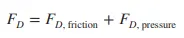
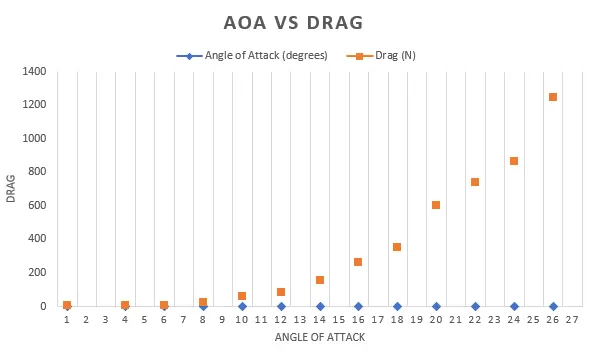
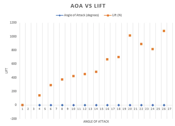
Graphs of Drag and Lift force with respect to angle of attack (AOA):
Observation:
Note:- AOA = Angle of attack.
- Cross-flow over a Airfoil exhibits complex flow patterns. The fluid approaching the airfoil branches out and encircles the airfoil, forming a boundary layer that wraps around the airfoil. The fluid particles strike the airfoil at the stagnation point, bringing the fluid to a complete stop and thus raising the pressure at that point. The pressure decreases in the flow direction on the camber of the airfoil where the fluid layers get squeezed while the fluid velocity increases.
Boundary layer is a thin layer of fluid in which viscosity affects the flow dynamics. There is a velocity gradient in boundary layer i.e.., as we move perpendicular to the surface, the velocity of flow in boundary layer increases and finally attains free stream velocity.
- In all cases the air velocity at the surface is zero due to no-slip condition (refer velocity surface plot).
- Drag due to Friction is highest when the AOA is zero degree.
- At 0-degree AOA,
Because the Reynolds no. is large the influence of viscosity is confine to a narrow region close to the surface of the wing. Primary effect of viscosity is simply to create drag force on the wing through the integrated effect of surface shear stress. In this case the flow is streamline and the flow do not separate. Fast moving air decreases the pressure but due to symmetry of the airfoil and 0-degree AOA the pressure difference at the top and bottom are the same resulting in no lift at all. Here, flow is smooth and pressure drag is least. Although, the friction drag is maximum in this case. Resulting in least overall Drag.
- From 0 to 6 degrees AOA,
Flow is streamline. More lift is generated as the AOA increases due to low pressure at the top and high pressure at the bottom face of the airfoil. We can also see from the ‘Data table’ as AOA increases Total Drag also increases. No, flow separation is seen in these cases.
But, as seen from “6-degree AOA case, surface plot” there is circulation of fluid in clockwise direction over the airfoil where the camber ends. This is because from Newtonian perspective, lift is generated by turning a flow of air. The flow turning creates a downwash from the wing which can be observed in flight. The flow turning that occurs in the creation of lift also creates bound vorticity within the airfoil.
Another vortex of opposite strength is also present within the flow domain. This makes the sum of the two vortices, one spinning clockwise, the other counter clockwise, zero as required by the conservation laws. This vortex of opposite strength is called shed vortex.
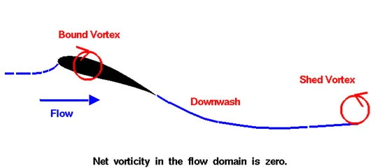
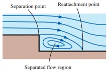
We can also imagine this as ‘Flow separation over a backward facing step along a wall’.
- From 8 to 50 degrees AOA,
Overall drag increases further as AOA increases but lift started decreasing after a certain angle of attack.
In these cases, flow separation takes place because of the reverse/adverse pressure gradient. As the AOA increases, the reverse/adverse pressure gradient becomes too high to stop the flow in boundary layer and eventually pushing it to flow in reverse direction. This is called Boundary layer separation.
As AOA increases further, the point of separation moves forward on the airfoil until it has so disturbed the flow around the airfoil that further increase in AOA produce less rather than more lift. In this condition the wing is said to be stalled.
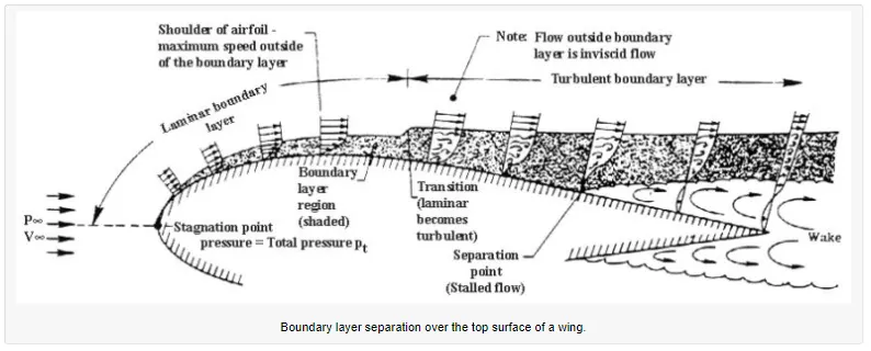
Note:- In above image the AOA is very low hence separation region is near the trailing edge.
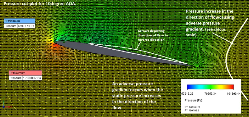
On comparing lift force values, from the data table, at 30degrees and 40degrees, we can say that lift start to decrease, on further increasing the AOA after 30degrees while the drag force steadily keeps on increasing with AOA. Also, we can observe after 40degrees AOA, the drag starts to become significantly larger than the lift. So, we can say that after 30degrees stall starts to occur in our airfoil.
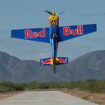
Stall, when occur in an aircraft, dose not necessarily means that it will come crashing down. As long as the generated lift is greater than or equal to the weight of the aircraft and thrust produced by the engines are greater than the drag the aircraft will fly. As we can see from the picture below.
- An important consequence of flow separation is the formation and shedding of circulating fluid structures, called vortices, in the wake region. The periodic generation of these vortices downstream is referred to as vortex shedding.
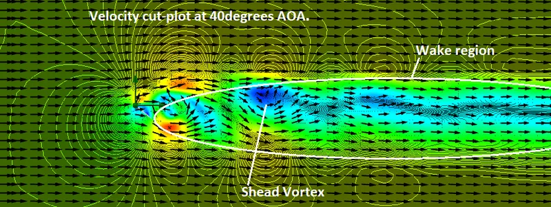
The wake region also becomes larger and wider as the AOA increases.
The region of flow trailing the body where the effects of the body on velocity are felt is called the wake.
References:
FLUID MECHANICS (FUNDAMENTALS AND APPLICATIONS) by Yunus Cengel and John Cimbala.
Harvs Air Services.
https://www.flight-mechanic.com/airfoils/
https://aerospaceengineeringblog.com/boundary-layer-separation-and-pressure-drag/