Flow over an airfoil
AIM:
To model the flow over NACA0017 airfoil and compare the lift and drag force for the angle of attack 0,2,4,6,8,10.
THEORY:
Airfoil is defined as the cross-section of a body(shape of wing, blade of propeller rotor or turbine or sail) that is placed in an airstream in order to generate useful aerodynamic force.
This force can be broken down into two components, lift and drag. The lift produced by an airfoil is the net force produced perpendicular to the relative wind. The drag incurred by an airfoil is the net force produced parallel to the relative wind.
The NACA airfoils are airfoil shapes for aircraft wings developed by the National Advisory Committee for Aeronautics (NACA). The shape of the NACA airfoils is described using a series of digits following the word "NACA".
The NACA four-digit wing sections define the profile by
- First digit describing maximum camber as a percentage of the chord.
- The second digit describing the distance of the maximum camber from the airfoil leading edge in tenths of the chord.
- Last two digits describing the maximum thickness of the airfoil as a percent of the chord.
For example, the NACA 2412 airfoil has a maximum camber of 2% located 40% (0.4 chords) from the leading edge with a maximum thickness of 12% of the chord. The NACA 0017 airfoil is symmetrical, the 00 indicating that it has no camber. The 17 indicates that the airfoil has a 17% thickness to chord length ratio: it is 17% as thick as it is long.
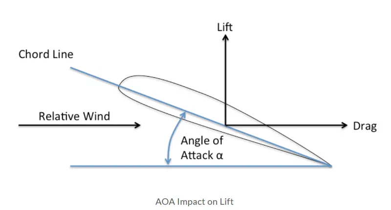
Angle of attack is the angle between the oncoming air or relative wind and a reference line on the airplane or wing. Sometimes, the reference line is a line connecting the leading edge and trailing edge at some average point on the wing.
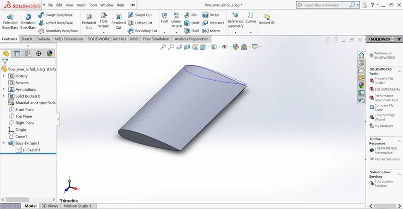
Geometry
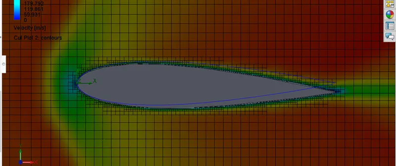
Result of using local mesh feature at level 3(finer mesh near-surface)
RESULT:
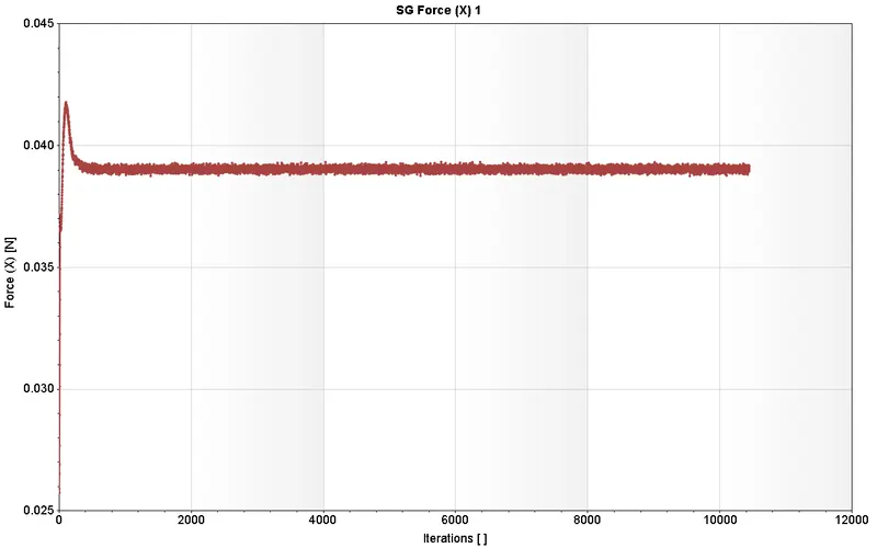
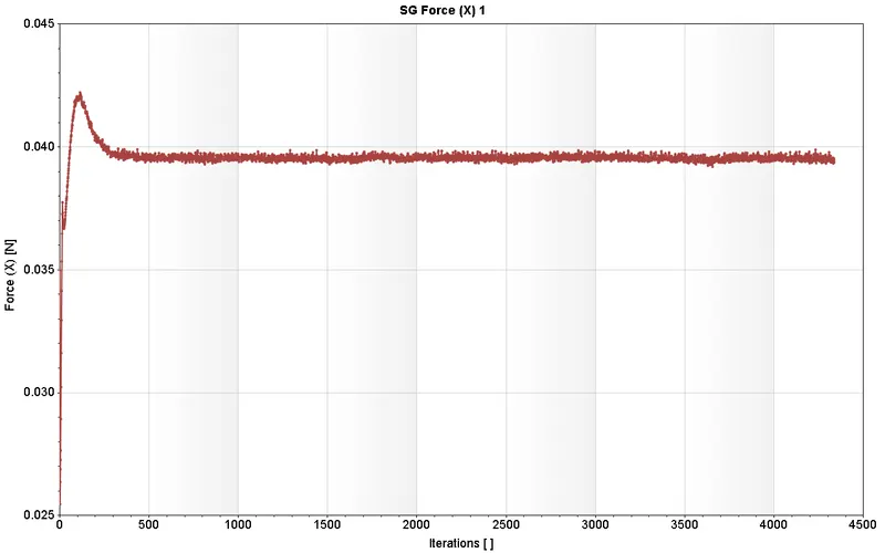
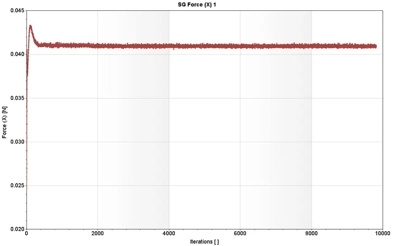
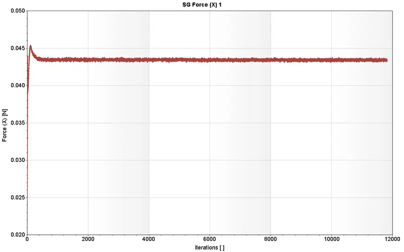
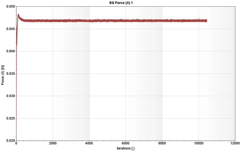
SG Force (X)1 denotes (integrated) Surface Goal force at X-axis which is called Drag Force.
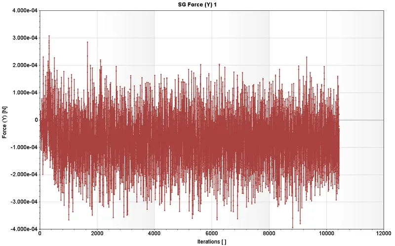
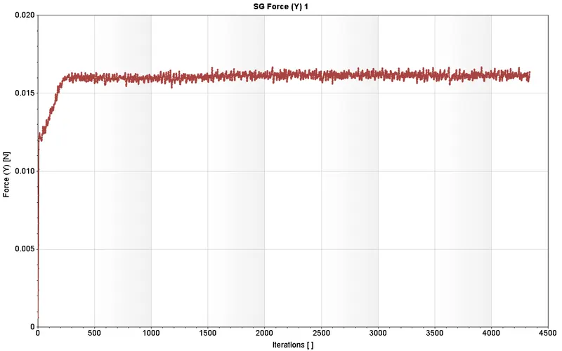
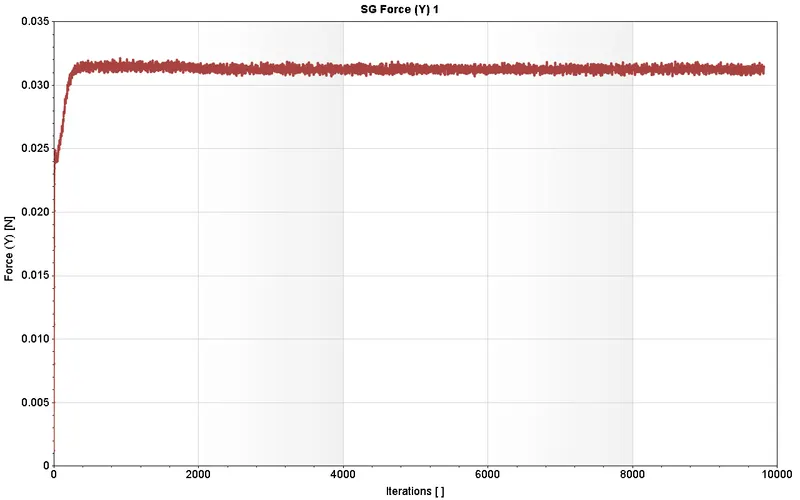
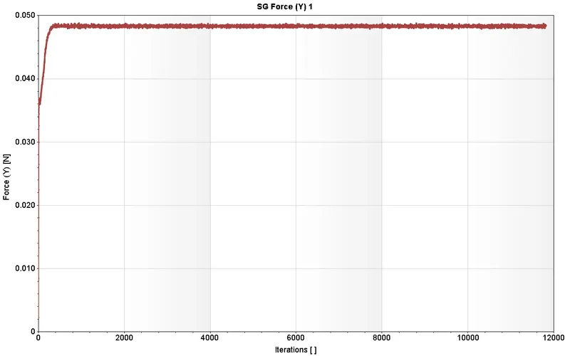
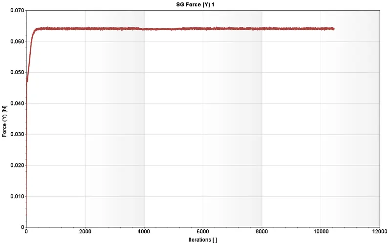
SG Force (Y)1 denotes (integrated) Surface Goal Force at Y-axis which is called Lift Force.
Case 1: (Angle of attack = `0^o` )
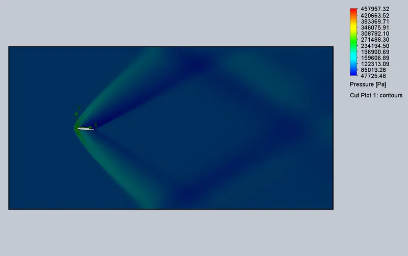
Pressure contour
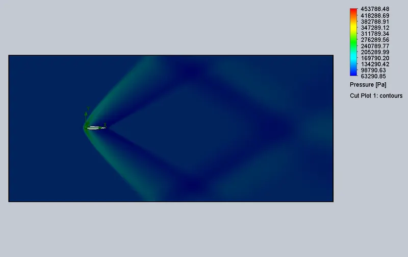
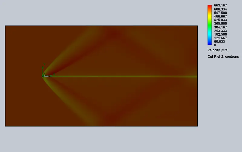
Velocity contour
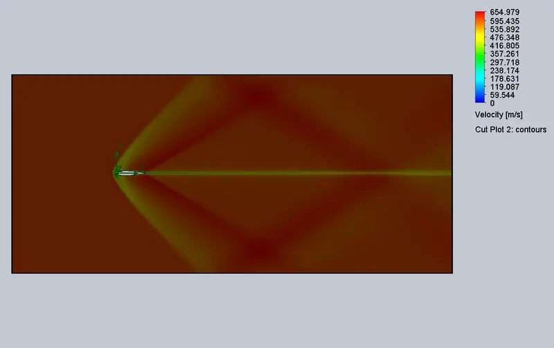

Drag force Lift force
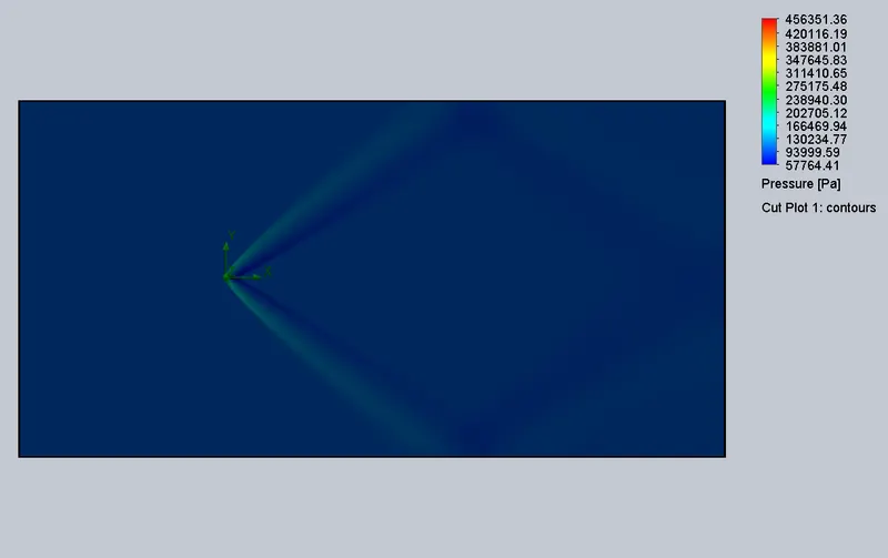
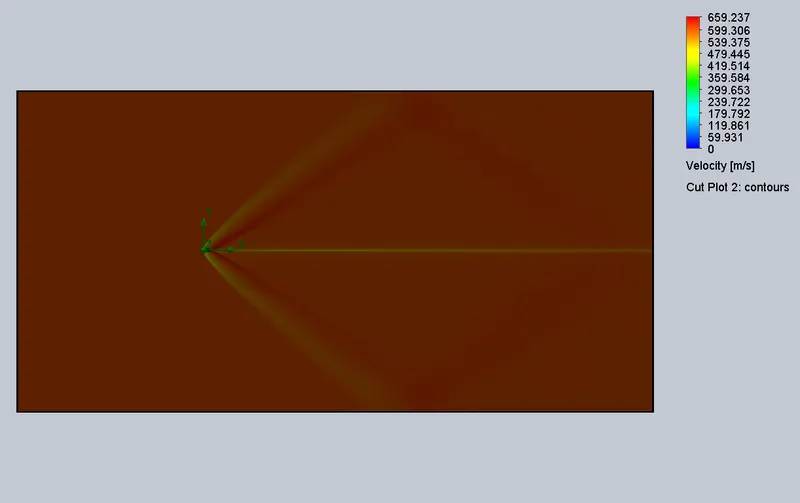
Case 2: (Angle of attack = `2^o` )
Pressure contour
Velocity contour

Drag force Lift force
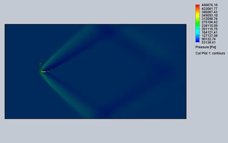
Case 3: (Angle of attack = `4^o` )
Pressure contour
Velocity contour

Drag force Lift force
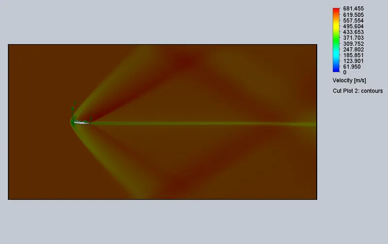
Case 4: (Angle of attack = `6^o` )
Pressure contour
Velocity contour

Drag force Lift force
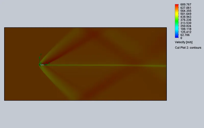
Case 5: (Angle of attack = `8^o` )
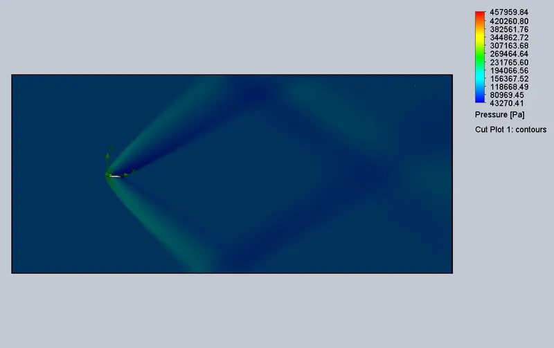
Pressure contour
Velocity contour

Drag force Lift force
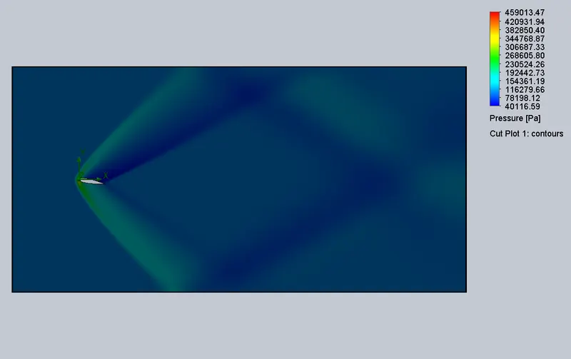
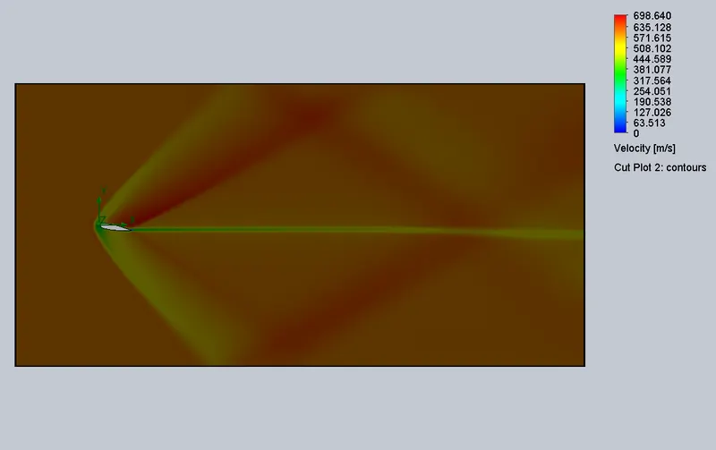
Case 6: (Angle of attack = `10^o` )
Pressure contour
Velocity contour

Drag force Lift force
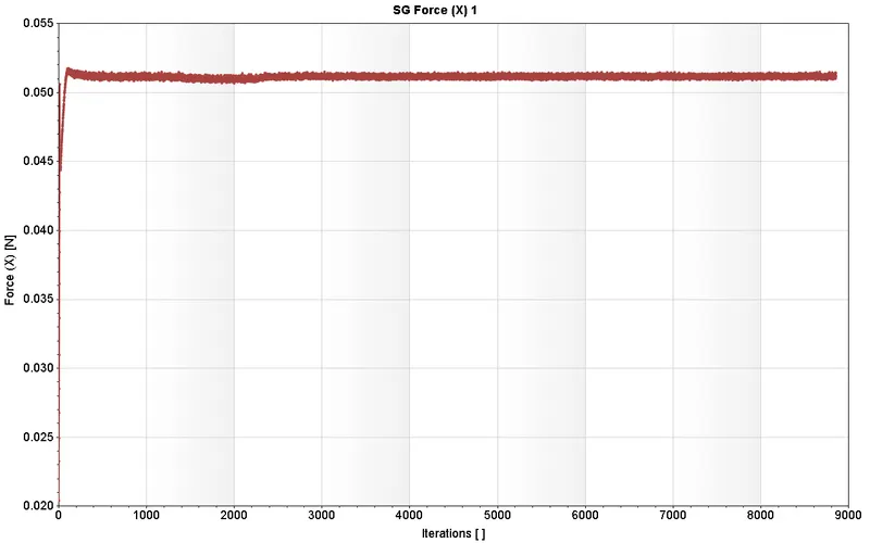
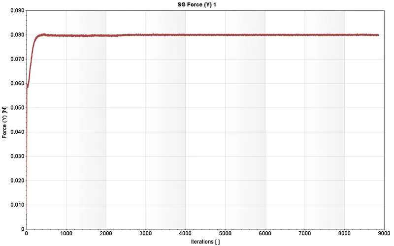
| Angle of Attack (deg) | Avg Drag force (N) | Avg Lift force(N) |
| 0 | 0.03903 | -0.00006 |
| 2 | 0.03949 | 0.01609 |
| 4 | 0.04095 | 0.03129 |
| 6 | 0.04342 | 0.04834 |
| 8 | 0.04685 | 0.06412 |
| 10 | 0.05118 | 0.08003 |
INFERENCE:
- With the increase in the angle of attack, the velocity of air over the airfoil increased.
- The lift force is least in `0^o` angle of attack (from the summary)as the shape is symmetrical and this can be observed in the surface goal plot in the y-direction
- With the increase in the angle of attack, Drag force increases slowly, and Lift force increases rapidly.