FINAL TEST
FINAL TEST
PFI QUESTIONS
Q1. What is the Compression ratio for the engine?
The compression ratio (CR) is defined as the ratio of the volume of the cylinder and its headspace (including the pre-combustion chamber, if present) when the piston is at the bottom of its stroke to the volume of the headspace when the piston is at the top of its travel (‘top dead center’, TDC). Typically, petrol engines have a CR of 8–10, while diesel engines have a CR of 15–20. The CR of petrol engines is limited by the requirement that the fuel burns uniformly in the cylinder and does not ignite thermally prior to the spark (so-called ‘engine knocking’).
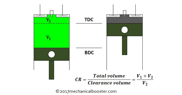
i.e. CR=VBDCVTDCVBDCVTDC=V1+V2V2V1+V2V2
where VBDCVBDC-> Volume of the gas when the cylinder is at the bottommost position.
VTDCVTDC->Volume of the gas when the cylinder is at the topmost position.
BDC->Bottom Dead Centre
TDC->Top Dead Centre
For an internal combustion engine (Diesel Engine), a high compression ratio is favorable because of the higher thermal efficiency of the system. As a result, the internal combustion engine can reach high combustion temperature which provides more work output for the same amount of fuel. This is because the IC engine is conceptually based on the heat engine and as a result, longer expansion cycles provide more work output and less heat wasted to the surroundings in the form of exhaust.
Q2. Modify the compression ratio for this engine to 10.3 without changing geometrical parameters.
The geometrical parameters of an engine are crank rod length, bore, stroke, etc. These parameters are constant for a particular engine. The only way that we can change the compression ratio of this engine to 10.3 is by varying
V1andV2V1andV2, where they are swept volume and clearance volume respectively.
From the PFI engine data, we ge that the maximum and minimum volumes respectively are as follows:
Vmax=5.74∗10−4m3;Vmin=5.7∗10−5m3Vmax=5.74∗10-4m3;Vmin=5.7∗10-5m3
Note that since maximum volume occurs when the piston is at BDC and minimum volume occurs when piston is at TDC, therefore
V2=Vmin;V1=Vmax−V2V2=Vmin;V1=Vmax-V2
⇒V2=5.7∗10−5m3⇒V2=5.7∗10-5m3 and V1=5.17∗10−4m3V1=5.17∗10-4m3
Substituting in the CR equation and evaluating for V2V2, we get
10.3=5.17∗10−4+V2V25.17∗10-4+V2V2
V2=5.56∗10−5m3V2=5.56∗10-5m3
Now following the same procedure and evaluating for V1V1, we get
V1=5.301∗10−4m3V1=5.301∗10-4m3
Q3. Calculate Volumetric Efficiency for this engine
Volumetric efficiency in an internal combustion engine design refers to the efficiency with which the engine can move the Charge of fuel and air into and out of the cylinders. It also denotes the ratio of air volume drawn into the cylinder to the cylinder's swept volume. More specifically, volumetric efficiency is a ratio of the mass of air and fuel that is trapped by the cylinder during induction divided by the mass that would occupy the displaced volume is the air density in the cylinder was equal to the ambient air density.
The volumetric efficiency of an engine is given by,
ηv=Volume of air sucked into the cylinder during intake stroke displacement Volumeηv=Volume of air sucked into the cylinder during intake stroke displacement Volume
ηv=VaVd×100ηv=VaVd×100
Displacement volume was found previously and was equal to 5.17×10⁻⁴m35.17×10-4m3
To find the amount of air sucked into the cylinder during the intake stroke, assuming the air used is ideal in nature.
Now by using the ideal gas equation,
P.Va=m.R.TP.Va=m.R.T
∴Va=m.R.TP∴Va=m.R.TP
where,
P= Pressure of air at atmospheric conditions = 101325Nm−2Nm-2
m = Mass of air
R = Universal gas constant = 287 J/Kg-k
T = temperature of air at atmospheric conditions = 293k
=0.000534kg=0.000534kg
Substituting the values of P,m, R, and T in the ideal gas equation, we get,
Va=4.4317× 10⁻⁴m3Va=4.4317× 10⁻⁴m3
Substituting the value in the Volumetric efficiency equation.
We get,
ηv=4.4317×10−45.17×10−4×100=85.719%ηv=4.4317×10-45.17×10-4×100=85.719%
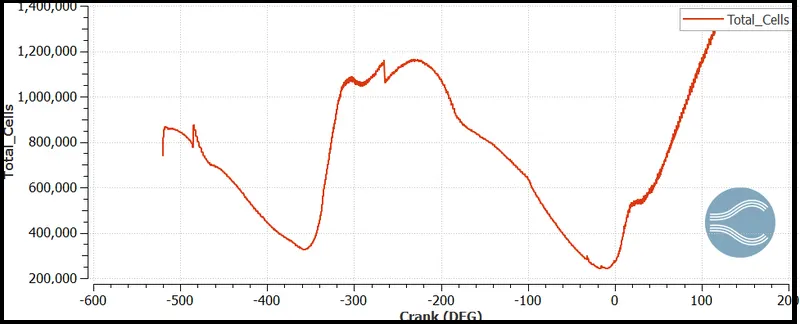
To find the air mass flow rate for the engine we need to know the mass of the air. The mass of the air can be found by the Mass vs Crank plot in the 3rd3rd equation. According to the plot
Mass of the air, m = 0.000534 kg
The mass of the air measured is the mass flow rate of air into the cylinder per one cycle ie, for 360 deg.
The speed of the engine is 3000 RPM. Converting it into RPS,
Speed of the engine in RPS = 300060=50RPS300060=50RPS
Thus, the actual angle covered in one second is 50 x 360 = 18000 deg
To find the mass of air entering the engine at 18000 deg,
we know that,
Mass of air entering at 360 deg = 0.000534 kg
For Mass of air entering at 18000 deg = 0.000534 x 50 = 0.0267 kg/s
Air mass flow rate for this engine = 0.267 kg/s
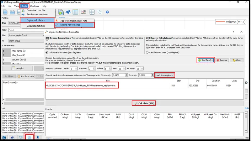
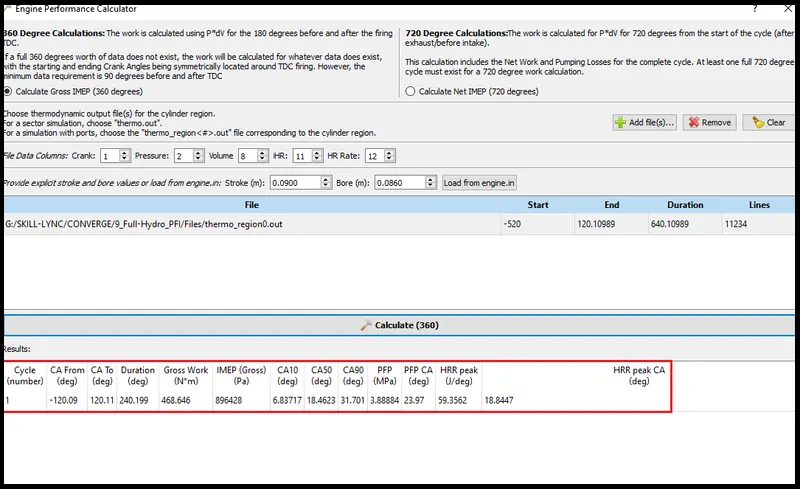
WKT engine rpm-3000
Therefore, rps-50
dps (degrees per second)=360*50=18000
time taken=24018000=0.11331s24018000=0.11331s
DIESEL ENGINE QUESTIONS
Q1. What is an advantage of SECTOR Simulation?
TIME & RESOURCE! Using the sector simulation helps us to save a lot of time in CFD calculations, which reduces the overutilization of computer resources. As discussed, the Diesel engine has an almost symmetric geometry, which can be exploited because math becomes easy once symmetry is found. The results that we get for sector simulation are applicable for the full engine as well. Note that this method is advantageous only in close-cycle systems.
Q2. When will the sector approach not work?
The sector methodical approach will definitely fail when we introduce fuel injection systems, exhaust and intake systems, turbocharger systems, and so on. Moreover, upon introducing these elements, we have to stick with open-cycle analysis rather than close-cycle analysis. If we use sector modeling, we can't simulate the fuel injection process and motion of valves and turbocharger actions which form part and parcel of the bigger picture.
Q3. How to choose Start Crank Angle (SCA) and End Crank Angle (ECA) for a sector simulation?
As we know, the sector simulation is based on the close cycle assumptions, so the analysis is only valid at the beginning of the compression stroke and ends at the completion of the expansion stroke. For instance, if the fuel injection takes place at 0 CAD then the compression stroke starts from 180 CAD and is valid till the end of the expansion stroke at 540 CAD.
Q4. Can we convert the PFI case into a SECTOR case? Explain your answer?
A big NO!
A port fuel injection cannot be converted into a sector model. The sector model is symmetric because we ignore more crucial aspects like fuel injection etc. If we do the same in a PFI engine, then we will get inaccurate mixing and hence, wrong physics! Also, the chief difference between PFI and diesel engines is the presence of a spark plug whereas, in diesel engines, there isn't any. Modeling of spark plug will become a tedious job once we include symmetricity. Also, we have ports that get divided into two near the combustion chamber, so applying symmetry conditions there seems obsolete. Hence in the PFI engine, we cant use the Make engine sector tool.