FINAL TEST
Q1. What is the Compression ratio for the engine?
ANS: The compression ratio is defined as the ratio of the volume of the cylinder and its headspace (Including the pre-combustion chamber, if present) when the piston is at the bottom of its stroke to the volume of the headspace when the piston is at the top of its travel("Top Dead Center"). Typically, petrol engines have a CR of 8-10, while diesel engines have a CR of 12-20. The CR of petrol engines is limited by the requirement that the fuel burns uniformly in the cylinder and does not ignite thermally prior to the spark (so-called 'engine knocking). In a spark-ignition engine, the CR at which pre-ignition takes place is determined by the octane number of the petrol. High octane fuel permits a high CR. Until about 30 years ago, lead tetraethyl was added to petrol as an anti-knock agent. This was phased out for environmental reasons and non-toxic additives are now sometimes used. Improvements in engine design over recent years have, however, led to a satisfactory compression ratio with lower octane fuel.
Effects of Compression Ratio on Engine Combustion: The Compression Ratio, in this case for a realistic engine it is the effective one, has two effects on combustion. The first, and obvious effect, is on the thermodynamic cycle. The pressure and temperature at the end of compression will be affected by the compression ratio, with a higher compression ratio increasing both will also have a significant effect on the geometry of the combustion chamber, and a higher compression ratio will often result in a combustion chamber of narrower aspect ratio. This means that the flame will contact the piston earlier, and this will tend to reduce the rate of heat release. The compression ratio of the base engine was both increased and decreased.
Q2. Modify the compression ratio for this engine to 10.3 without changing geometrical parameters.
ANS:
To achieve a higher compression ratio is possible by changing the clearance volume or displacement volume values.
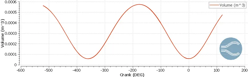
- The below calculations show both method's clearance volume and displacement volume.
`CR= (V_d+V_c)/V_c`
`CR`= static compression ratio
`V_d`= displacement volume
`V_c`= clearance volume
Where
`V_t = V_d+V_c`
`V_t`= sroke volume
CLEARANCE VOLUME
`V_t/V_c=10.3`
`V_t=10.3*V_c`
`V_t=0.000574219`
`0.000574219/10.3=V_c`
`V_c=0.00005574941747572816`
DISPLACEMENT VOLUME
`V_t/V_c=10.3`
`V_t=10.3*V_c`
`V_c=0.0000575439`
`V_t=10.3*0.0000575439`
`V_t=0.00059270217`
Q3. Calculate Volumetric Efficiency for this engine
ANS:
The volumetric efficiency in internal combustion engine engineering is defined as the ratio of the mass density of the air-fuel mixture drawn into the cylinder at atmospheric pressure to the mass density of the same volume of air in the intake manifold.
`eta_v`=`V_a/V_d` Volume of air sucked into the cylinder during intake stroke/Displacement volume
`V_a=(mRT)/P`
m= Mass of Air = 0.000500516(Kg)
R= Universal Gas Constant = 287 J/Kg-K
T=Temperature 293K
P=Pressure = 101325 `m^-2`
`V_a=(mRT)/P``= (0.000500516*287*293)/101325`
`V_a=(mRT)/P``= 4.153850575474957e-4 m^3`
`V_d =`0.00057421
`eta_v`=`V_a/V_d`= `(4.153850575474957e-4)/0.000574219`
`=>` 0.7233913498987245x100
`=>`72.33%
The Volumetric Efficiency of the engine is `eta_v=72.33%
Q4. Measure the air mass flow rate for this engine in kg/s
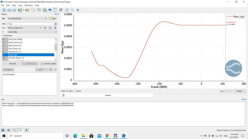
ANS:
To calculate the mass flow rate of air into the engine, we need to know the speed of the engine.
The speed of the engine is 3000 RPM
To convert them from minutes to seconds = 3000/60 =50 RPS.
The angle covered in one second is 360 degrees = 50x360 = 18000 degrees
`:.` From the plottings, the Mass of Air is = 0.000500516 x 50 = 0.267 Kg/s.
Q5.Why is the cell count varying during the simulation?
ANS:
- The cell count changes are dependent on the Adaptive Mesh Refinement(AMR) and Fixed Embedding values we provided while the case setup. In the PFI and Diesel engine simulations, I have provided velocity and temperature AMR's to have accurate values of velocity and temperature gradients near the spark plug and chemical reaction centers during the simulation. I have provided a scale of 3 and subgrid criteria(SGS) to be 1 for the velocity and a scale of 3 and subgrid criteria(SGS) of 2.5 for temperature.
- In numerical analysis, AMR is a method of adapting the accuracy of a solution within certain sensitive turbulent regions of simulation, dynamically and during the time the solution is being calculated.
- When solutions are calculated numerically, they are often limited to pre-determined quantified grids as in the cartesian plane which constitutes the computational grid, or mesh.
- Many problems in numerical analysis, however, do not need a uniform precision in the numerical grids used for plotting or computational simulation and would be better suited if specific areas of graphs need precision. AMR provides such a dynamic programming environment for adapting the precision of the numerical computational based on the requirements of a computation problem in specified locations.
- Subgrid criteria (SGS) is an integral part of AMR. As the AMR is used for different parameters Temperature, Velocity, Pressure, and Species, etc.
- The SGS is provided with a predefined value. If the parameter exceeds the specified value in the SGS, the AMR automatically enables.
- Fixed Embedding is a smart feature. It helps in adding extra mesh in specified locations.
- This offers numerous benefits including the ability to apply more cells near a wall and get an increase in accuracy and running a fast coarse mesh without distorting the geometric representation.
- The following regions and boundaries included in fixed embedding including, Intake valves, Exhaust valves, Cylinder region, nozzles, and sparkplugs.
- The fixed embedding act as an additional refinement in that areas.
- For example in the cylinder region, the energy emitted through the source term resides for a longer period of time and numerical diffusion takes place.
- The fixed embedding is active for a very small duration of time, helps in capturing the better seed values, temperature gradients.
- This also initiates AMR to be activated in that region or a particular area.
Q6 In a real engine, valves are in contact with the cylinder head but while running simulation, there is a small gap. WHY?
ANS:
- In the real engine, the valves are in contact with the cylinder head because to ensure that the heat inside the cylinder is sealed so that the engine does not lose its thermal efficiency and also to dissipate the heat from cylinder walls to the cylinder head.
- In the real engine, valve springs and retainers are used to keep them in contact.
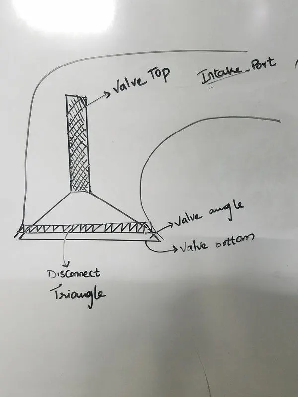
- In the simulation, the valves do not close completely there will be a small gap or minimum lift as shown in the below picture. If these valves are closed or moved backward there might be an intersection error.
- Every valve in this simulation is divided into three boundaries Valve top, angle, and bottom. These boundaries are assigned to different regions. The Valve angle and valve top are assigned to intake_port and the valve bottom is assigned to the cylinder region.
- This helps in identifying the location of the parts and also the temperature and pressure inside the cylinder and intake port are not the same. Multiple regions are created to describe the maximum pressure, temperature, and chemical kinetics involved in it.
- On the other hand, to restrict the flow through these small gaps CONVERGE creates a DISCONNECT TRIANGLE to prevent the air-fuel mixture from entering the combustion chamber with the help of the regions and boundaries.
- The flow cannot enter into the cylinder when these triangles are present or active and the flow can pass through in the absence of these triangles.
- The disconnect triangles are operated using EVENTS.
Qb. What happens if this gap is big?
ANS:
- If the gap between them is big, the heat transfer between the cylinder head and cylinder will not happen.
- This causes a rise in temperature of the cylinder which leads to detonation/pre-ignition/induces knock and also engine might emit more unwanted gases like NOx and soot which will tend to spoil the environment.
- This can also cause the lifer of the engine and its efficiency to decrease by a great margin.
Q7. How many seconds does combustion last in this case?
ANS:
- The engine performance can be calculated using converge software.
- It is found that for combustion stroke the crank angle is running through 240 degrees.
- The engine speed is 3000 rotations per minute or 50 rotations per second.
- It takes one second to complete 18000 degrees.
- Time taken to complete 240 degrees is t=240/18000=0.0133 seconds.
Questions based on DIESEL Engine:
Q1. What is an advantage of SECTOR Simulation?
ANS:
- a close sector surface analysis. In this type of analysis, the inlet ports, exhaust ports, inlet valves, exhaust valves are ignored the simulation performs the calculation on the piston or the combustion chamber as shown in the initial steps and pictures.
- "make engine sector surface" tool develops a part of piston with a specified angle.
- In the toolbox, the sector angle is specified to be 60 degrees that mean the injector has six nozzles inside the combustion chamber (360/60 = 6).
- The benefits of close sector surface are it reduces the computational cost, by eradicating the ports and valves the simulation time decreases, and this also helps in concentrating the characteristic changes inside the combustion chamber.
Q2. When will the sector approach not work?
ANS:
- The close sector simulation is not suitable for open-cycle analysis. In the open cycle analysis, the Valves ie., inlet and exhaust valves position change from time to time and one crank angle to another crank angle
- As the valves are varying according to time, the close sector simulation cannot capture the valves and their effects with respect to time.
- And also the sector simulation cannot be implemented on a multi-injector engine. Because in sector simulation the nozzles are aligned to be symmetric at the center axis of the engine.
Q3. How to choose Start Crank Angle (SCA) and End Crank Angle (ECA) for a sector simulation?
ANS:
- As explained in the above line that the close sector simulation is applicable only for close cycle analysis.
- The starting of the simulation could be taken at the beginning of the compression stroke and the end of the simulation can be taken at the end of the expansion stroke.
- We can consider the fuel injection at 0 CAD or 180 CAD and 540 CAD as End of Crank Angle for diesel engine.
Q4. Can we convert the PFI case into a SECTOR case? Explain your answer?
ANS:
- The port fuel injection cannot be converted into a sector simulation. The sector simulation can simulate only a certain portion of geometry as explained in the previous project.
- The port fuel injector, the nozzle is positioned outside the combustion chamber.
- Whereas, in close sector simulation the nozzle is aligned inside the cylinder and it is symmetrical.
- The PFI needs a sparkplug for combustion and in sector simulation, we cannot model a sparkplug.