Final Project: Design of an Electric Vehicle
AIM :-
To create a MATLAB model of an electric car which uses a battery and a DC motor. The objectives of this project are,
- To design a simple model with a low run time.
- To understand the performance parameters with various parameters.
- To study how various inputs affect the vehicle.
THEORY :-
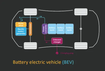
The components in an electric vehicle are,
On-Board Charger: It is an AC-DC power converter or a rectifier that takes the incoming AC current from the power grid and converts it to DC power to charge the battery. Through the Battery Management System (BMS) characteristics such as voltage, current, temparature and state of charge is regulated.
Traction Battery Pack: It is a high voltage battery used to store energy in the electric car and provide power for use by the electric traction motor.
Battery Power Converter: It is a DC-to-DC power electronic converter that converts the voltage of the traction battery pack to the higher-voltage of the DC-bus used for power exchange with the traction motor.
Power Electronic Converter: A power electronic converter is made of high power fast-acting semiconductor devices, which act as high-speed switches. Different switching states alter the input voltage and current through the use of capacitive
and inductive elements. The result is an output voltage and current, which is at a different level to the input.
Motor Drive: It is a DC-to-AC or a DC-to-DC power electronic converter, used to convert power from the high voltage DC bus to AC or DC power for the operation of motor. The converter is bidirectional for operating in both driving and regenerative braking mode.
Electric Motor/Generator: It is the main propulsion device in an electric car that converts electrical energy from the traction battery to mechanical energy for rotating the wheels. It also generates electricity by extracting energy from the rotating wheels while braking, and transferring that energy back to the traction battery pack.
MATLAB MODEL :-
The Simulink model of the electric vehicle is shown below.
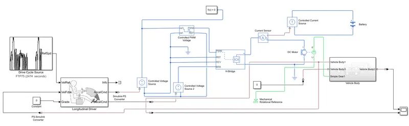
Explanation of the model,
The first thing to be created is the vehicle body. It is a subsystem which consists of the wheels, transmission and the chassis. The model inside the subsystem is shown below.
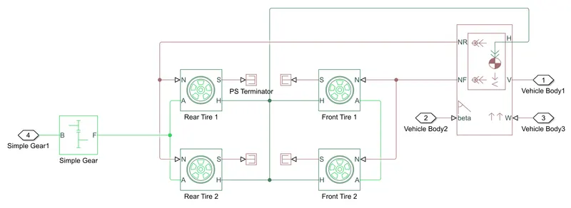
The blocks used are,
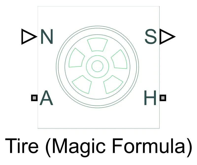
Tire Block: This block represents the longitudinal behavior of a tire of a highway. Connection A is the mechanical rotational port for the wheel axle. Connection H is the mechanical translational port for the wheel hub through which the thrust developed by the tire is applied to the vehicle. Connection N is a physical signal input port that applies the normal force acting on the tire. The force is considered positive if it acts downwards. Connection S is a physical signal output port that reports the tire slip.
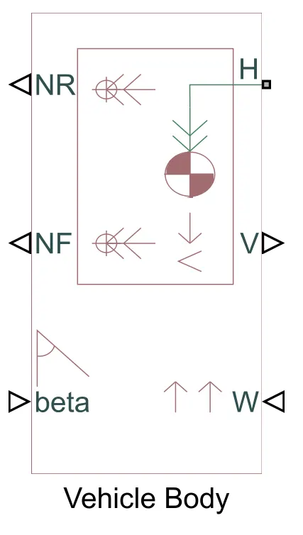
Vehicle Body Block: This block represents a vehicle body in longitudinal motion. The block takes body mass, aerodynamic drag, road incline, and weight distribution between axles due to acceleration and road profile into consideration for calculations. Connection H is the mechanical translational port associated with the horizontal motion of the vehicle body. The resulting traction motion developed by tires should be connected to this port. Connections V, NF, and NR are physical signal output ports for vehicle velocity and front and rear normal wheel forces, respectively. Wheel forces are considered positive if acting downwards. Connections W and beta are physical signal input ports corresponding to headwind speed and road inclination angle, respectively.
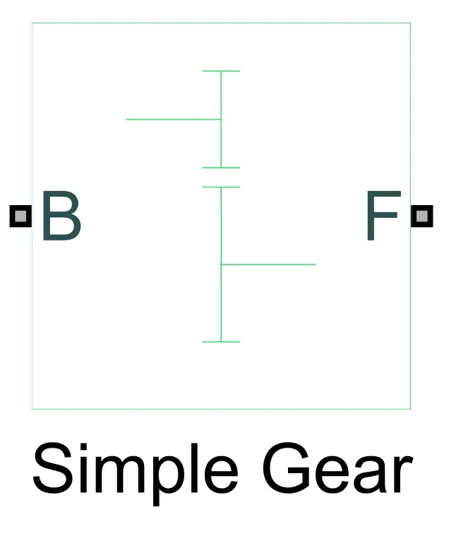
Simple Gear Block: This block represents a fixed-ratio gear or gear box. Connections B (base) and F (follower) are mechanical rotational conserving ports. The base is the input port and the follower is the output port.
Connection order of the subsystem,
- First 4 tire blocks are added and their hub ports (H) are connected to each other. Then the axle ports (A) for the rear tires and front tires are connected to each other.
- The vehicle body block is added to the workspace. Port H of the body block is connected to the tires hub ports (H). The normal rear force (NR) port is connect to the normal force ports (N) of the rear tire and the same is followed for the front tires by connecting the NF port to the N ports.
- The output follower port (F) is connected to the axle ports (A) of the rear tires.
- Since tire slip is not taken into consideration for this model, the slip port (S) is connected to a PS-terminator block.
Once the vehicle body subsystem is created, the electrical section of the vehicle is modeled. The electrical blocks used to create the model are,
DC Motor Block: This block represents the electrical and torque characteristics of a DC motor. The block assumes that no electromagnetic energy is lost, and hence the back-emf and torque constants have the same numerical value when in SI units. Motor parameters can either be specified directly, or derived from no-load speed and stall torque.
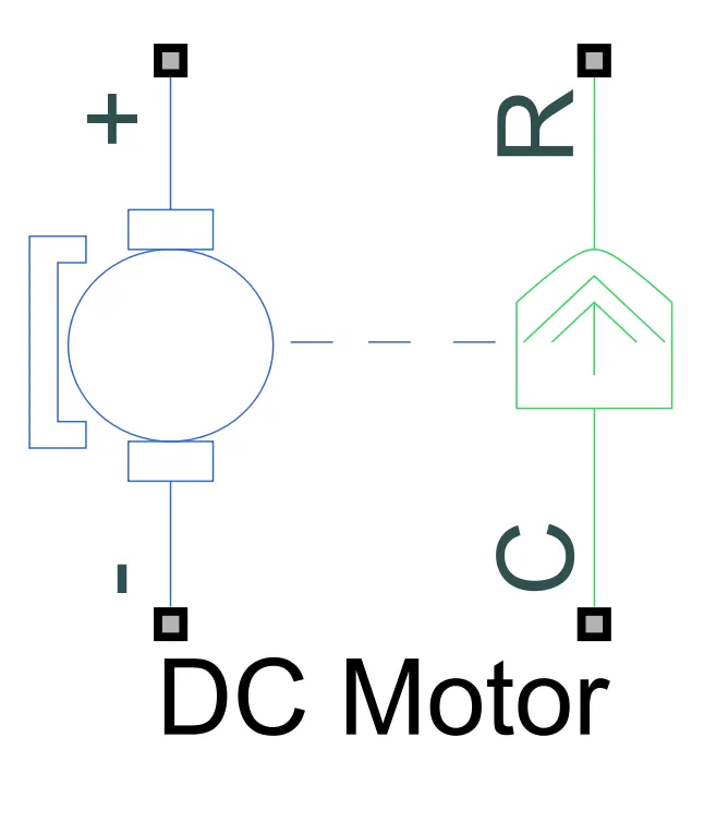
The blue half represents the electrical section and the green half represents the mechanical section. The mechanical ports are the motor case (port C) to which the mechanical reference or ground block is connected and the motor rotor (port R) which is the output shaft of the motor. The port R is connected to the input port of the gear block from the vehicle body subsystem.
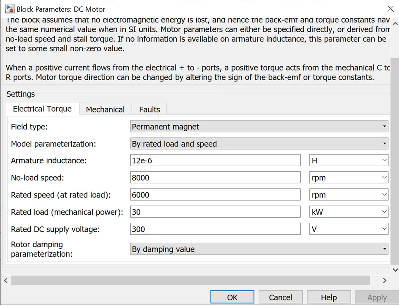
For the simulation the rated load and speed parameterization option is selected where the no-load speed, rated speed, rated load and DC supply voltage are set. The rated power must be changed from V (default) to kW.
H-Bridge block: This block represents an H-bridge motor driver. The block has the following two simulation mode options, PWM (Phase Width Modulation) where the H-Bridge block output is a controlled voltage that depends on the input signal at the PWM port and Averaged which consists of two load current characteristics being smoothed and unsmooth or discontinuous.
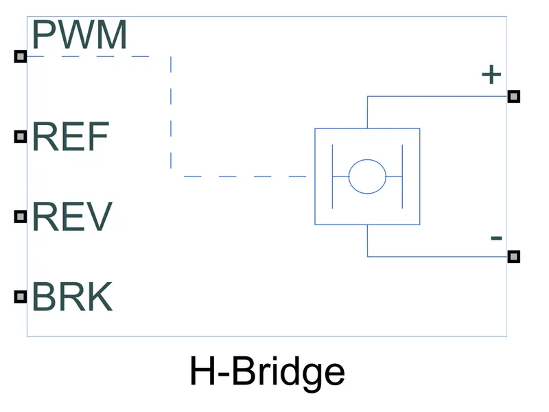
The first port (PWM) is the input port, the second port (REF) is to connect the electrical reference block. The third port (REV) controls the reverse polarity of the block and the fourth port (BRK) controls the short circuit of the block.
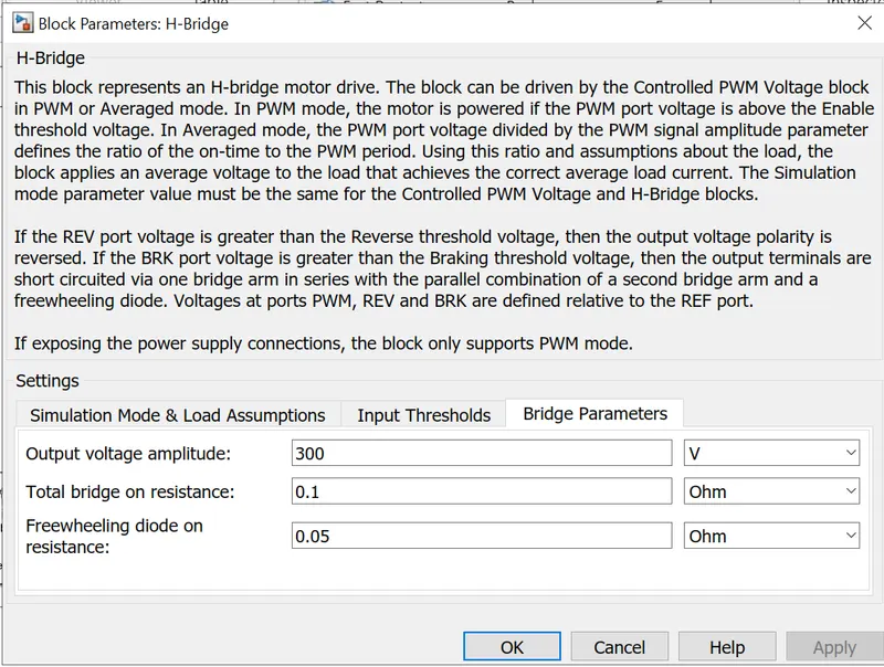
For the simulation, the averaged mode is taken into consideration, the regenerative braking parameter is enabled and the smoothed load current characteristics is defined.
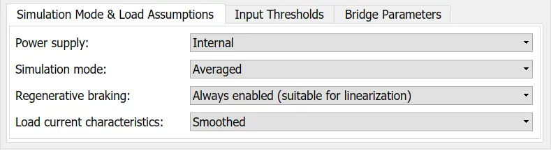
The Output voltage for the simulation is kept at a constant 300 V throughout. The positive and negative ports are connected to the positive and negative ports of the electrical section of the DC motor.
Controlled PWM Block: This block creates a Pulse-Width Modulated (PWM) voltage across the PWM and REF ports. The output voltage is zero when the pulse is low, and is equal to the Output voltage amplitude parameter when high. Duty cycle is set by the input value.
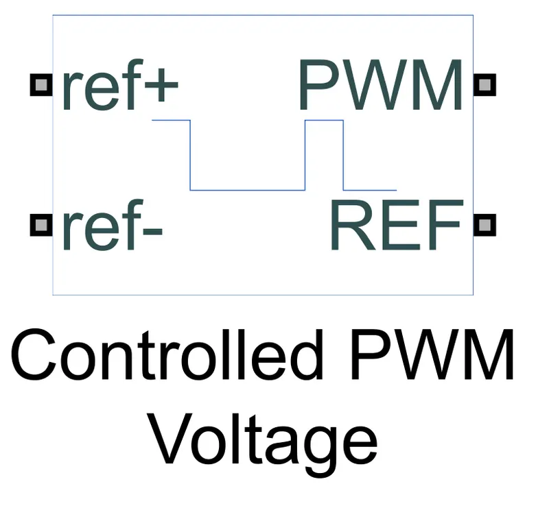
The PWM and REF ports are connected to the ports of the same in the H-bridge block.
Controlled Voltage Source Block: The block represents an ideal voltage source that is powerful enough to maintain the specified voltage at its output regardless of the current passing through it. The output voltage is V = Vs, where Vs is the numerical value presented at the physical signal port.
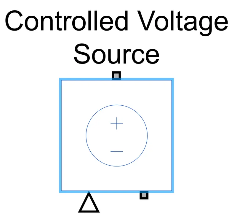
Two voltage source blocks are used for the simulation. One to control acceleration which is connected to the ref+ port of the PWM block and the second for regenerative braking which is connected to the BRK port of the H-bridge block.
Battery Block: This block represents a battery.
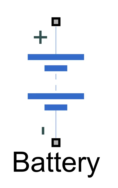
The nominal voltage of the battery is set to 300 V.
Controlled Current Source Block: The block represents an ideal current source that is powerful enough to maintain the specified current through it regardless of the voltage across it. The output current is I = Is, where Is is the numerical value presented at the physical signal port.
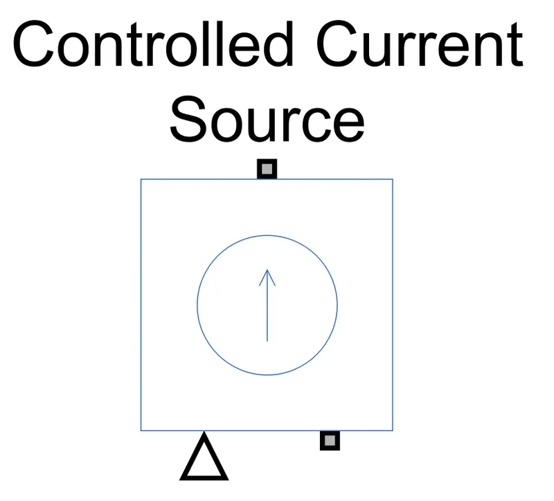
The block is connected to the positive and negative terminals of the battery.
Current Sensor Block: The block represents an ideal current sensor, that is, a device that converts current measured in any electrical branch into a physical signal proportional to the current. Connections + and - are conserving electrical ports through which the sensor is inserted into the circuit. Connection I is a physical signal port that outputs current value.
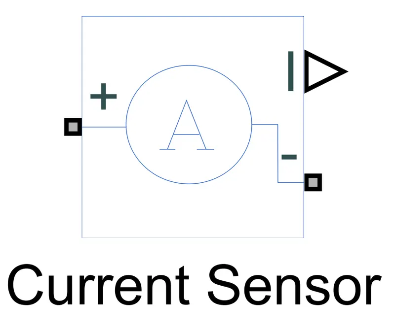
The terminals of the current sensor are connected between the H bridge block and the DC motor.
Once the electrical blocks are modelled, fom the powertrain blockset add-on two blocks are used. One for the input and the second for the vehicle's parameters and they are,
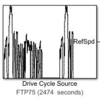
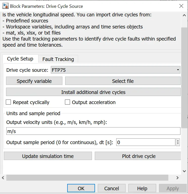
Drive Cycle Source Block: This block is used for the input which represents a drive cycle. The drive cycle used for this simulation is the FTP75 which stands for Federal Test Procedure. This drive cycle is set as default.
Longitudinal Driver Block: It is a block that is used as a controller for driver based inputs which are acceleration and braking.
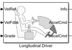
The output port (RefSpd) of the drive cycle block is connected to the VelRef port which calculates the input parameters. The VelFdbk port is connected to the velocity port (V) of the vehicle body block from the subsytem and also the scope in order to plot the input data. The Grade port is set to 0 by using a constant block. The AccelCmd and DecelCmd ports which are the outputs for acceleration and braking respectively are connected to the respective controlled voltage source blocks responsible for acceleration and regenerative braking.
The scope is used to plot the speed of the electric vehicle which compares the actual drive cycle to the input drive cycle. The plot is shown below.
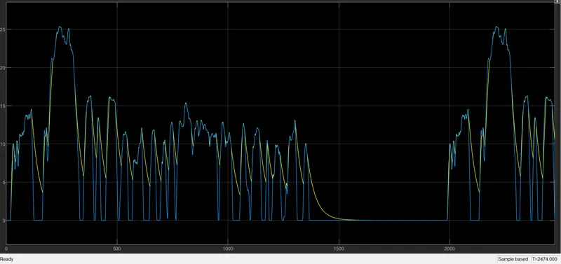
The simulation is run for 2474 seconds which is the standard time of the FTP75 drive cycle. The blue line represents the input speed and the yellow line represents the output or actual speed. It can be observed that the vehicle follows the same pattern of acceleration and coasting as the input drive cycle which can be noted from the overlapping lines. The gradual curves of the yellow line which do not overlap with the input indicates the regenerative braking of the electric vehicle in effect.
CONCLUSION :-
Using Simulink a MATLAB model of an electric vehicle has been created with the blocks used explained and the impact of the driving cycle on the vehicle's speed is analysed.