Week - 4
AIM :-
- To simulate the control logic of a washing machine using stateflow.
- To simulate the gear shift of a transmission based on the speed of the vehicle using stateflow.
SIMULINK MODELS :-
1. Control Logic of a Washing Machine.
The conditions given to run the washing machine are,
- Activate the system if power supply is available.
- If there is no supply stop the process.
- Soaking time should be 200s.
- Washing time should be 100s.
- Rinsing time for 20s.
- Drying time for 50s.
In order to develop the control logic we use stateflow to create a flow chart.
First a chart block is created in the simulink window which is represented as,
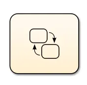
The chart block is double clicked on to open the stateflow window. Once we enter the stateflow window, the flow chart is built.
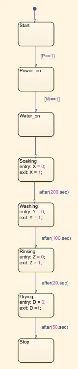
First a block call Start is created, this is to start the process. Then a block titled Power_on is created. This is to provide the condition that if the power supply is turned on [P==1] then the process starts, if not the process does not start. Then a block titled Water_on is created to define the condition of the water supply [W==1]. Once these two conditions are satisfied the washing process begins.
The Soaking block is defined to initiate the soaking process once the power and water supply are on. After 200s the Washing block is activated. Once the washing process is completed the Rinsing block is activated after 100s. The drying block starts when the rinsing completes after 20s. Once the drying runs for 50s the washing process stops.
The symbols pane configuration is used to define the input and output data of the flow chart.
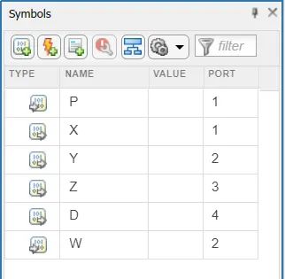
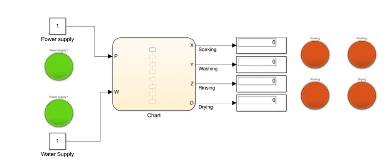
Once the data is defined, the chart block looks like this,
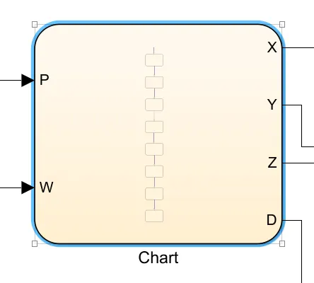
Where the inputs are P and W which are power and water supply. And X, Y, Z and D are the process states being soaking, washing, rinsing and drying respectively.
The simulink model of the washing machine is given below,
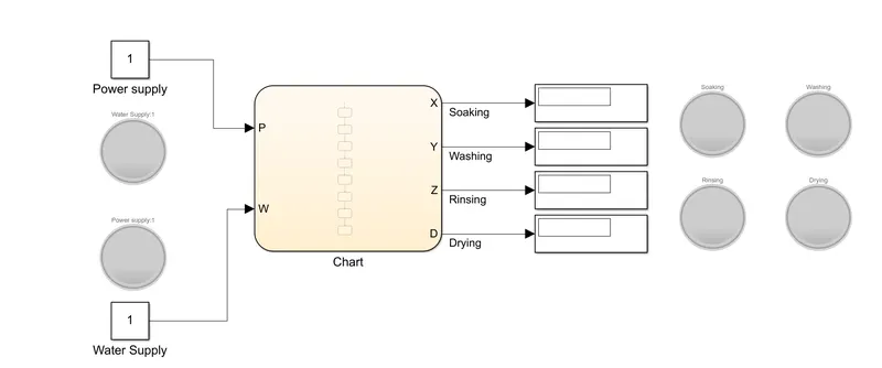
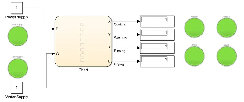
Constant blocks are used to provide the input conditons to the stateflow chart. Display blocks are used to show the process conditions. Lamp is used to highlight the condition of the input and output.
2. Control Logic of a Transmission.
In this section a control logic of a transmission to shift gears is created. The required conditions are,
Speed Range (Km/hr) Gear
0 to 15 1
16 to 25 2
26 to 40 3
41 to 60 4
Above 60 5
The stateflow chart of the transmission is given below.
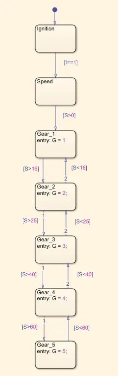
The ignition and speed blocks are the input blocks. The simulation runs only if the ingition is in state 1 or ON. If the speed is greater than 0 then the Gear_1 block engages the first gear. The speed conditions are provided for the stateflow to shift the gear as required. For example if the input speed is greater than 25 Km/hr then 3rd gear is selected but if the speed is less than 25 Km/hr then the 2nd gear is selected.
The simulink model of the transmission is given below,
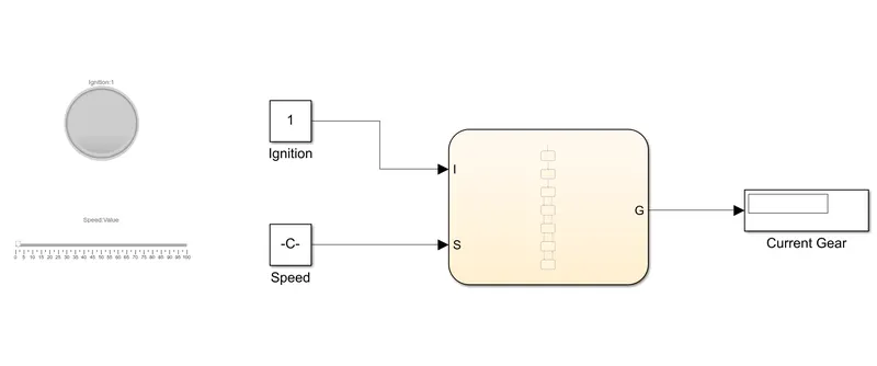
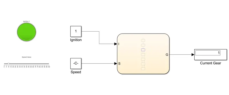
A constant block is used for the ingition to change the state to On and Off (1 and 0). For the speed a slider block is used to continously vary the input to for the stateflow chart block to shift the gears. This slider block is connected to a constant block.
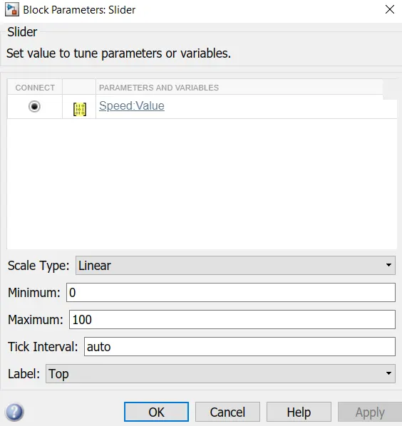
Here the initial speed is set to zero and the maximum speed is set to 100. The run time for this simulation is set to infinity because we can vary the speeds continously using the slider block when the simulation is running and be in the specific gear that we want. The current gear is displayed using a display block.
RESULTS :-
1. Washing Machine.
When the power and water supply is turned on, it is shown as green by the lamp and the washing machine cycle starts.
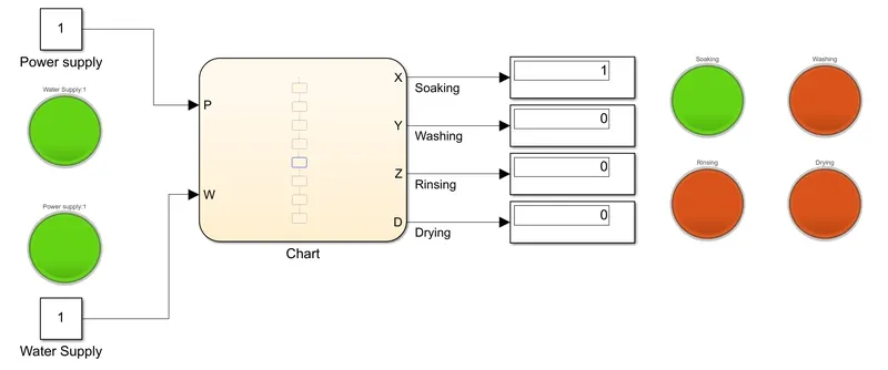
Once the Soaking process is complete, the first lamp turns green. The washing process then starts.
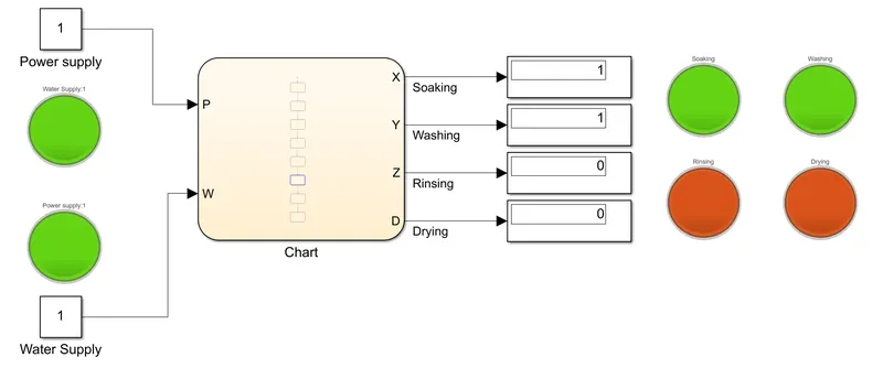
Once the washing process is complete, the second lamp turns green. Then the rinsing process starts.
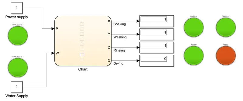
Once the rinsing process is complete, the third lamp turns green. The the drying process starts.
Once the drying process is complete, the fourth lamp turns on and finally the entire operation of the washing machine is completed.
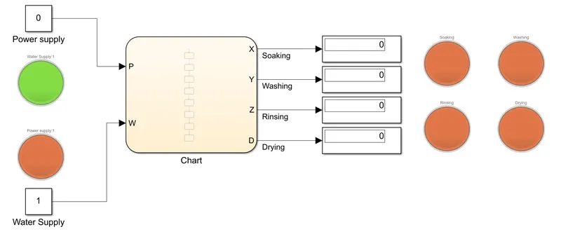
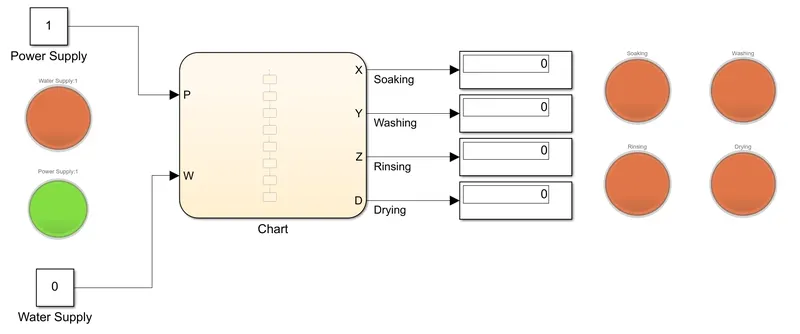
If either the power or the water supply is off then their respective lamps would turn red and the washing machine's operation does not take place.
2. Transmission.
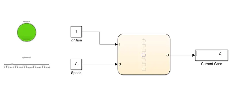
When the ingition is on the lamp turns green. When the speed exceeds 0 the first gear engages. It can be observed that when the speed is at 5 Km/hr, the vehicle is in first gear.
When the speed exceeds 15 Km/hr, the second gear gets engaged.
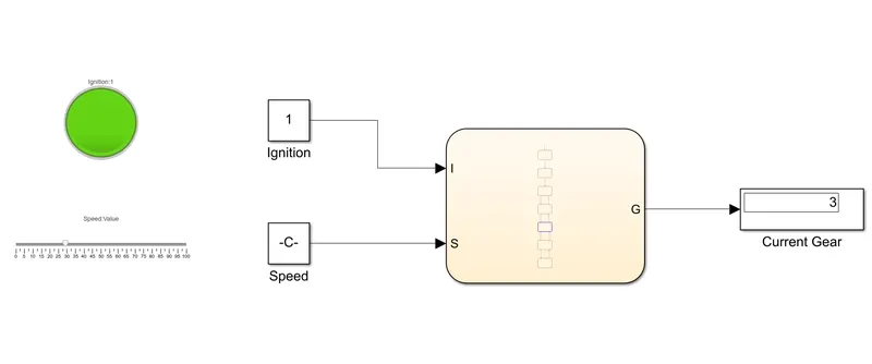
When the speed exceeds 25 Km/hr, the third gear gets engaged.
When the speed exceeds 40 Km/hr, the fourth gear gets engaged.

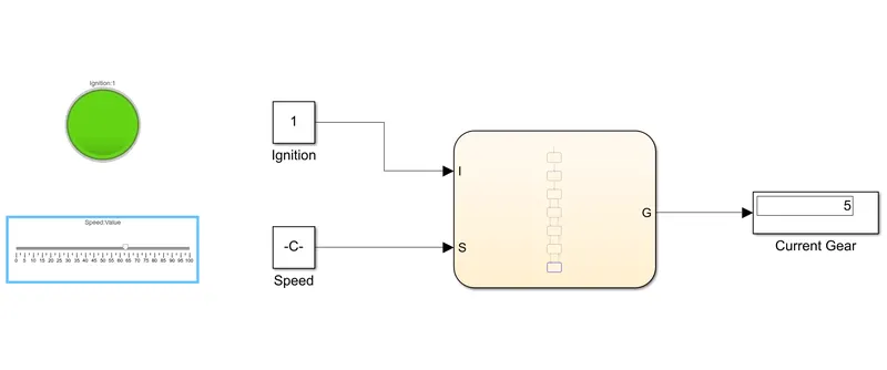
When the speed exceeds 60 Km/hr, the fifth gear gets engaged.
CONCLUSION :-
- Using stateflow we were able to develop a control logic for the operation of a washing machine.
- Using stateflow we were able to develop a control logic for the shifting of gears in a transmission.