Week -2
AIM :-
- To make a Simulink model of a door bell.
- To make a Simulink model of a thermistor to sense the heater temperature for controlling the fan.
THEORY :-
How does a door bell work?
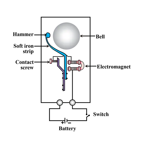
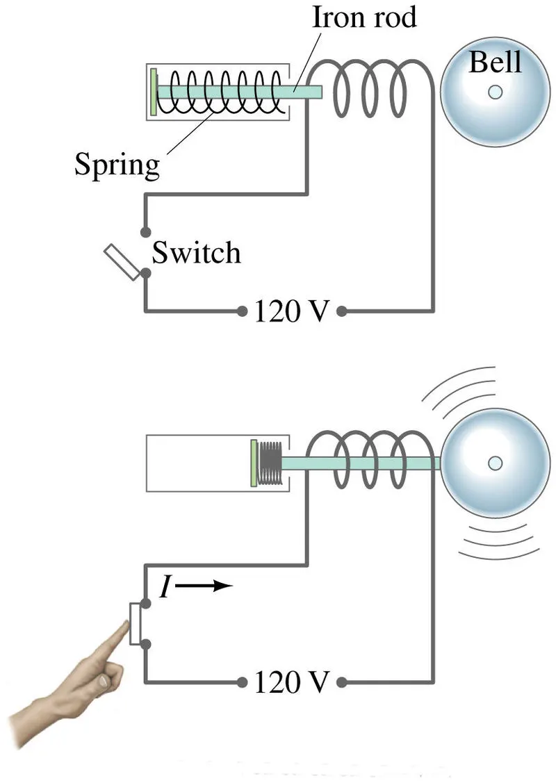
The solenoid piston consists of an iron core mounted to a non-magnetic metal bar. When there is no power to the electromagnet, a spring pushes the piston to the left, and the iron core extends outside of the wire coil. When you turn the electromagnet on (by pressing the doorbell switch), the iron core is drawn to the magnetic field, so it slides into the center of the coiled wire.
As the iron core slides to the right, the end of the piston strikes the right-hand tone bar. The tone bar vibrates, producing a particular note. This is the "ding" sound.
As long the doorbell switch is held, current will flow through the electromagnet and the piston will remain in this position. But when you release the switch, the current will stop flowing through the electromagnet and the magnetic field will collapse. The spring snaps the piston back to the left, where it hits the tone bar on the other side. The second tone bar produces the "dong" sound.
What is a thermistor?
Thermistors are a type of semiconductor, meaning they have greater resistance than conducting materials, but lower resistance than insulating materials. The relationship between a thermistor’s temperature and its resistance is highly dependent upon the materials from which it’s composed.
Thermistors, derived from the term thermaIly sensitive resistors, are a very accurate and cost- effective sensor for measuring temperature. Available in 2 types, NTC (negative temperature coefficient) and PTC (positive temperature coefficient), it is the NTC thermistor that is commonly used to measure temperature.
NTC Thermistor: NTC stands for “Negative Temperature Coefficient. NTC thermistors are resistors with a negative temperature coefficient, which means that the resistance decreases with increasing temperature. They are primarily used as resistive temperature sensors and current-limiting devices.
PTC Thermistor: PTC stands for Positive Temperature Coefficient. PTC thermistors are resistors with a positive temperature coefficient, which means that the resistance increases with increasing temperature.
SIMULINK MODELS :-
1. Model of an electric doorbell:
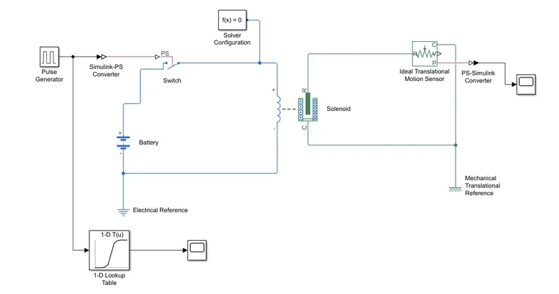
Explanation,
The first block used is the solenoid block. The block consists of an electrical and mechanical component. The electrical component is the coil that is wound around the piston which is highlighted in green.
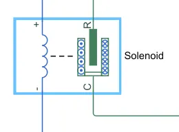
For the electrical section of the door bell, it consists of a battery, switch and an electrical refernce.
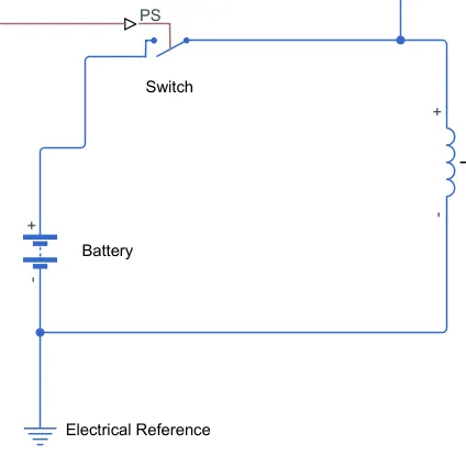
Here, the positive terminal of the battery is connected to one terminal of the switch, and the other terminal of the switch is connected to the positive terminal of the solenoid coil. The negative terminal of the battery is connected to the negative terminal of the solenoid coil and the electrical reference which is nothing but the electrical grounding.
The mechanical section of the door consits of a translational motion sensor and a mechanical translational reference.
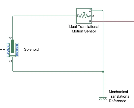
The translational motion sensor is used to determine the postion of the hammer when the solenoid moves it. The rod or plunger denoted as R is connected to the positive probe of the motion sensor with the same denotation and the case of the solenoid denoted as C is connected to the negative probe of the motion sensor with the same denotation. V and P are the physical signals of the sensor represented as velocity and position respectively. In scope block is connected to the P port to obtain the position plot.
The mechanical translational refernce block represents a frame or a ground. It is used to connect mechanical ports that are rigidly fixed, in this case the conserving port associated with the case C of the mechanical system.
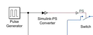
Once the required mechanical and electrical connections are made for the solenoid, we need to now create a source and a scope to provide the input variables and to plot the graph of the hammer. To provide the input variable we use a pulse generator. It used to generate inputs at regular intervals to turn the switch on and off. In order to view the input signal it is connected to a scope with plots the pulse waves.
The input of the pulse generator is converted into a physical signal using the Simulink-PS block.
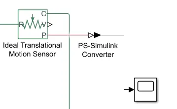
Similarly in order to obtain the position of the hammer, we use a scope block which is connected to the physical signal port P. In order to read the physical signal, a PS-Simulink converter block is used to connect the port P and the scope.
2. Model of a fan controlled by a thermistor:
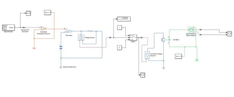
Explanation,
First the signal builder is used to create the input ranges for the model.
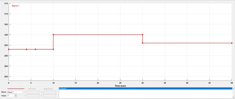
Here the input conditions are,
For 10s the temperature is at 20°C (293 K).
From 10s to 30s temperature is at 27°C (300 K).
From 30s to 50s the temperature is at 23°C (296 K).
Once the input signal is built, the builder is connected to a controlled temperature source which maintains a controlled temperature difference regardless of the heat flow rate.
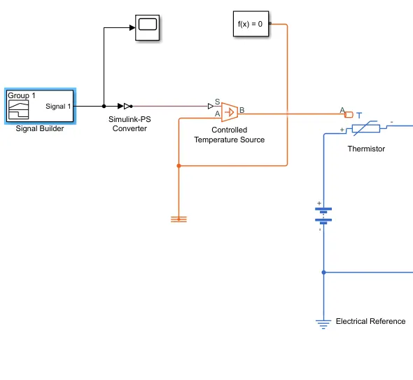
The difference in temperature is set by the physical signal source S and a positive temperature difference causes temperature at port B to be greater than temperature at port A. A solver configuration is connected to the temperature port A which is also connected to the thermal reference. Here the thermal reference in the network is the point at which the temeperature is equal to absolute zero.
The port B is connected to the thermal port A of the thermistor.
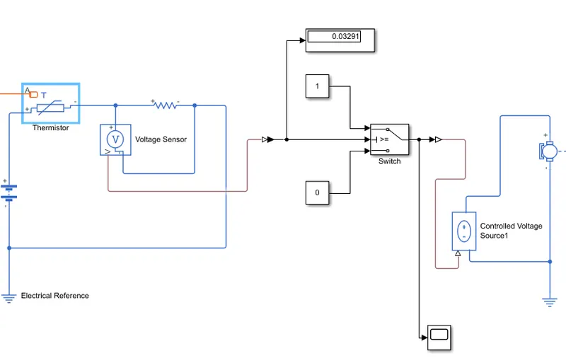
A battery is connected to the positive terminal of the thermistor and the negative terminal of the battery is connected to the electrical reference. The negative terminal of the thermistor is connected to the positive terminal of the resistor and the negative terminal of the resistor is connected to the negative terminal of the battery. A voltage sensor is used to detect the change in voltage that is created by the thermistor. The thermistor used is a Negative Temperature Co-efficient (NTC) type where when the temperature increases, the resistance decreases. This affects the voltage of the circuit.
The voltage sensor is connected to a switch which is used to turn on the fan when the when the temperature reaches 25°C. The output of the switch is connect to a controlled voltage source block which represents the ideal voltage which is powerful enough to maintain the specified voltage as it's output regardless of the current passing through it. The controlled voltage source is then connected to the DC motor.
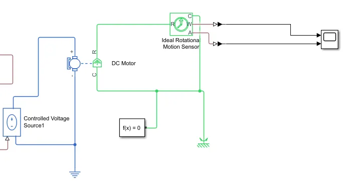
The electrical section of the DC motor is connected to the controlled voltage source. The mechanical section of the DC motor is connected to the rotational motion sensor which is in turn connected to a scope block to obtain the angular displacement (A) and angular velocity (W).
RESULTS :-
1. Electric doorbell:
The simulation is run where the switch is closed for 2 seconds and then opens. The pulse signal of the switch status is given below,
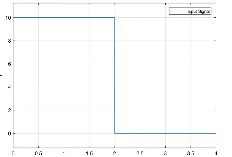
Here we can see that when the input singal is provided the switch gets closed. when the amplitude drops to 0, the switch then enters into the open state.
The plot for the position of the hammer is given below,
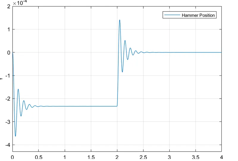
From the graph, we can observe that when the switch is close, the coils get magnetised and moves the rod which in turns brings the hammer in contact with the bell. After 2 seconds, when the switch is in open state the coil gets de-magnetised and the rod returns to it's original positions, resulting in the hammer to move away from the bell.
2. Themistor controlled fan:
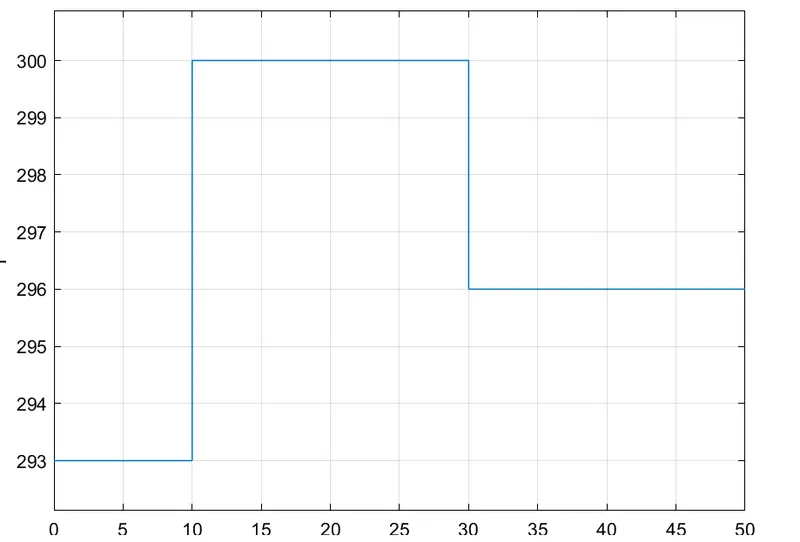
The first graph shows the input ranges of the system.
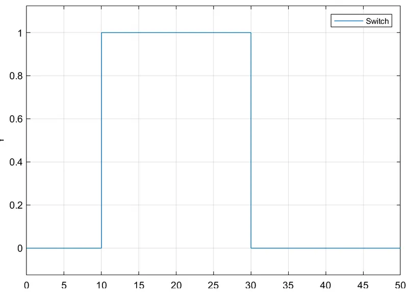
The second graph shows the postion of the switch. When the temperature of the system reaches the range between 10°C to 30°C, the switch turns on which then runs the fan.
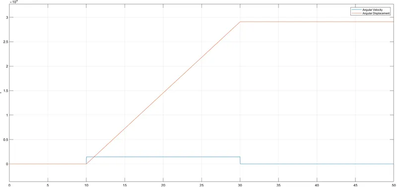
The third graph shows the angular velocity and angular displacement of the fan for the different time steps.
CONCLUSION :-
- We were able to create a model for an electric door bell and plot a graph to understand the postion of the hammer during the operation of the door bell.
- We were able to create a model of a fan that is controlled by a thermistor and control it's operation based on the temperature ranges during a particular duration.