Final Project: Design of an Electric Vehicle
AIM:To create an electric vehicle model using MATLAB / SIMULINK
OBJECTIVES:
1. System level configurations
2. Model parameters
3. Results
4. Conclusion
What is an electric Vehicle?
An electric vehicle (EV) is one that operates on an electric motor, instead of an internal-combustion engine that generates power by burning a mix of fuel and gases. Therefore, such as vehicle is seen as a possible replacement for current-generation automobile, in order to address the issue of rising pollution, global warming, depleting natural resources, etc. Though the concept of electric vehicles has been around for a long time, it has drawn a considerable amount of interest in the past decade amid a rising carbon footprint and other environmental impacts of fuel-based vehicles.
Types of Electric vehicles
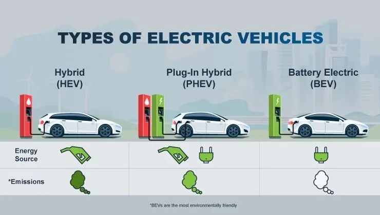
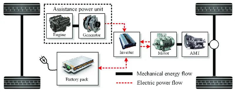
HYBRID ELECTRIC VEHICLE
A hybrid electric vehicle (HEV) is a type of hybrid vehicle that combines a conventional internal combustion engine(ICE) system with an electric propulsion system (hybrid electric drivetrain). The presence of the electric powertrain is intended to achieve either better fuel economy than a conventional vehicle or better performance. There is a variety of HEV types and the degree to which each function as an electric vehicle (EV) also varies. The most common form of HEV is the hybrid electric car, although hybrid electric trucks (pickups and tractors), buses, boats and aircraft also exist.
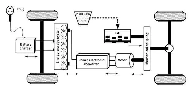
PLUG IN HYBRID VEHICLE
A plug-in hybrid electric vehicle (PHEV) is a type of hybrid electric vehicle that combines a gasoline or diesel engine with an electric motor and a large battery that can be recharged by plugging into an electrical outlet or electric vehicle charging station. Conventional hybrid automobiles have an electric motor and battery, but derive all their power from gasoline or diesel.
Plug-in hybrids typically can run in at least two modes: "all-electric," in which the motor and battery provide all the car's energy; and "hybrid," in which both electricity and gasoline are employed. Some PHEVs can travel more than 70 miles on electricity alone.
BATTERY ELECTRIC VEHICLE
Battery Electric Vehicles, also called BEVs and more frequently called EVs, are fully electric vehicles with rechargeable batteries and no gasoline engine. All energy to run the vehicle comes from the battery pack which is recharged from the grid. BEVs are zero emissions vehicles, as they do not generate any harmful tailpipe emissions or air pollution hazards caused by traditional gasoline-powered vehicles.
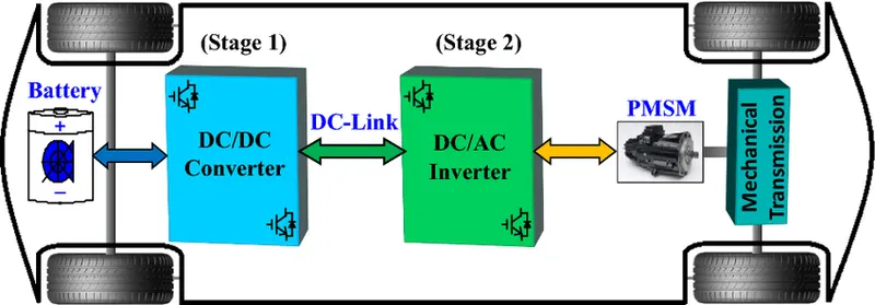
Basic block model of ev
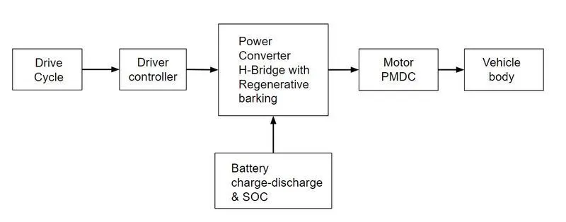
Drive cycle: A drive cycle is typically represented by a series of data points which plots vehicle speed against time. Driving cycles are produced to assess the performance of vehicles in various ways, including fuel consumption and pollutant emissions.
Driver controller: The electric vehicle controller is the electronics package that operates between the batteries and the motor to control the electric vehicle's speed and acceleration much like a carburetor does in a gasoline-powered vehicle.
Power converter with regenerative braking:They are used to process and control the flow of electrical energy by supplying required voltages and current in a form that is optimally suited for the user loads.
Battery: This the powerhouse which supplies the energy required to drive the vehicle.
Motor:It is the rotating device which converts the electrical energy in the form of current and voltage into the mechanical energy at the vehicle through a transmission system.
Vehicle body:This is where the output is achieved via the motor power is transferred to the wheel considering the different forces and resistance and compare with the input drive cycle.
Electric vehicle model
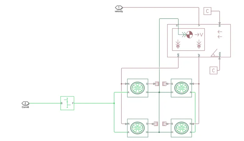
Vehicle Body system
Tire ( magic frame)
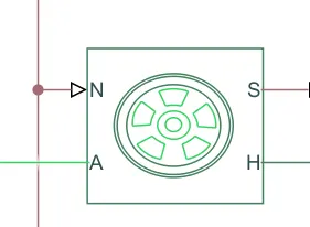
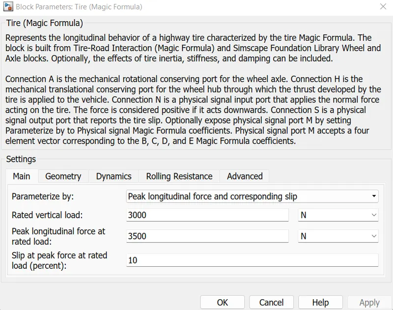
The Tire-Road Interaction (Magic Formula) block models the interaction between the tire tread and road pavement. The longitudinal force arising from this interaction is given by the magic formula, an empirical equation based on four fitting coefficients. Tire properties such as compliance and inertia are ignored.
The A ports of the tire are the mechanical rotational conserving port and receive mechanical rotational input from the gearbox which receives its input from the DC motor.
The H port of the tire is the mechanical translational conserving port for the wheel hub and is connected to the H port of the vehicle body through which the trust developed by the tire is applied to the vehicle.
Here we are not considering any slip, so an terminator block is connected to all the slip port of each tire. Also, grade angle and wind velocity are not considered.
The input is received from the DC motor to the simple gear block which is then transmitted to the wheel considering the inertia couple at the output shaft.
Simple Gear
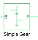
This example shows a simple gear coupling two inertias (shafts). The gear ratio between the follower (F) and base (B) is 2:1. Thus the angular velocity of the follower shaft is half the angular velocity of the base shaft. The follower shaft torque is twice the base shaft torque.
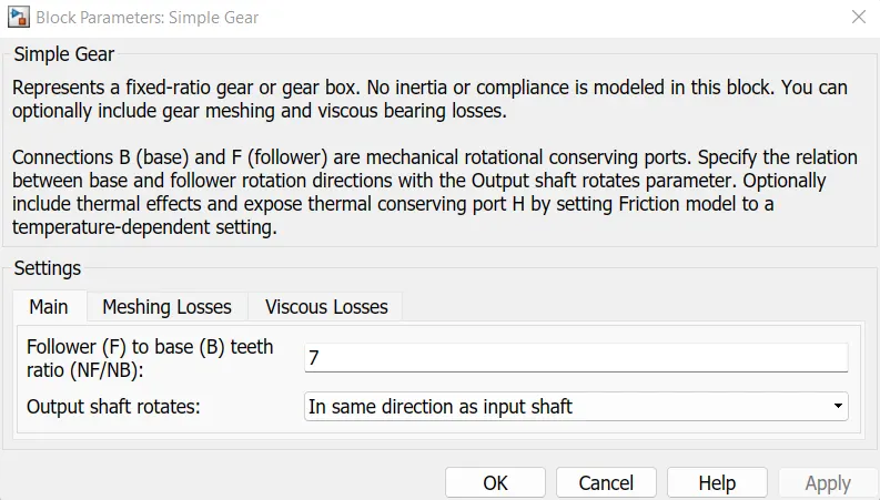
Here we kept a gear ratio of 7 more the gear ratio give better speed with better traction power. beacuse torque is directly is directly proportional to the speed. The gear ratio is high at the start of the vehicle as it requires more torque and as the speed increases,
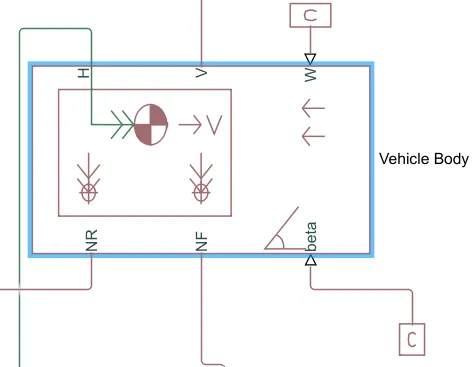
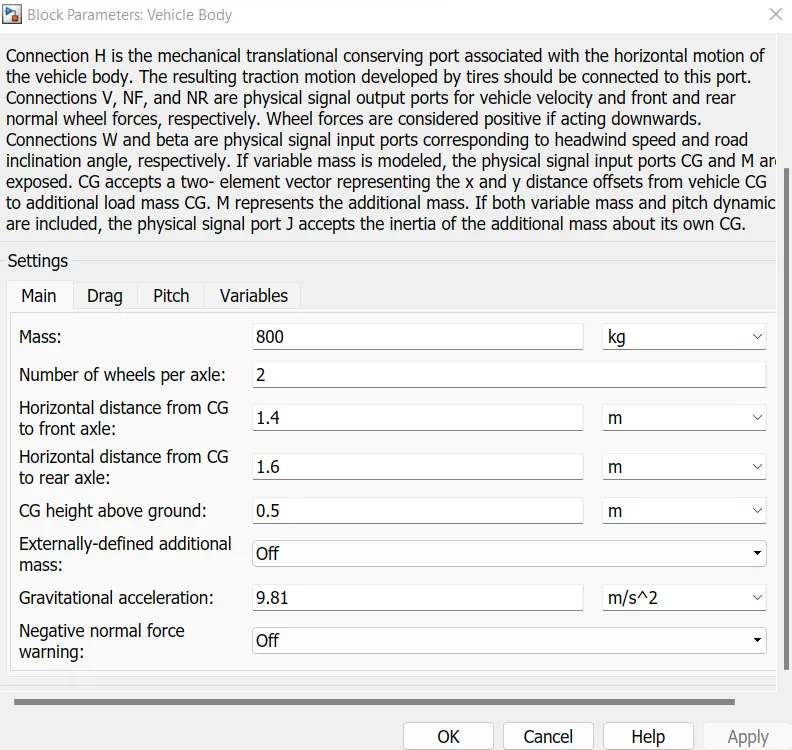
The Vehicle Body block represents a two-axle vehicle body in longitudinal motion. The vehicle can have the same or a different number of wheels on each axle. For example, two wheels on the front axle and one wheel on the rear axle. The vehicle wheels are assumed identical in size. The vehicle can also have a center of gravity (CG) that is at or below the plane of travel.
The block accounts for body mass, aerodynamic drag, road incline, and weight distribution between axles due to acceleration and road profile. Optionally include pitch and suspension dynamics. The vehicle does not move vertically relative to the ground.
The block has an option to include an externally-defined mass and an externally-defined inertia. The mass, inertia, and center of gravity of the vehicle body can vary over the course of simulation in response to system changes.
H- t is the mechanical translation converting port associated with the horizontal motion of the vehicle body
NR- Signal output port for rear normal wheel forces
NF- Signal output port for front normal wheel forces
V- Signal output port for vehicle velocity
Beta- Signal output port for road inclination angle
W- Signal output port for headwind speed
SOC AND BATTERY SYSTEM
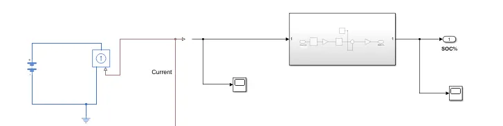
SOC
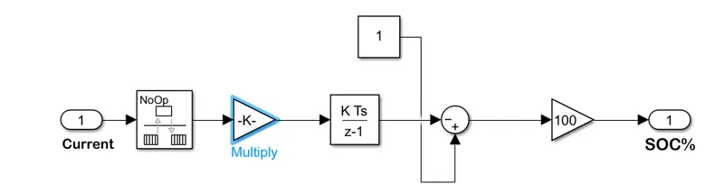
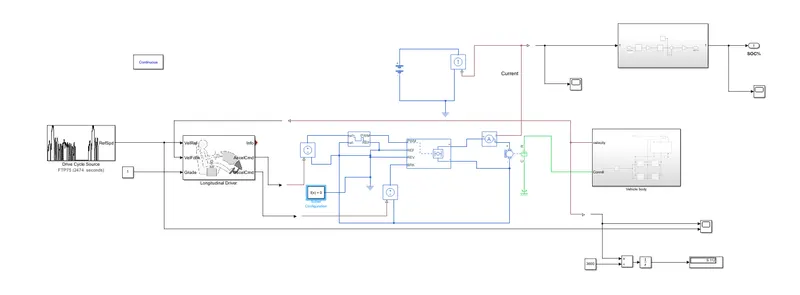
his will determine the voltage level in the battery at each point of simulation. The output from the current block is received at the input signal of the block and display the characteristic of the battery voltage consumed for the particular drive cycle. The sub-block of the SOC contains the Rate transition block, gain block and the discrete time ingegrator. The decrease & increase of the battery voltage is have multiple data point which is handle by the rate transistor. Then this converts these data points and calculate the SOC at each point of the drive cycle. The gain block will calculate the values and display on the scope.
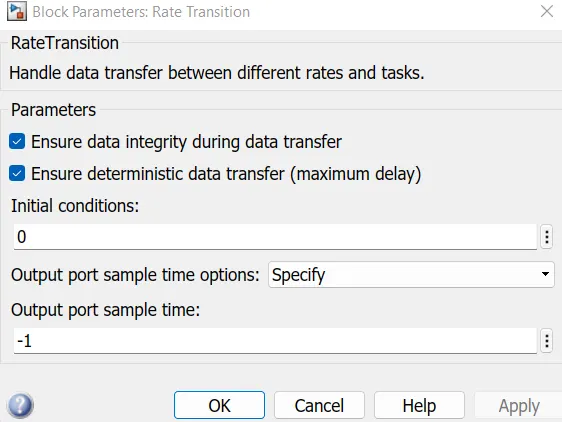
Rate transition
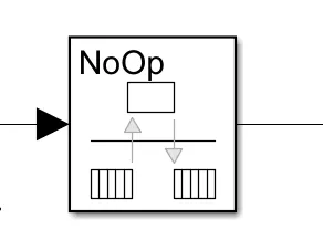
It handles data transfer between different rates and tasks.
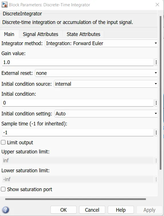
Discrete time integrator
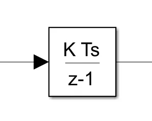
It is the accumulation of the input signals.
BATTERY
This block models a battery. If you select Infinite for the Battery charge capacity parameter, the block models the battery as a series internal resistance and a constant voltage source. If you select Finite for the Battery charge capacity parameter, the block models the battery as a series internal resistance plus a charge-dependent voltage source defined by.
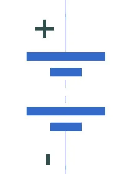
The Battery block represents a simple battery model. The block has four modeling variants, accessible by right-clicking the block in your block diagram and then selecting the appropriate option from the context menu, under Simscape > Block choices:
-
Uninstrumented | No thermal port — A basic model that does not output battery charge level or simulates thermal effects. This modeling variant is the default.
-
Uninstrumented | Show thermal port — Model with exposed thermal port. This model does not measure the internal charge level of the battery.
-
Instrumented | No thermal port — Model with an exposed charge output port. This model does not simulate thermal effects.
-
Instrumented | Show thermal port — Model that lets you measure the internal charge level of the battery and simulate thermal effects. Both the thermal port and the charge output port are exposed.
Controlled current source:
The block represents an ideal current source that is powerful enough to maintain the specified current through it regardless of the voltage across it. The output current is I = Is, where Is is the numerical value presented at the physical signal port.
Power converter
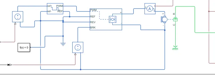
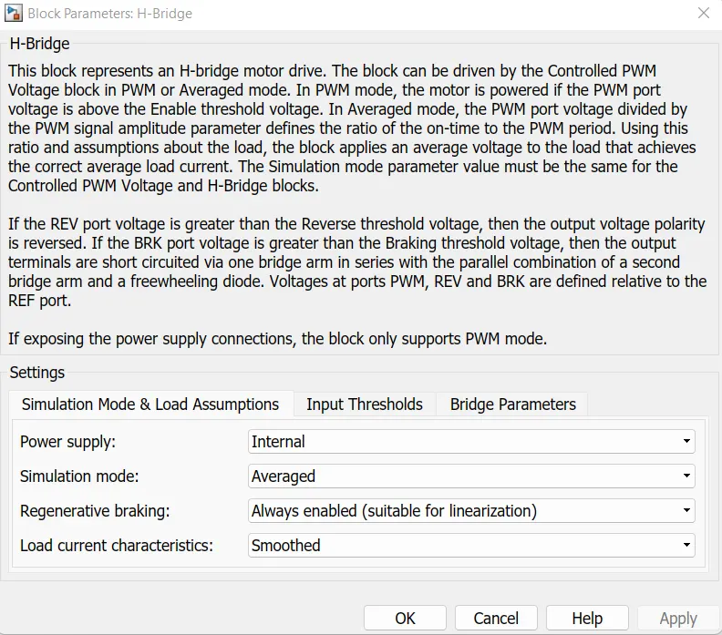
There are two control voltage source one voltage source takes the inpute signal from accelerator or accelerator command from longitudinal driver output and other for braking or deceleration from deceleration command from longitudinal driver. It followed by a controller and a h bridge circuit. The controlled PWM voltage block receives the input signal from the Acceleration's Controlled voltages source and generated modulated width pulses output for the H-Bridge and which is connected to the positive terminal of the block.The PWM signals are received by the H-Bridge connected to the PWM port of it. The other controlled voltage source is connected to the braking port of an H-Bridge. The reverse port is connected to the ground along with the Reference port. Here we have used selected as Average as the simulation mode to reduce the time for the overall operation.a DC motor receives the input signal from the H-Bridge and in between them is the current sensor. The rotational motion signal is sent as an output to the motor shaft. A mechanical rotation reference is connected at the constant port.A battery is attached separately, which is not directly connected to the DC motor but is used for visualization of the SOC of the battery. The signal from the current sensor goes into the controlled current source block. Thus, generating current whenever the vehicle goes into regenerative mode. A subsystem is attached to display the SOC of the battery which is in series with the output signal of the current sensor. Electrical reference acts as a ground and is connected whenever a ground source is required.
DC MOTOR
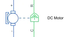
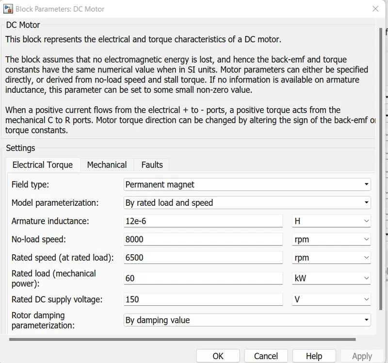
This block represents the electrical and torque characteristics of a DC motor. It assumes that no electromagnetic energy is lost, and hence the back-emf and torque constants have the same numerical value when in SI units. Motor parameters can either be specified directly, or derived from no-load speed and stall torque. If no information is available on armature inductance, this parameter can be set to some small non-zero value.
When a positive current flows from the electrical + to - ports, a positive torque acts from the mechanical C to R ports. Motor torque direction can be changed by altering the sign of the back-emf or torque constants.
PWM
H BRIDGE
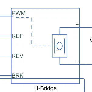
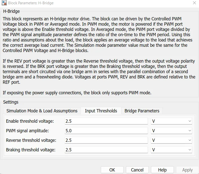
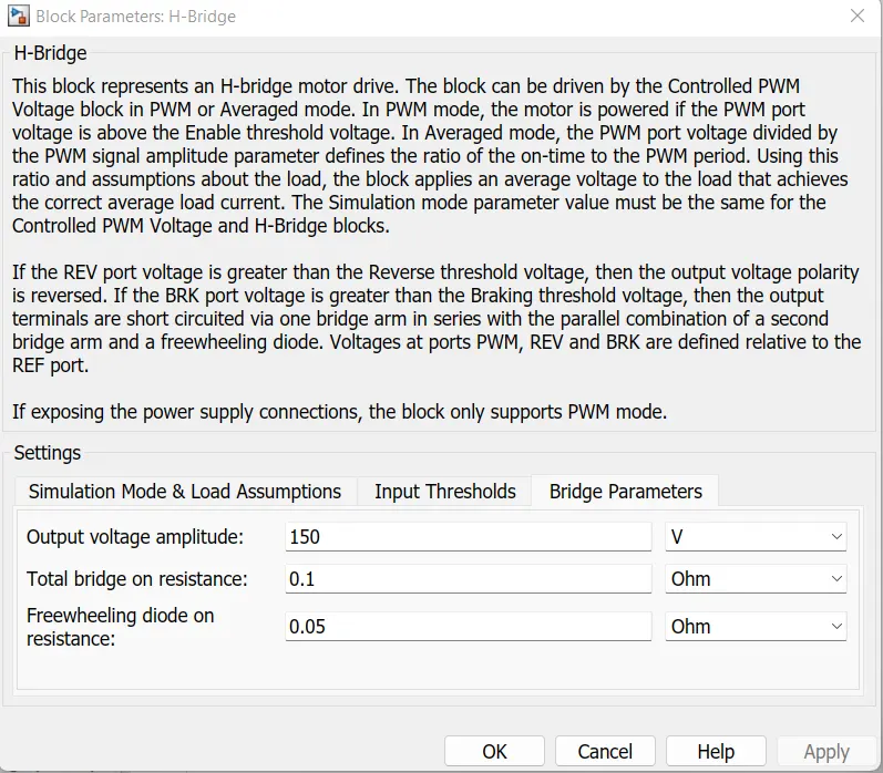
The H-Bridge block output is a controlled voltage that depends on the input signal at the PWM port. If the input signal has a value greater than the Enable threshold voltage parameter value, the H-Bridge block output is on and has a value equal to the value of the Output voltage amplitude parameter. If it has a value less than the Enable threshold voltage parameter value, the block maintains the load circuit using one of the following three Freewheeling mode options:
- Via one semiconductor switch and one freewheeling diode
- Via two freewheeling diodes
- Via two semiconductor switch and one freewheeling diode
Simulation mode and load assumptions
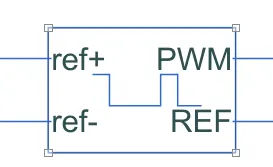
Controlled PWM Source
This block creates a Pulse-Width Modulated (PWM) voltage across the PWM and REF ports. The output voltage is zero when the pulse is low, and is equal to the Output voltage amplitude parameter when high. Duty cycle is set by the input value.
The Simulation mode can be set to PWM or Averaged. In PWM mode, the output is a PWM signal. In Averaged mode, the output is constant with value equal to the averaged PWM signal.
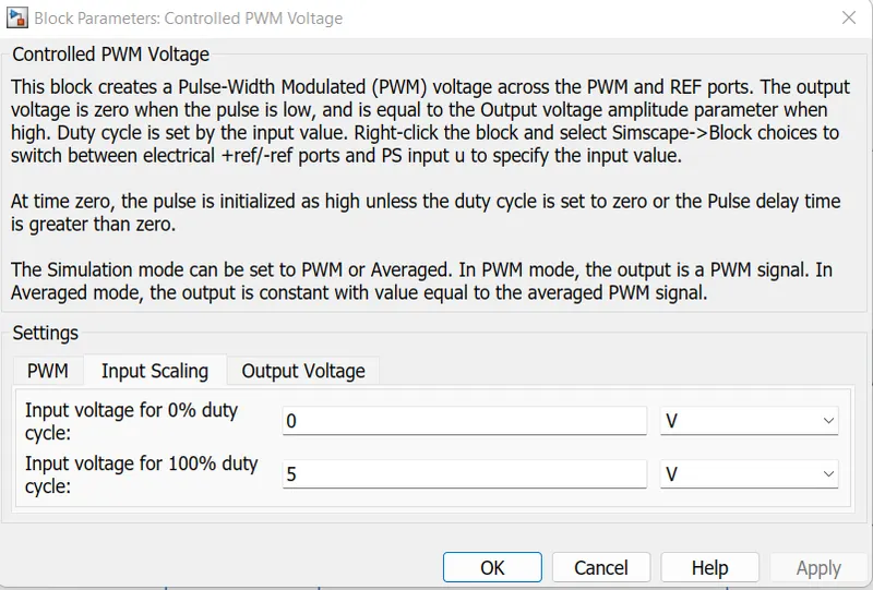
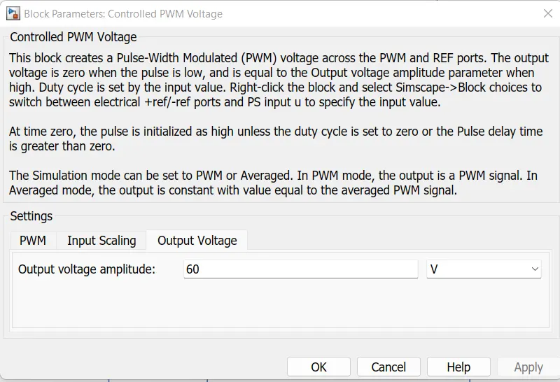
Parameters
PWM frequency is set to 1000 Hz and the simulation mode is set to average because it also set as same in an H-bridge. 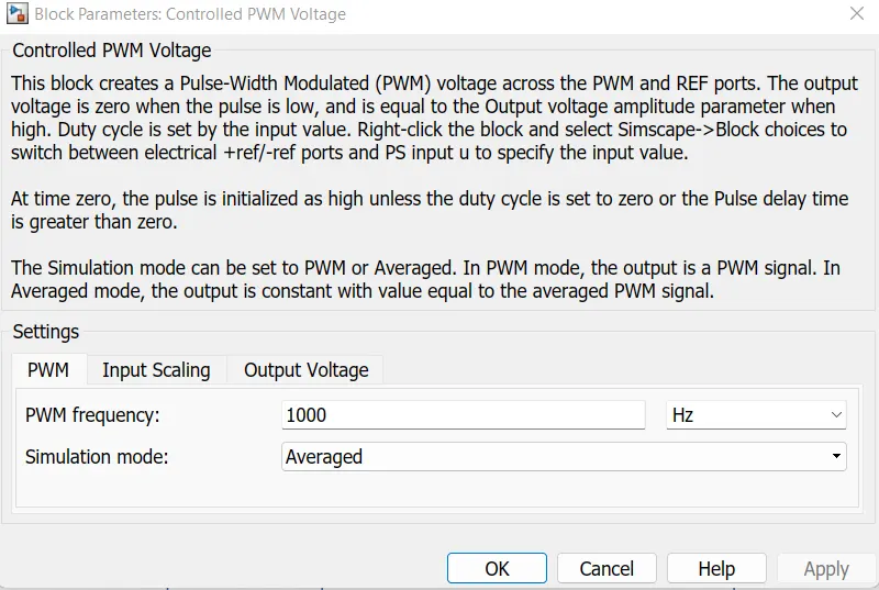
Controlled voltage source
The block represents an ideal voltage source that is powerful enough to maintain the specified voltage at its output regardless of the current passing through it. The output voltage is V = Vs, where Vs is the numerical value presented at the physical signal port.
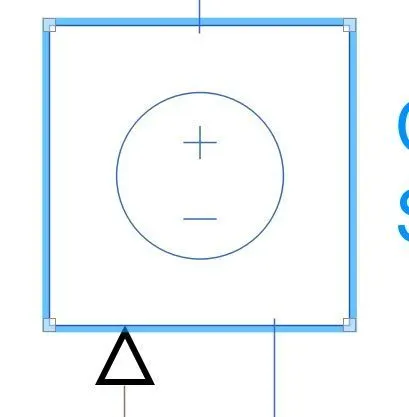
Controlled current source
The block represents an ideal current source that is powerful enough to maintain the specified current through it regardless of the voltage across it. The output current is I = Is, where Is is the numerical value presented at the physical signal port
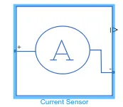
Current sensor
The block represents an ideal current sensor, that is, a device that converts current measured in any electrical branch into a physical signal proportional to the current.
Longitudinal driver
The input from the drive cycle is attached to VelRef port, the feedback is gained from the vehicle body which acts as feedback signal is connected to VelFdbk. The AccelCmd & DecelCmd are the output signal given for accelerating and braking to the vehicle. A terminator block is connected to Info port as we are not using any bus signals for this model. A constant block is attached to the Grade port as road grade angle is 0 in our case, i.e the vehicle is running at a straight road.
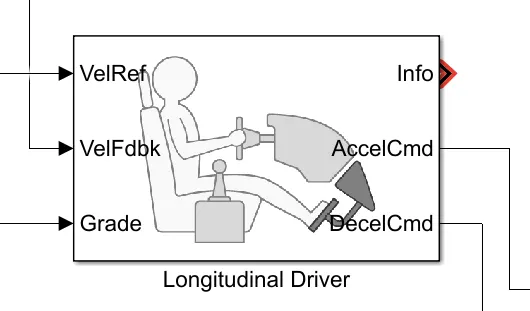
VelRef - Input port for the reference velocity signal
VelFdbk- Input port for the feedback velocity signal
Grade- Input port for the gradability to the vehicle (road grade angle)
Info- Bus signal for Gear, clutch, acceleration, etc.
AccelCMD-Output port for the acceleration signal command
DecelCmd- Output port for the deceleration or braking signal command
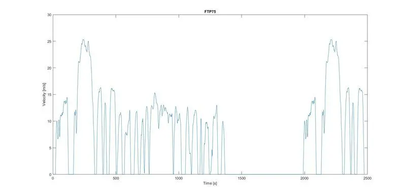
Drive cycle
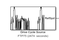
The Drive Cycle Source block generates a standard or user-specified longitudinal drive cycle. The block output is the specified vehicle longitudinal speed, which you can use to
-
Predict the engine torque and fuel consumption that a vehicle requires to achieve desired speed and acceleration for a given gear shift reference.
-
Produce realistic velocity and shift references for closed-loop acceleration and braking commands for vehicle control and plant models.
-
Study, tune, and optimize vehicle control, system performance, and system robustness over multiple drive cycle
Here FTP75 Drive cycle is used
plot of ftp 75 drive cycle
Vehicle model of electric vehicle
OUTPUT RESULTS
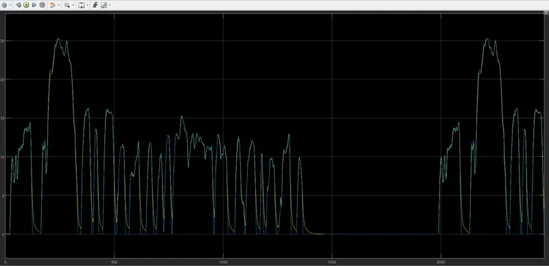
SPEED CHARACTERISTICS : It is a plot of the reference speed from the drive cycle and the feedback speed from the vehicle body.
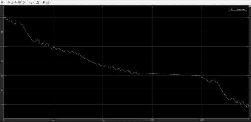
SOC% : It is the state of charge of the battery which decreases when the vehicle accelerated and slightly increases when the vehicle decelerates.
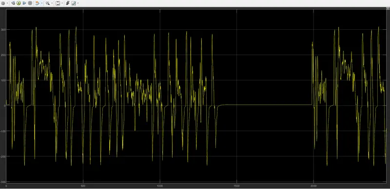
Current plot:
CONCLUSION
Made a simple and low run time model using individual component model and plotted speed characteristics state of charge and battery current of the model.in this study, the feedback speed plot and the reference speed plot overlap each other almost completely but there are regions where both the speeds are different. It is when the vehicle is decelerating.