Week-7 Challenge: DC Motor Control
Q-1)
A) Explain a MATLAB demo model named ‘Speed control of a DC motor using BJT H-bridge.
An H-bridge is an arrangement of transistors that allows a circuit full control over a standard electric DC motor.That is, an H- bridge allows a microcontroller, logic chip, or remote control to electronically command the motor to go forward, reverse,brake, andcoast 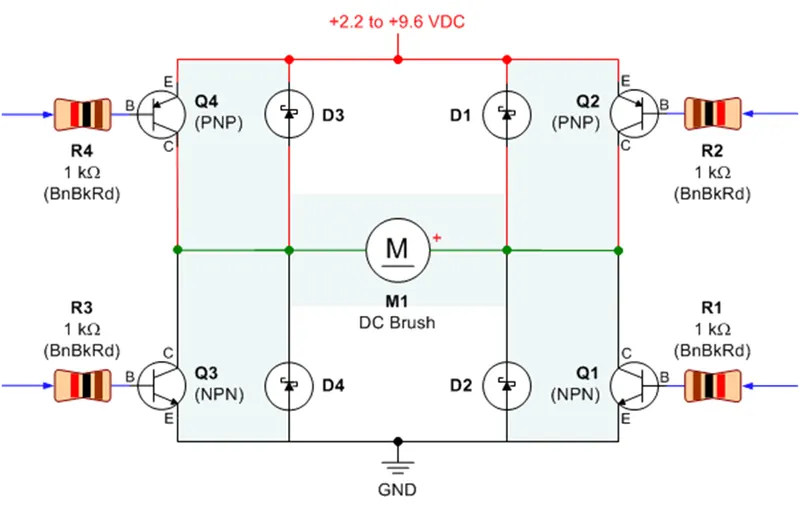
- Q1, Q3: These are NPN transistors. They connect the motor to ground (negative terminal of the battery).
- Q2, Q4: These are PNP transistors. They connect the motor to +2.2V to +9.6V (positive terminal of the battery).
- R1-R4: These resistors prevent too much current from passing through the base (labeled B) control pin of the transistor. The resistor value of 1 kilohm (1000 ohms) was chosen to provide enough current to fully turn on (saturate) the transistor. A higher resistance would waste less power, but might cause the motor to receive less power. A lower resistance would waste more power, but wouldn’t likely provide better performance for motors running on consumer batteries.
- D1-D4: Diodes provide a safe path for the motor energy to be dispersed or returned to the battery when the motor is commanded to coast or stop. I notice many H-bridge circuits on the web lack these diodes. I suppose that’s safe enough for light loads at low voltages, but without diodes, a motor voltage spike can force its way through the unprotected transistors, damaging or destroying them.
- M1: This is a direct-current (DC) motor. These are very common. You can find them in surplus stores online or in salvaged toys. The motor should have only two wires. Measure the resistance of the two motor wires using a multimeter. If the motor resistance is less than 5 ohms, then the transistor parts listed in this article are too weak to power the motor
Controlling the H-Bridge Motor Driver
The resistors are the inputs that control the H-bridge. By connecting a resistor to either +VDC or GND, it turns on or off the corresponding transistor. (+VDC is the positive end of the battery. GND is the negative end of the battery.) When a particular pair of transistors is turned on, the motor does something.
Command R1 R2 R3 R4
Coast/Roll/Off GND or disconnected +VDC or disconnected GND or disconnected +VDC or disconnect
Forward GND or disconnected GND +VDC +VDC or disconnected
Reverse +VDC +VDC or disconnected GND or disconnected GND
Brake/Slow Down +VDC +VDC or disconnected +VDC +VDC or disconnected
- there are 4 resistors, there are actually sixteen possible ways this circuit can be commanded. Don’t sweat the other variations (they’re in the book if you’re curious). Except.
- Neverapply +VDC to R1 and GND to R2 at the same time! You'll short circuit the battery.
- Neverapply +VDC to R3 and GND to R4 at the same time! You'll short circuit the battery.
Model Explanation:
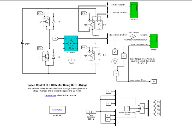
- The bipolar junction transistor (BJT) when used for power switching applications , operates as an IGBT . When it is conducting (BJT operating in the saturated region), a forward voltage Vf is developed between collector and emitter ( in the range of 1 V). Therefore , the IGBT block can be used to model the BJT device.
- The IGBT block does not simulate the gate current controlling the BJT or IGBT. The switching is controlled by a Simulink signal(1/0). The dc motor uses the preset model (5 HP 24V 1750 RPM). It simulation a fan type load (Where load torque is proportional to square of speed ).The armature mean voltage can be varied from 0 to 240 V when the duty cycle (specified in the pulse Generator block) is varied 0 to 100%.
- The H-bridge consists of four BJT/Diode pairs (BJT simulation by IGBT model). Two transistors are switched simultaneously: Q1 and Q4 or Q2 and Q3. When Q1 and Q4 are fired, a positive voltage is applied to the motor and diodes D2-D3 operate as free-wheeling diodes when Q1 and Q4 are switched off. When Q2 and Q3 are fired, a negative voltage is applied to the motor and diodes D1-D4 operates as free-wheeling diodes when Q2 and Q3 are switched off.
- The IGBTblock implements a semiconductor device controllable by the gate signal. The IGBT is simulated as a series combination of a resistor Ron, inductor Lon, and a DC voltage source Vf in series with a switch controlled by a logical signal (g > 0 or g = 0).
- The DC Machine block implements a wound-field or permanent magnet DC machine.
- For the wound-field DC machine, access is provided to the field terminals (F+, F−) so that the machine model can be used as a shunt-connected or a series-connected DC machine. The torque applied to the shaft is provided at the Simulink®input TL.
- The armature circuit (A+, A−) consists of an inductor La and resistor Ra in series with a counter-electromotive force (CEMF) E.
The CEMF is proportional to the machine speed.
E = KEω
KE is the voltage constant and ω is the machine speed.
- The diode is a semiconductor device that is controlled by its own voltage Vak and current Iak. When a diode is forward biased (Vak > 0), it starts to conduct with a small forward voltage Vf across it. It turns off when the current flow into the device becomes 0. When the diode is reverse biased (Vak < 0), it stays in the off state.
- The Pulse Generatorblock generates square wave pulses at regular intervals. The block waveform parameters, Amplitude, Pulse Width, Period, and Phase delay, determine the shape of the output waveform. The following diagram shows how each parameter affects the waveform.
- The DC Voltage Source block implements an ideal DC voltage source. The positive terminal is represented by a plus sign on one port. You can modify the voltage at any time during the simulation. DC voltage source is 300 V.
- The powerguiblock allows you to choose one of these methods to solve your circuit:
- Continuous, which uses a variable-step solver from Simulink.
- Discretization of the electrical system for a solution at fixed time steps
- Continuous or discrete phasor solution
- The powerguiblock also opens tools for steady-state and simulation results analysis and for advanced parameter design.
- The Muxblock combines inputs with the same data type and complexity into a vector output. The output mux signal is flat, even if you create the mux signal from other mux signals. However, you can use multiple Mux blocks to create a mux signal in stages.A mux signal simplifies the visual appearance of a model by combining two or more signal lines into one line. Mux signals do not affect simulation or code generation.
- The Demuxblock extracts the components of an input vector signal and outputs separate signals. The output signal ports are ordered from top to bottom. For information about creating and decomposing vectors, see Mux Signa
Output Result:
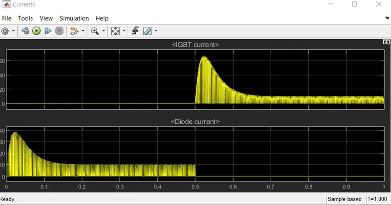
The motor starts in the positive direction with a duty cycle of 75% ( means DC voltage of 180V) At t= 0.5sec. the armature voltage is suddenly reversed and the motor runs in the negative direction. Scope shown motor speed. Armature current and load torque and current showing flowing in BJT Q3 and diode D3.When IGBT current is zero this time diode is on state ,diode current is gradually increase to 38 V. when IGBT in on state then diode off state. This time diode current is zero.
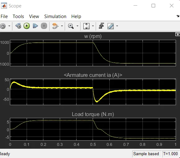
The waveform speed, armature current and load torque shown in above figure.
From the speed graph we can see that in starting speed increase to 1000 rpm then motor run in constant speed , after few cycle gradually decrease motor speed. Then motor become in stand-steel position.
From the current graph we can see at starting point suddenly increase armature current , behave like inrush current. Then after 0.5 sec current goes to negative .
When speed is increase load torque also increase , when speed decrease load torque also decrease. According to speed and armature current load torque is peak-in –nature. Laod behave w.r.t dc motor speed condition. In dc motor armature current is directly proportional to the load torque.
1.b)Comment on the armature current shoot-up from the scope results.
Simulation Output:
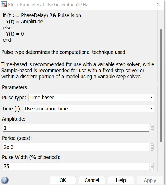
1.) Pulse Generator Parameters:
Period: 1 milli seconds
Pulse Width (% of period) : 75%
Initially, there is a spike in armature current. This is because, in a DC motor,
Ia =V-Eb/Ra where Ia">IaIais the armature current, V">V is the supply voltage , Eb">Eb is the back emf and Ra">Ra is the armature resistance.
At starting, Eb=0 as speed=0 at starting.
Therefore;
Ia=V/Ra and Ra">Ra is a very small value. Hence Ia">Ia is huge and that reflects in the graph
- In this H –Bridge circuit armature current passed through the 4 quadrant switchs (IGBT,BJT,MOSFET) and diode. The scope shows the IGBT current passed in the quadrant Q3 and D3.
- Q3 represent the IGBT current and D3 is diode current.
- During the 0.5 sec of time D3 switch is ON that are given according to the pulse generator and after the time period of 5 sec D3 switch off state.
- In starting dc motor armature gives huge amount current this is called shoot-up current.
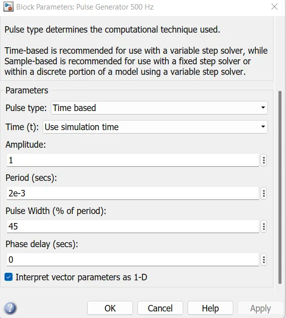
2)
1 milli seconds
Pulse Width (% of period) : 45%
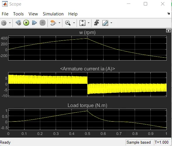
- When pulse width decrease here we can see armature current not act like shoot-up current.
- In this observation we can see current in passed through the diode and switchs for 0.5 sec. then IGBT current flow in continuous state .
- In this condition wheeling diodes when Q1 and Q4 are switched off. When Q2 and Q3 are fired, a negative voltage is applied to the motor and diodes D1-D4 operates as free-wheeling diodes when Q2 and Q3 are switched off.
Q-1)
C.) Refer to the help section of ‘The Four-Quadrant Chopper DC Drive (DC7) block’. Compare it with the H-bridge model.
The Four-Quadrant Chopper DC Drive (DC7) block represents a four-quadrant, DC-supplied, chopper (or DC-DC PWM converter) drive for DC motors. This drive features closed-loop speed control with four-quadrant operation. The speed control loop outputs the reference armature current of the machine. Using a PI current controller, the chopper duty cycle corresponding to the commanded armature current is derived. This duty cycle is then compared with a sawtooth carrier signal to obtain the required PWM signals for the chopper.
The Four-Quadrant Chopper DC Drive block uses these blocks from the Electric Drives/Fundamental Drive Blocks library:
- Speed Controller (DC)
- Regulation Switch
- Current Controller (DC)
- Chopper
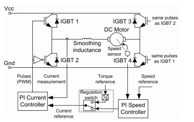
The above figure shows the schematic of the 4 quadrant chopper DC drive
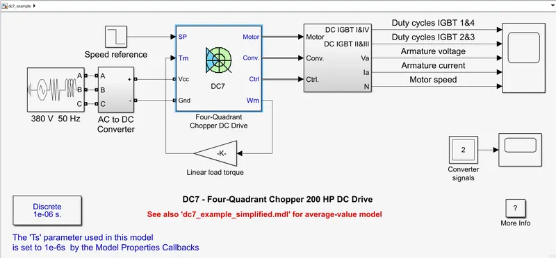
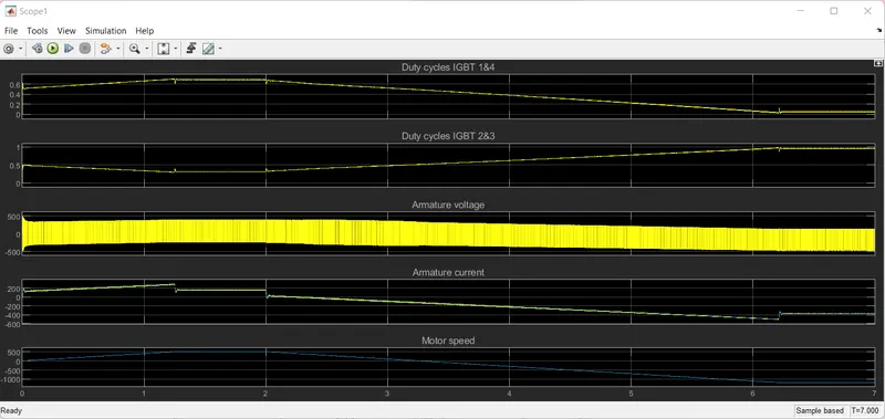
An Example of DC7 : 4 quadrant chopper 200HP DC DRIVE:
Result:-
| H bridge | Four Quadrant chopper DC drive |
| Only Two quadrants of operation are possible. They are Forward motoring and reverse motoring | It can operate in all four quadrants (forward motoring, reverse regeneration, reverse motoring, and forward regeneration) |
| Higher armature current ripple. | Lower armature current ripple due to high switching frequency of DC-DC coverters |
| Less complex | More complex |
| Simulation is continuous and simulation time is more | Discrete and Simulation time is less |
| Widely Used in Robotics | Widely used in Automobile |
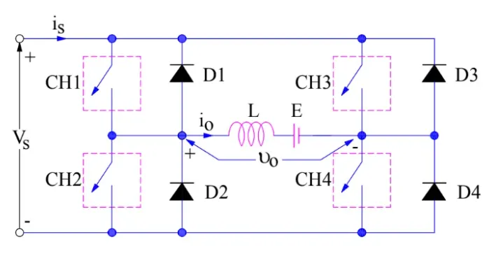
Fig 1: Circuit diagram of four quadrant chopper DC drive (DC7)
The machine is separately excited with a constant DC field voltage source. There is thus no field voltage control. By default, the field current is set to its steady-state value when a simulation is started.
The armature voltage is provided by an IGBT converter controlled by two PI regulators. The converter is fed by a constant DC voltage source. Armature current oscillations are reduced by a smoothing inductance connected in series with the armature circuit.
Working Principle:
A four quadrant chopper is a chopper which can operated in all the four quadrants. The power can flow either from source to load or load to source in this chopper. In first quadrant, a Class-E chopper acts as a Step-down chopper whereas in second quadrant it behaves as a Step-up chopper. This type of chopper is also known as Class-E or Type-E chopper. This article describes the working principle and operation of Class-E chopper with the help of circuit diagram.
* First Quadrant Operation:
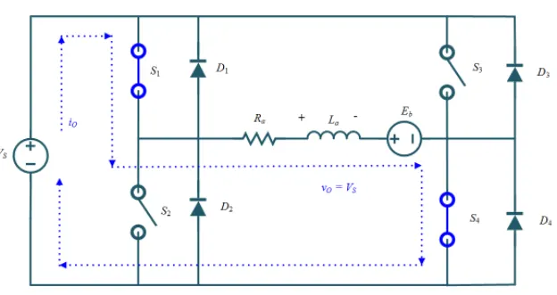
For first quadrant operation, CH4 is kept ON, CH3 is kept OFF and CH1 is operated. When both CH1 & CH4 are ON simultaneously, the load gets directly connected to the source and hence the output voltage becomes equal to the source voltage. This essentially means that vo = vs. It may be noted that the load current flows from source to load as shown by the direction of io.
When CH1 is switched OFF, the load current free wheels through CH4 and D2. During this period, the load voltage and current remains positive.
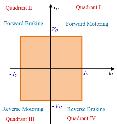
Thus, both the output voltage vs and load current io are positive and hence, the operation of chopper is in first quadrant. It may be noted that, Class-E chopper operates as a step-down chopper in this case.
* Second Quadrant Operation:
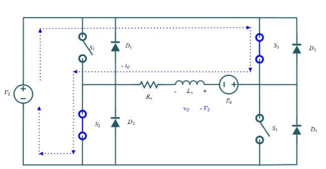
To obtain second quadrant operation, CH2 is operated while keeping the CH1, CH3 & CH4 OFF. When CH2 is ON, the DC source in the load drives current through CH2, D4, E and L. Inductor L stores energy during the On period of CH2.
When CH2 is turned OFF, current is fed back to the source through D1, D4. It should be noted at this point that (E+Ldi/dt) is more than the source voltage Vs. As load voltage Vo is positive and Io is negative, it is second quadrant operation of chopper. Since, the current is fed back to the source, this simply means that load is transferring power to the source. Kindly read Step-up chopper for detailed analysis and better understanding.For second quadrant operation, load must contain emf E as shown in the circuit diagram. In second quadrant, configuration operates as a step-up chopper.
* Third Quadrant Operation:
To obtain third quadrant operation, both the load voltage and load current should be negative. The current and voltage are assumed positive if their direction matches with what shown in the circuit diagram. If the direction is opposite to what shown in the circuit diagram, it is considered negative. One important thing to notice is that the polarity of emf E in load must be reversed to have third quadrant operation. Circuit diagram of Class-E chopper for third quadrant operation is shown below.
For third quadrant operation, CH1 is kept off, CH2 is kept ON and CH3 is operated. When CH3 is ON, load gets connected to source and hence load voltage is equal to source voltage. But carefully observe that the polarity of load voltage vo is opposite to what shown in the circuit diagram. Hence, vo is assumed negative. Let us now see what is the status of load current io. It may be seen that io is flowing in the direction opposite to shown in the circuit diagram and hence negative.
Now, when CH3 is turned OFF, the negative load current free wheels through the CH2 and D4. In this manner, vo and io both are negative. Hence, the chopper operates in third quadrant.
Fourth Quadrant Operation:
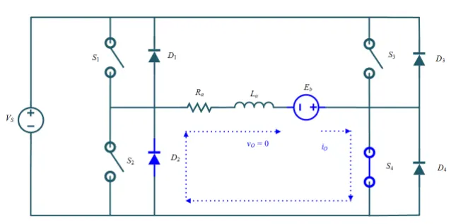
To obtain fourth quadrant operation, CH4 is operated while keeping CH1, CH2 and CH3 OFF. The polarity of load emf E needs to be reversed in this case too like third quadrant operation.
When CH4 is turned ON, positive current flows through CH4, D2, L and E. Inductance L stores energy during the time CH4 is ON. When CH4 is made OFF, current is fed back to the source through diodes D2, D3. Here load voltage is negative but the load current is always positive. This leads to chopper operation in fourth quadrant. Here, power is fed back to the source from load and chopper acts as a step-up chopper.
The operation of a four quadrant chopper or Class-E chopper is summarized in the figure below.
2. Develop a 2-quadrant chopper using simulink & explain the working of the same with the relevant results.
We will always get a positive output voltage V0 as the freewheeling diode FD is present across the load. When the chopper is on the freewheeling diode starts conducting and the output voltage v0 will be equal to Vs . The direction of the load current i0 will be reversed. The current i0 will be flowing towards the source and it will be positive regardless the chopper is on or the FD conducts. The load current will be negative if the chopper is or the diode D2 conducts. We can say the chopper and FD operate together as type-A chopper in first quadrant. In the second quadrant, the chopper and D2 will operate together as type –B chopper.
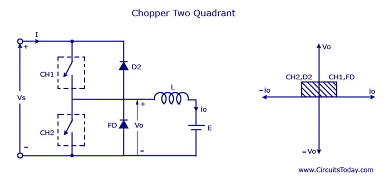
The average voltage will be always positive but the average load current might be positive or negative. The power flow may be life the first quadrant operation ie from source to load or from load to source like the second quadrant operation. The two choppers should not be turned on simultaneously as the combined action my cause a short circuit in supply lines. For regenerative braking and motoring these type of chopper configuration is used.
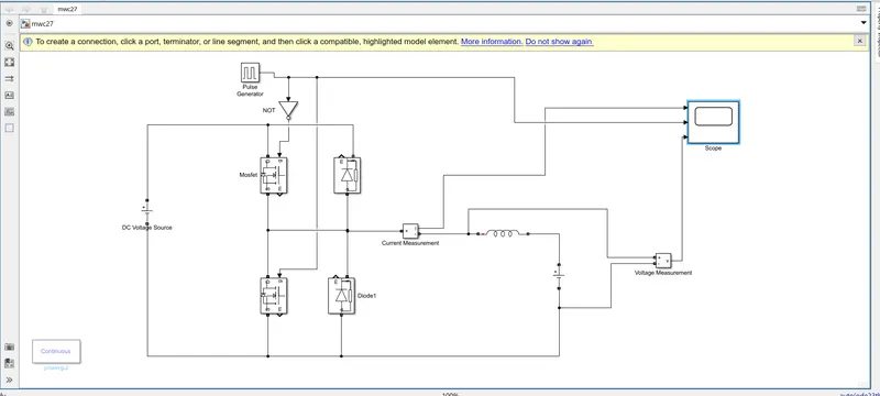
- This model have two quadrant chopper model using simulink.
- First of all we used two IGBT switch blocks and two diode . switch and diode connected in parallel condition.
- Then we connect 240 V dc voltage source with parallel. Then we connect voltage measurement block and current measurement block.
- IGBT ‘g’ terminal connect with pulse generator and not gate block.
- Then output terminal connect with scope.
- GOTO block used for Goto block passes its input to its corresponding From The input can be a real- or complex-valued signal or vector of any data type. From and Goto blocks allow you to pass a signal from one block to another without actually connecting them.
- From block used for From block accepts a signal from a corresponding Goto block, then passes it as output. The data type of the output is the same as that of the input from the Goto From and Goto blocks allow you to pass a signal from one block to another without actually connecting them.
- Then used Powergui block. The powerguiblock allows you to choose one of these methods to solve your circuit. Continuous, which uses a variable-step solver from Simulink. Discretization of the electrical system for a solution at fixed time steps Continuous or discrete phasor solutionThe powergui block also opens tools for steady-state and simulation results analysis and for advanced parameter design.You need the powergui block to simulate any Simulink model containing Simscape™ Electrical™ Specialized Power Systems blocks. It stores the equivalent Simulink circuit that represents the state-space equations of the model.
let's take two mosfet blocks and connect it as schematic.
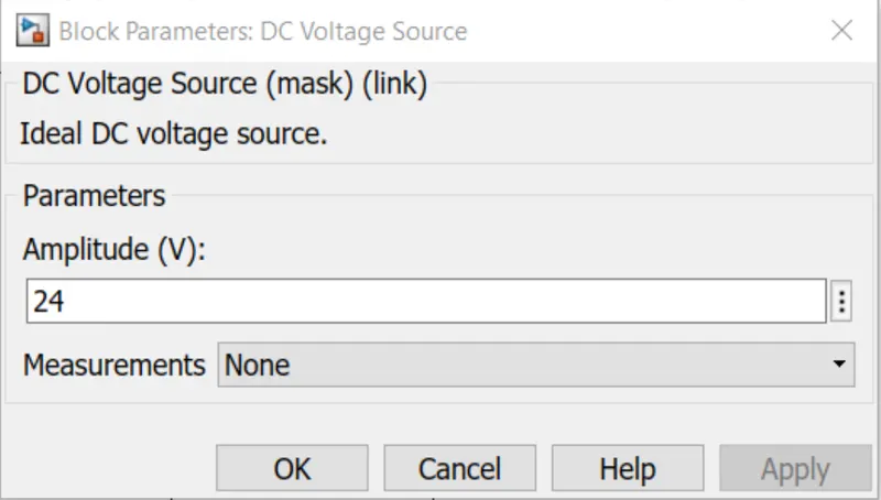
voltage source 24volts.
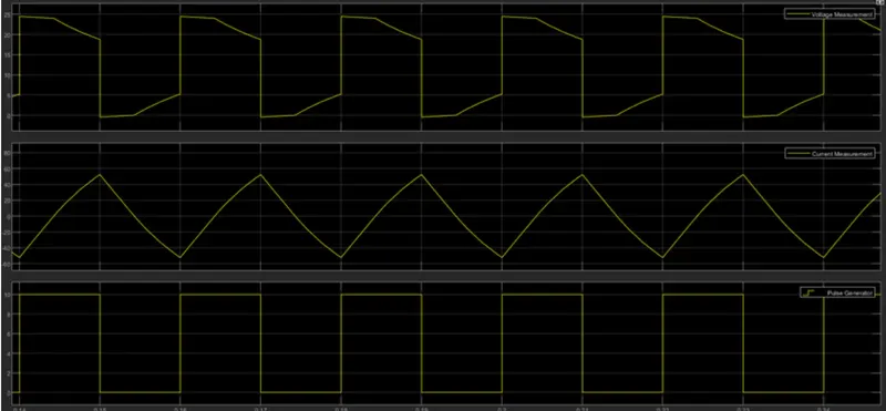
Hence, we could see clearly that the voltage is always positive but the current becomes both positive and negative. Hence, the Type C chopper is simulated and verified.
3. Explain in a brief about operation of BLDC motor.
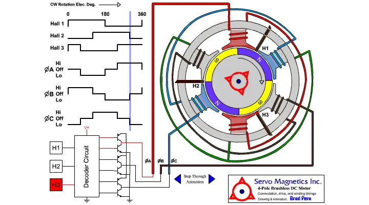
A brushless DC motor (also known as a BLDC motor or BL motor) is an electronically commuted DC motor which does not have brushes. The controller provides pulses of current to the motor windings which control the speed and torque of the synchronous motor.
These types of motors are highly efficient in producing a large amount of torque over a vast speed range. In brushless motors, permanent magnets rotate around a fixed armature and overcome the problem of connecting current to the armature. Commutation with electronics has a large scope of capabilities and flexibility. They are known for smooth operation and holding torque when stationary.
Working Principle:
- Before explaining the working of a brushless DC motor, it is better to understand the function of a brushed motor. In brushes motors, there are permanent magnets on the outside and a spinning armature which contains electromagnet is inside. These electromagnets create a magnetic field in the armature when the power is switched on and help to rotate the armature.
- The brushes change the polarity of the pole to keep the rotation on of the armature. The basic working principle for the brushed DC motor and for brushless DC motor are same i.e. internal shaft position feedback.
- Brushless DC motor has only two basic parts: rotor and the stator. The rotor is the rotating part and has rotor magnets whereas stator is the stationary part and contains stator windings. In BLDC permanent magnets are attached in the rotor and move the electromagnets to the stator. The high power transistors are used to activate electromagnets for the shaft turns. The controller performs power distribution by using a solid-state circuit.
- Basically, BLDC are of two types, one is outer rotor motor and other is inner rotor motor. The basic difference between the two is only in designing, their working principles are same.
Advantages Of Motor:-
1] It has no mechanical commutator and associated problems.
2] High efficiency due to the use of permanent magnet rotor.
3] High speed of operation even in loaded and unloaded conditions due to the absence of brushes that limits the speed.
4] Smaller motor geometry and lighter in weight than both brushed type DC and induction AC motors.
5] Long life as no inspection and maintenance is required for commutator system.
6] Higher dynamic response due to low inertia and carrying windings in the stator.
7] Less electromagnetic interference.
8] Quite operation (or low noise) due to absence of brushes.
Disadvantages of Motor:-
1] These motors are costly.
2] Electronic controller required control this motor is expensive.
3] Not much availability of many integrated electronic control solutions, especially for tiny BLDC motors.
4] Requires complex drive circuitry.
5] Need of additional sensors.
Applications of motors:-
It is used a wide variety of application requirements such as varying loads, constant loads and positioning applications in the fields of industrial control, automotive, aviation, automation systems, health care equipments, etc.