Final Project: Design of an Electric Vehicle
Aim
To design a Simulink model of an electric vehicle using Matlab software
Introduction:
An electric vehicle is propelled by an electric motor,(one or more electric
motors or traction motors). An electric vehicle may be powered through a collector system by electricity from off-vehicle sources or may be self-contained with a battery, solar panels, fuel cells, or an electric generator to convert fuel to electricity. EVs include, but are not limited to, road and rail vehicles, surface and underwater vessels, electric
aircraft and electric spacecraft.
There are four basic types of electric vehicles, which may be classed as follows. Traditional battery electric vehicles where the Motor is run by battery power only, the hybrid electric vehicle, which combines a battery and an IC engine, Fuel electric vehicle where the motor is propelled by either fuel cells or metal-air batteries. A plug-in hybrid electric vehicle is the same as a hybrid electric vehicle with a charging circuit (i.e., The Battery is separately charged)
Block diagram:
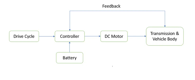
EV main blocks are Battery, drive cycle, controller, DC motor, Vehicle body, and Transmission system.
A Drive cycle is a series of data points representing the speed of a vehicle versus time or replacement of the way how the driver drives the vehicle over a period of time, these drive cycles are standard drive cycles that is used to test the vehicle's performance. There is a standard driving cycle that is produced by a country or an organization, such as EUDC, NEDC, FTP75, and Artemis Motorway 150 km/hr. In our model FTP75 and Artemis Motorway 150 km/hr are taken.
Controller: The control unit performs the main task. It controls the activities of all the components of an electric vehicle. It monitors the output of the motor and the charging of batteries. Battery stores the electric current in the form of Direct Current (DC). Also, it provides the necessary information to the driver.
Electric Motor: An electric motor provides the power to rotate the wheels. Motors may be of DC/AC type. However, AC motors are more common. But in our model, we use a DC motor.
Battery: Battery stores the electricity required to run the vehicle. The battery supplies electric current to the motor. And thus, the vehicle runs. The higher the capacity of the battery the higher the range of the electric vehicle. Most modern electric vehicles use Lithium-ion type batteries. These batteries have higher energy density. It means they are capable of storing more energy.
Transmission and Vehicle body: Electric motor shaft is connected to a simple gear where the simple gear is connected to the transmission and vehicle body.
Electric Vehicle Simulink Model:
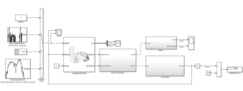
The main objective to design the EV is to calculate Soc, speed, and distance, and to compare the Ref speed and vehicle speed.
Model parameters:
Drive Cycle:
In this model, we have taken 3 types of the drive cycle. They are FTP75, Artemis motorway 150kmph and signal builder(Which is given by the user).
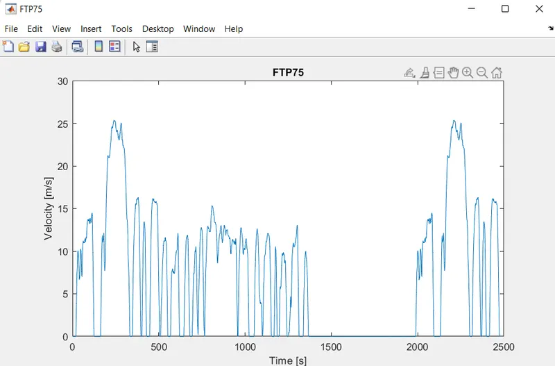
FTP75: In a drive cycle source FTP75 is selected.
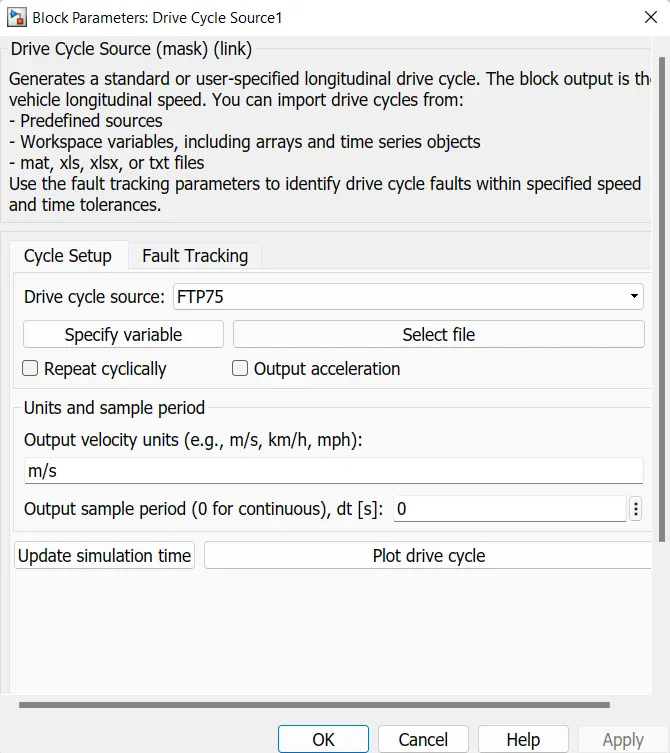
Plot the FTP75 Drive Cycle
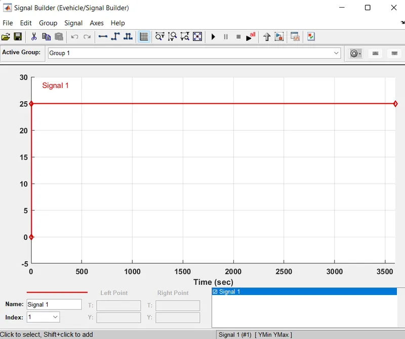
Signal builder: 25m/s is given.
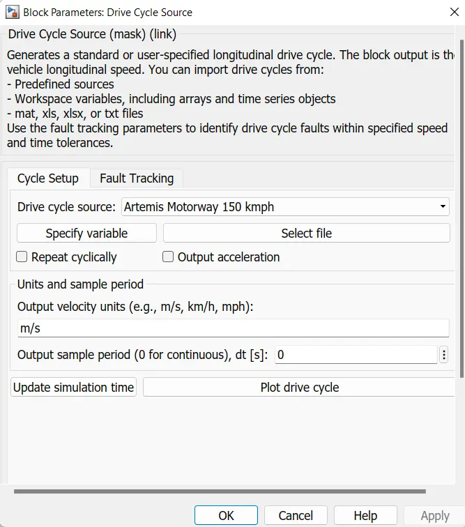
Artemis motorway 150kmph: In a drive cycle source Artemis motorway 150 km/hr is selected.
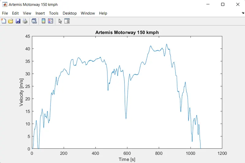
Plot the drive cycle:
The output of the drive cycle is given to the longitudinal drive cycle at VelRef port. Import drive cycles from predefined sources, Workspace variables, and mat, xls, xlsx, or txt files.
Longitudinal Driver:
The longitudinal driver will generate acceleration and braking(deceleration) commands from the input of reference speed and feedback speed. 6ports in the longitudinal driver blocks, they are named VelRef, VelFdbk, Grade, Info, AccelCmd, DecelCmd. VelRef takes input from the drive cycle, VrlFdbk takes input from the output of the vehicle body, and Grade takes input from the const block (which indicates the angle of gradian of the road).
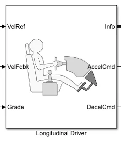
The info which gives the information of the longitudinal driver, Accelcmd, and DecelCmd output is given to the controller.
The deceleration command is given to the H-bridge controller through a controlled voltage source and the Acceleration command is given to the H-bridge controller through a controlled voltage source and PWM signal.
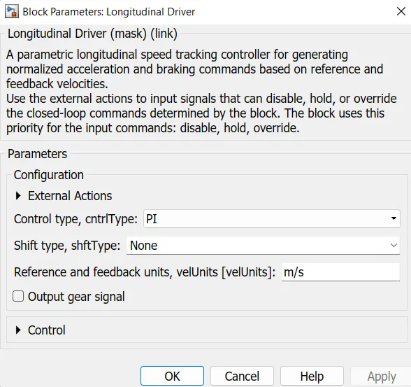
Set default parameters, Control type as PI.
Controller and Motor:
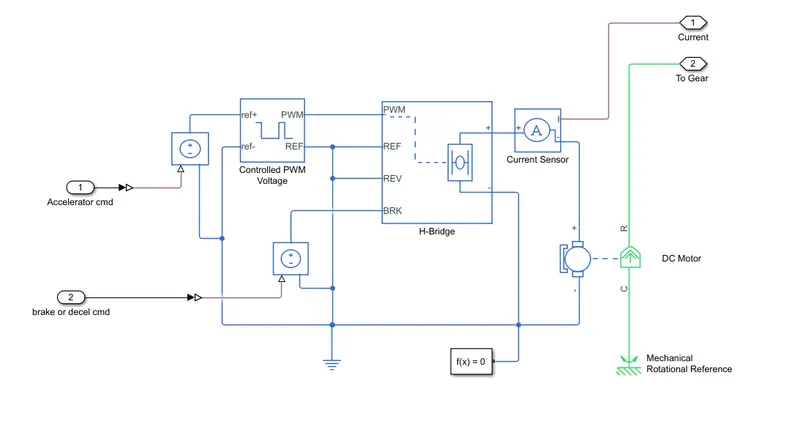
PWM
This block creates a Pulse-Width Modulated (PWM) voltage across the PWM and REF ports. The output voltage is zero when the pulse is low and is equal to the Output voltage amplitude parameter when high. The duty cycle is set by the input value. Right-click the block and select Simscape->Block choices to switch between electrical +ref/-ref ports and PS input u to specify the input value.
Parameters are set as shown below
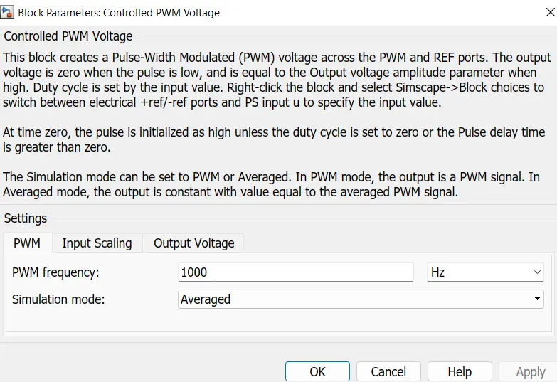
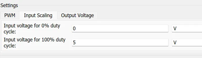
Output Voltage is set at 400V because we are using a DC motor that operates at 400V.

H-Bridge:
This block represents an H-bridge motor drive. The block can be driven by the Controlled PWM Voltage block in PWM or Averaged mode. In PWM mode, the motor is powered if the PWM port voltage is above the Enable threshold voltage. In Averaged mode, the PWM port voltage divided by the PWM signal amplitude parameter defines the ratio of the on-time to the PWM period. Using this ratio and assumptions about the load, the block applies an average voltage to the load that achieves the correct average load current. The Simulation mode parameter value must be the same for the Controlled PWM Voltage and H-Bridge blocks.
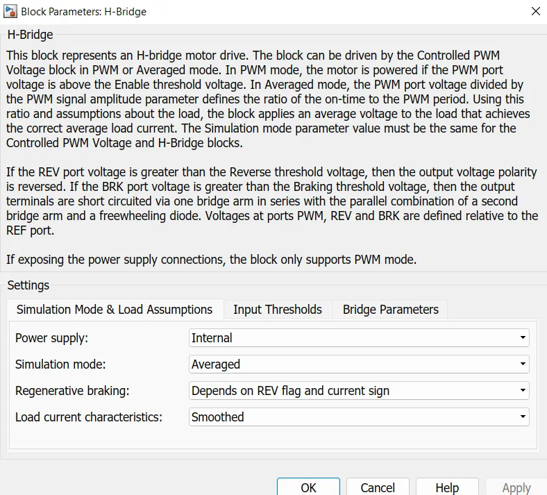
Output is sensed by the current sensor.
DC motor:
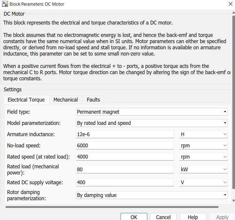
DC motor is powered and controlled by an H-bridge controller. parameters are set as shown above.
Transmission and Vehicle Body:
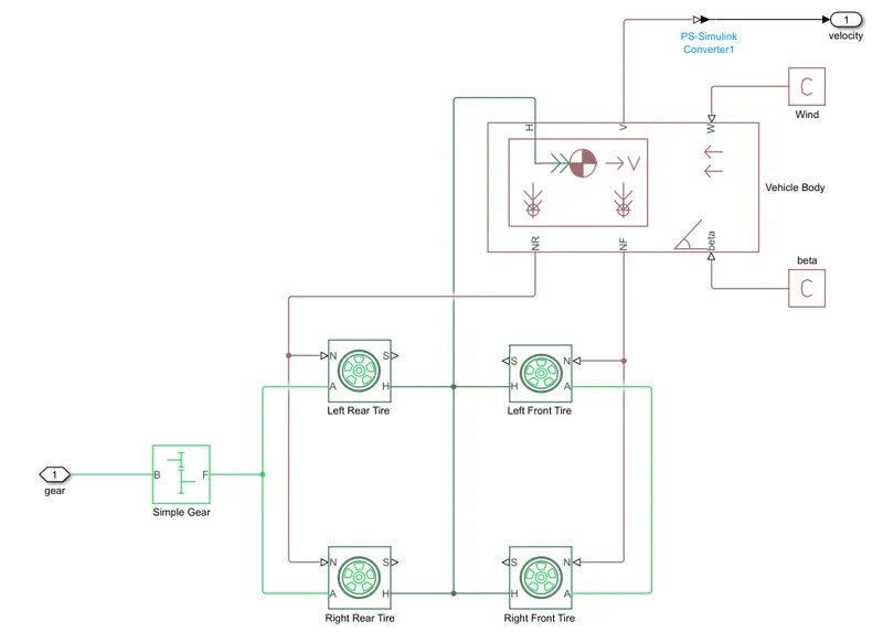
Motor rotational output is given to the vehicle body through a gear system and transmission system. The model is designed as a rear-wheel drive(RWD) system.
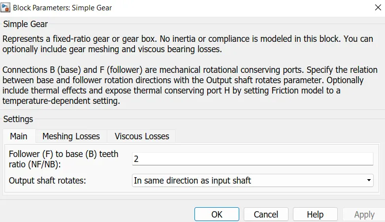
Simple Gear output is connected to the rear wheel axle. The output shaft rotates in the same direction as the input shaft.
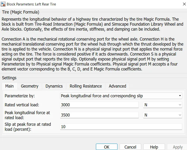
In a tire there are 4ports, they are N, A, S, and H. N is the Normal force acting on a tire, 'A' is a mechanical rotational conserving port for the wheel axle, S is the Tire slip and, H is the Wheel hub
parameters are set to default:
Vehicle Body:
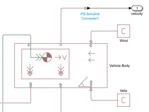
It has six ports they are NR, NF, H, V, beta, and W.
NR is a Normal wheel force on the rear (Connected to the rear tires).
NF is a Normal wheel force on the front(Connected to the front tires).
H is the Horizontal motion of the vehicle body which is connected to all the tires H port
V is the Output velocity of the vehicle which is shown in the scope and converted into the distance in km
beta is the road inclination angle(PS Constant block set as 0).
W is the headwind speed(PS Constant block set as 0).
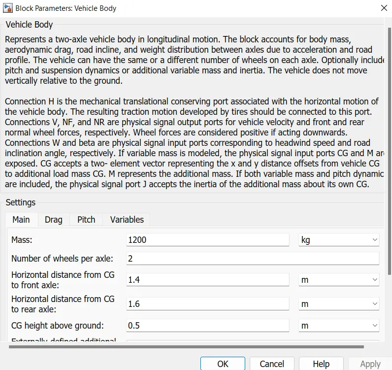
parameters are to set default:
Battery:
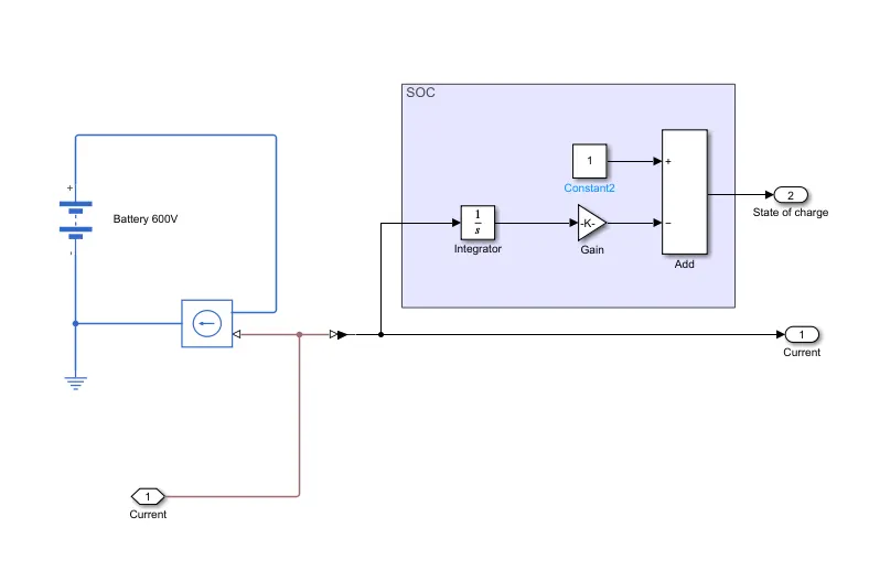
The output of the current sensor is given to the battery through the controlled current source.
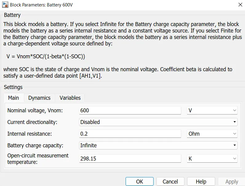
Assume battery voltage is 600V and set all parameters as default.
State of charge:
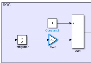
The columb counting method was used to know the SOC of the battery.
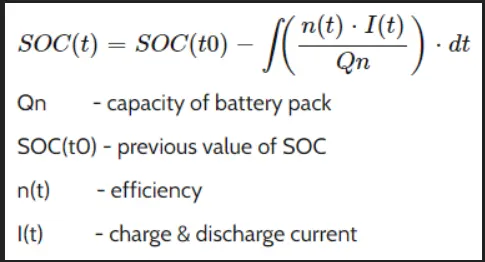
Ampere hour is converted to ampere through the integrator.
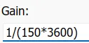
Assume battery capacity is 150Ah and efficiency is 1.
Using gain block battery capacity is included.
Initial SOC is 1 which is subtracted with gain then we get the current soc of the battery.
Result:
Vehicle velocity is seen by the scope when it is connected to vehicle body velocity.
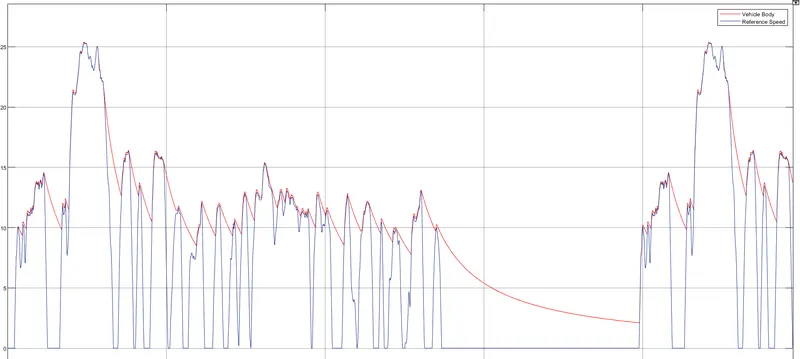
The red color indicates the velocity of the vehicle and the dark blue color indicates the reference speed of the drive cycle. There is a delay in acceleration and braking in the vehicle velocity.
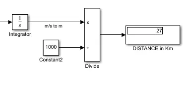
Speed converted to distance: Integrating the velocity we convert m/s to m, then m converted to Km by dividing 1000.
27km traveled by FTP75 drive cycle with 150ah battery capacity.
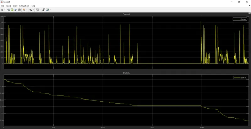
State of Charge: Plot 1 shows the current and plot 2 shows the SOC of the battery.
SOC change from 1 to 0.8778 for FTP75 drive cycle for a 150ah battery capacity.
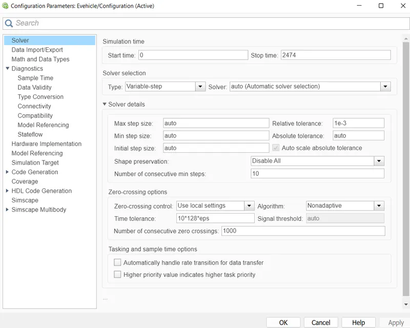
System level configurations: parameters are set as shown below.
Conclusion:
Hence, the Simulink model for an electric vehicle is created, for the FTP75 Drive Cycle, with the motor voltage of 400v and battery pack capacity of 150Ah we get the output of vehicle speed, Distance traveled by the vehicle(27km), and SOC(0.8778) of the battery.