Final Project: Design of an Electric Vehicle
AIM- To make and understand a System level matlab model of Electric vehicle using powertrain blockset.
COMPONENT USED-
Driving cycle block, Longitudinal Driver, controller, Mapped Battery, Mapped DC motor, Drivetrain & vehicle, some Basic simulink blocks.
CONTROLLER- constant blocks, from & goto, add block, product block, 1D-Lookup table, min/max logic etc.
DRIVETRAIN- Open Differential, Rotational Inertia, Torsional Compliance, Longitudinal Wheel, Vehicle Body 1DOF Longitudinal, Two way Connection.
BASIC SIMULINK BLOCKS- Bus Creator, Bus Selector, MUX, DeMUX, Gain blocks, Scope, Goto and from tags.
THEORY-
We know the Simulink environment is best for testing, analysing and designing of new and innovative changes of physical model as it cost very less compare to the real-world model testing. Our aim is to understand and prepare detailed report of the Vehicle model in order to learn how MATLAB Simulink models work.
The system level modeling includes Powertrain along with the controller modeling, so to make a detailed model of electric vehicle we use Powertrain blockset.
POWERTRAIN BLOCKSET-
Powertrain blockset provide library of automotive components as well as preassembled motor dynamics. It also includes a component library for simulating engine subsystems, transmission assemblies, traction motors, battery packs, and controller models.
This model mostly contains Powertrain blocks that is mapped model of battery and motors and Torque-speed compliance and vehicle dynamics with the disc brake wheel.
FORWARD FACING MODEL-
We use Forward facing model. It implies the vehicle model that follow driving cycle with necessary control strategy and end up in giving Power requirement of vehicle to follow a certain driving cycle. The Forward-facing model requires modelling of Driver either predictive or PI based. The Actual speed of vehicle is never matched with the Reference speed driving cycle. Unlike Backward facing model the speed of vehicle is controlled by driver dynamics that gives error just like in real case, where Driver perform a series of task to test the vehicle.
Forward facing model gives Dynamic performance of the vehicle and it is used in the developing stage of Vehicle. It provides insight of the vehicle model and it captures limit of the physical system. It also makes control development easier.
DATASHEET MODELS-
Datasheet of any electrical/mechanical component is provided by the manufacturer and it has the results of different test performed in the manufacturing product.
DATASHEET BATTERY
The datasheet of the lithium-ion battery includes its performance with respect to the SoC that is Its Voltage vector and Impedance matrix along with efficiency mapping.
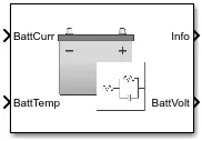
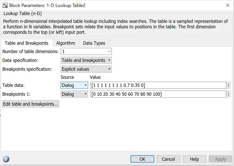
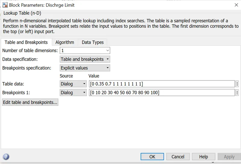
Battery of the Electric vehicle can be tricky so we directly take manufacturer data and model the Lithium-ion battery. also we imlement the charging and discharging logic table as per the state of charge(SoC) of the battery.
DATASHEET MOTOR-
Datasheet of DC Motor implies Torque speed characteristics that is Constant torque region and Constant Power region of operation, all the necessary modeling adjustment is done by block itself.
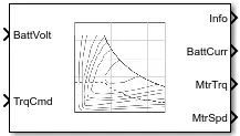
The torque command is given to this motor block with feedback of motor speed. The corresponding motor operating point parameters are calculated and motor will draw current accordingly and power the vehicle according to the motor dynamics.
We take a DC motor with maximum Torque of 400 Nm and maximum power of 165kW and torque constant of 0.2 so we can calculate the speed at the maximum power operating point.
critical speed = `P/(T(max))`
`omega=165000/400`
`omega=412.5` rad/s
or 3941 RPM
so we can make a array of speed and torque in order to model the DC motor
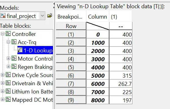
N = [0 1000 2000 3000 4000 5000 6000 7000 8000]
T = [400 400 400 400 400 315 262.7 225 197]
DRIVETRAIN-
Drivetrain is the series of component of the electric vehicle that delivers power to the Driving wheel and It connects transmission to the drive axles. It doesn't include the Motor or engine model.
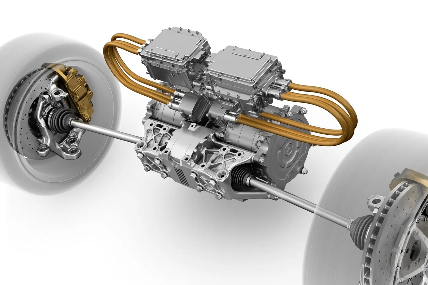
Drivetrain includes Differential, It is the differentials that make it possible for the wheels in a moving car to spin at different speeds otherwise the wheels moves in same speed regradless of vehicle take turn. without the differential vehicle is in potential disaster while makinf swift turn.
VEHICLE BODY-
Vehicle body is in direct contact with the environment so various terrain condition have to simulate like inclined plane and wind effect and drag forces.
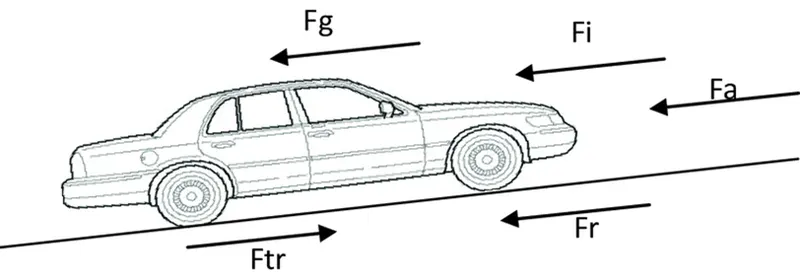
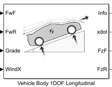
the normal face of tire indicates the power transfer direction from the engine and all other forces like friction, wind and gravitational forces depends upon terrain and environmental conditions. (xdot implies velocity of the vehicle)
OPERATION-
We model different aspects of the vehicle including enviroment and Forward facing model of the vehicle. take a quick look at the final model that I made using powertrain blockset.
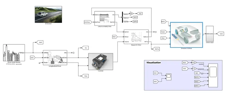
Here we can see the Longitudinal Driver that try to run the vehicle according to the input ie. Driving cycle given to it. The longutudinal driver will give accelerating command and deaccelerating command in order to reduce the error between vehicle speed and desired speed.
Then this Acclerating and Deaccelerating command is given to the controller that will convert these signals to the Motor torque command given to the motor. Now we take a look at insight of the controller....
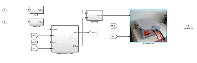
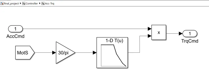
Motor controller have Different blocks to modify the signal and to model control logic of the Vehicle. So firstly we take accelerating command and convert into the torque command by using Speed-Torque characteristics of the motor.(lookup table is used to model)
The table data is given below
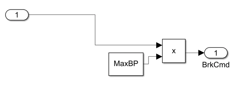
the brake command is made by multiplying deaccelerating cmd to the maximum Brake Pressure.
Now we implement the Regenerative Braking controller. The Regenerative capacity of the vehicle depends on regenrative/negative current of battery(Battery charging limit) and the speed of the motor(E=k*N) so the regenerative factor is generated.
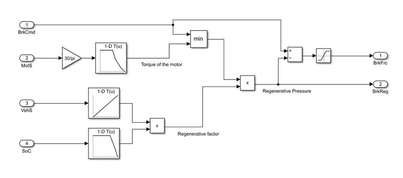
Corresponding to the speed of the motor, respective torque can be calculated with respective to the speed torque characterstics and minimum of the break command and motor torque is given to the regenerative factor that gives Regenerative torque and by substracting the Brake command with the regenerative pressure torque gives the Friction brake Required in order to meet the Brake requirement.
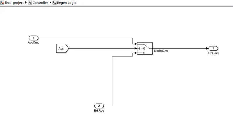
Now Regenerative logic is nothing but the control stretagy that is Regenerative braking is applied as soon as the driver lift the acceleration padel. so we can model this logic by a controlled switch.
Now the motor controller. There are 3 input to the motor controller that is Torque command, Motor speed and SoC of the battery. The SoC is required to calculate the Battery charging limit and Battery discharging limit than this limits are compared with the Power command(Torque command*Motor speed){`Power=T*omega`}
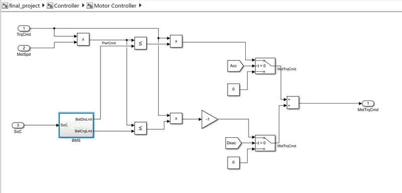
So if the Accelerating Power command(power required by the driver) is less than the Battery discharging capacity at that time than the Acceleration Torque command can be given to the motor and if Regenrative Power command is less than or equal to the Battery charging limit at that time then the Regenerative Torque command can be given to the motor (ie. negative in nature).
The deciding factor for selecting either Acclerating command or the Regenerative torque command is done by implementing a logic that restrict the Accelerating Torque when the Accelerating command is zero and same logic goes for the Regenerative Torque command. this is done by a controlled switch that passes the respective Torque command when their respective Acc/Desc signal is high otherwise it passes zero.
This Addition of both Accelerating Torque command and Regenerative Torque command is given as the Motor torque command so that motor can follow the Accelerating and Deaccelerating operation.
Now the motor part,
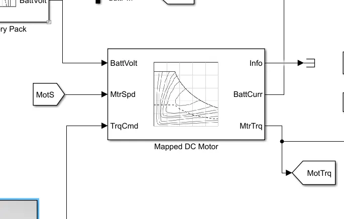
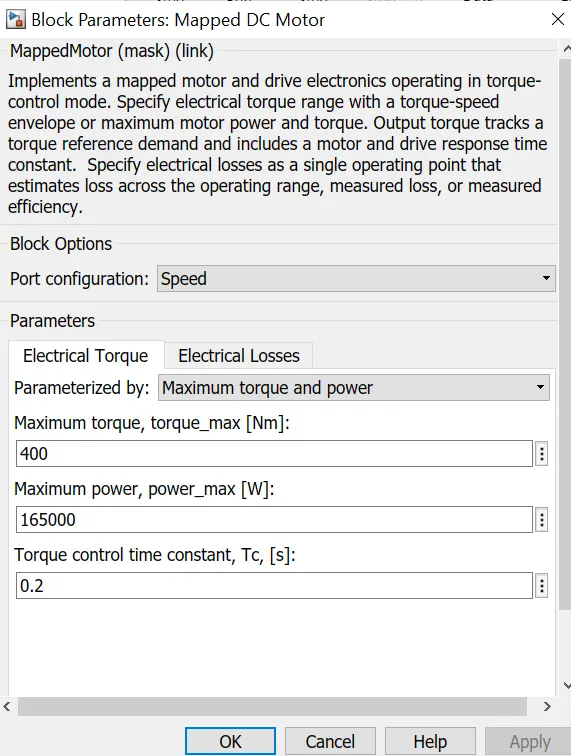
motor have different Input ports like Battery voltage and Torque command with Motor speed feedback so that the motor block can calculate the operating point and corresponding battery current and output Torque i.e. further given to the Drivetrain of the vehicle.
Now take a look at the Drivetrain and vehicle modelling part,
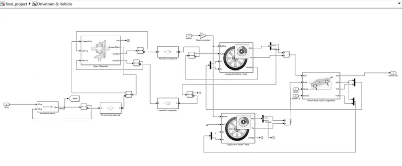
Here we can see the main components that is Rotatioal Inertia, Open Differential, Longitudinal wheels and 1DOF Vehicle model are interconnected by means of Torque compliance and Two way connections.
Here we can see only Front wheels are modeled here because we take only one wheel for both front and rear because other wheels are experiencing same forces like its brother wheel so the Normal force on the wheels are added two times so we can model all wheels without complecating our model.
Here we can see the motor torque first come to the rotational inertia then it passes through the differential which supplies power to the front wheels and all the wheels are connected to the vehicle body and experience all forces that a vehicle body are going through.
last but not least the Friction Braking command is given to the Wheels with a suitable Biasing factor that we take a constant here, so that we do not have to worry about implementing braking system and make model a little simple for time being.
MODEL PARAMETERS-
we assume some of the model parameters to meet the Requirement of the vehicle and these parameters are shown in a table below.
| S.N. | MODEL PARAMETERS | VALUE |
| Longitudinal Driver | ||
| 1. | Control type | Predictive |
| 2. | Shift Type | Reverse, Neutral, Drive |
| Mapped DC Motor | ||
| 3. | Maximum Torque [Nm] | 400 |
| 4. | Maximum Power [kW] | 165 |
| 5. | Torque constant | 0.2 |
| Mapped Battery | ||
| 6. |
Battery Charge Max [Ah] |
100 |
| 7. |
Voltage table data [1x101] |
[2.8 ----- 4.22] |
| 8. |
Open circuit voltage breakpoints [1x101] |
[0 ------ 1] |
| 9. |
Internal Resistance Table data [1x101] |
data from reference model |
| 10. |
Battery temp breakpoints [1x7] |
[243.1 ----- 313.1] |
| 11. |
Battery capacity breakpoints [1x6] |
[0 0.2 0.4 0.6 0.8 1] |
| 12. |
Number of cells in series |
96 |
| 13. |
Number of cells in parllel |
2 |
|
1 DOF Vehicle Body |
||
| 14. |
mass [kg] |
1500 |
| 15. |
Drag Coefficient [Cd] |
0.3 |
| 16. |
Frontal area [m^2] |
4 |
|
Enviroment |
||
| 17. |
Ambient Temperature [K] |
300 |
| 18. |
Gradient |
0 |
| 19. |
Wind velocity [m/s] |
0 |
all other parameters are same as the initial values as we don't have the accurate vehicle data so we run the simulation for initial guess that is available in the library itself. we can further modify these data according to the test requirement. here we take readily available data for time being.
RESULTS-
Now its time to run the model. For simplicity firstly we take the Japanese 10 Mode (135sec) driving cycle. which is a short duration Driving cycle that is available in the Driving cycle package.
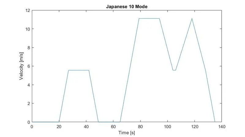
here we can see the vehicle runs for 2 times firstly for high acceleration and low speed i.e. around 6 m/s (21km/h) and secondly for high acceleration and high speed with rapid deacceleration with max speed of 11m/s (40km/h).Now take a look at the Driving Resultant Graph in Visualization area.
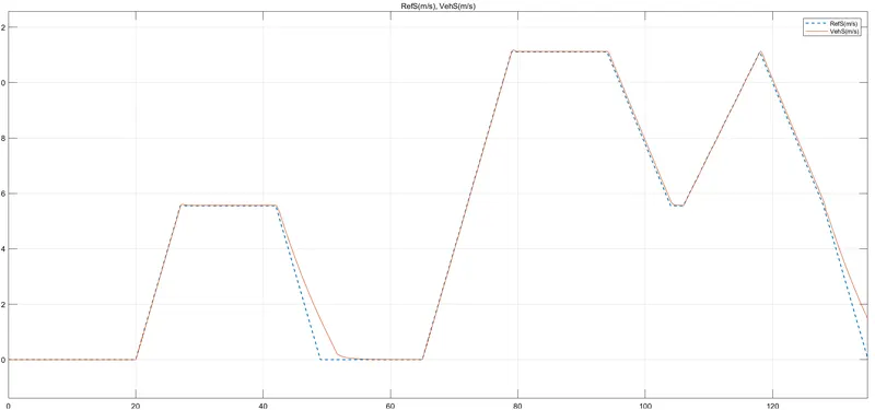
here we can see the dotted line showing the reference speed and orange line shows the actual speed of the vehicle which is lagging behind at the Deacceleration period which can be corrected by increasing the mechanical brakes power.
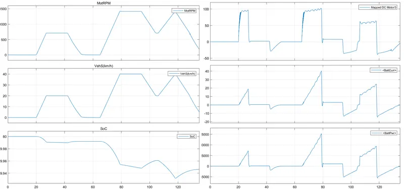
Now take a look at this graph we can see in accleration period the Battery current is positive(draw) that reduces the SoC of the battery but in the Deacceleration period the Battery current and power are negative(supply) that increases the SoC of the battery by charging it.
Here we can see the Accelerating Power is huge compare to the Regenerative power with almost same accelerating and deaccelerating graph. It is because in this driving cycle Vehicle amost runs in low speed so the EMF induced(back emf of constant flux motor) is Low that is have limited power transfer capability from motor to the load. But by using intellegent Brakes which can increase magnetic flux(`TpropI*phi`) at starting can result in High regenerative braking.
Now as we understand the working properly, We can now run the model for FTP 72 (1372sec).
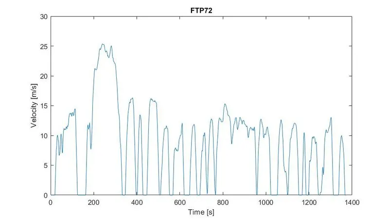
This driving cycle is comparetively more challanging and have high Acceleration and Deacceleration demands so we look at the performance of the vehicle for this driving cycle
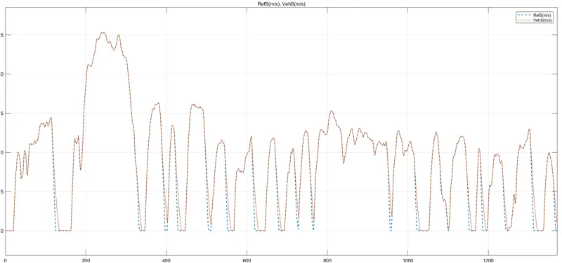
here we can see the actual vehicle speed in deacceleration is lagging behind and could not succesdully satisfy the driving cycle so we increase the mechanical braking in order to have satisfactory braking(Note- Plugging is not used in this model).
Now run again the FTP 72 driving cycle.
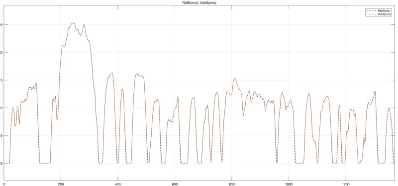
Now by increasin the mechanical braking we have satisfactory braking and vehicle almost follow the Requirement of the FTP 72 Driving cycle. Now take a look at different aspects of this iteration.
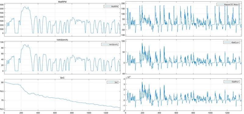
Here we can see, This driving cycle includes high speed operation and It gives Higher power requrements to the battery so SoC will drop drastically as vehicle experience more accelerating and deaccelerating conditions. The SoC at the end of this driving cycle is 78.5%(approx). Battery current goes maximum to the 90amp and Battery power is around 35000 watts at max.
we can futher modify the model for better results and can include plugging to the vehicle to have better Braking.
CONCLUSION-
We successfully made a System level matlab model of Electric vehicle using powertrain blockset and take results. We also comment on the results to increase the performance of the current model. The development phase of the Electric vehicle can be analysed by this model and we vcan use different stretagy for improving the model by understanding this model.