Final Project: Design of an Electric Vehicle
EV Live Batch 13
MATLAB model of Electric Car
Aim
Build a MATLAB model of electric car which uses a battery and a DC motor. Choose suitable blocks from Powertrain block set and prepare a report about the model.
Introduction
An electric vehicle (EV) is an automotive vehicle that uses one or more electric motors for propulsion. It can be powered by a power source, with electricity from extravehicular sources, or it can be powered autonomously by a battery. EVs include, but are not limited to, road and rail vehicles, surface and underwater vessels, electric aircraft and electric spacecraft.
Electricity was among the preferred methods for motor vehicle propulsion, providing a level of comfort and ease of operation that could not be achieved by the gasoline cars of the time. Internal combustion engines were the dominant propulsion method for cars and trucks for about 100 years, but electric power remained commonplace in other vehicle types, such as trains and smaller vehicles of all types.
EVs have seen a resurgence due to technological developments, and an increased focus on renewable energy and the potential reduction of transportation's impact on climate change, air pollution, and other environmental issues. Project Drawdown describes electric vehicles as one of the 100 best contemporary solutions for addressing climate change.
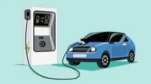
The power and performance of the EV depents on the motor and battery. BLDC or Inductions motors and Lithium- Ion batteries are commonly used in EV's.
MATLAB Simulink Model Creation
Main Components of an EV:
- Motor
- Battery
- Power Convereters
- Transmission system
- Wheels
Simulink Model of Electric Vehicle
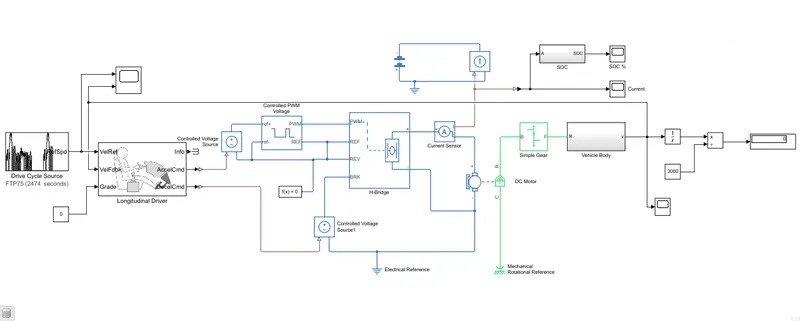
The components used in the designing of model:
- Drive cycle source
- Longitudinal driver
- Control voltage sources
- Controlled PWM Voltage
- H - Bridge
- Current Sensor
- DC Motor
- Controlled current source
- Battery
- Solver Function
- Constant Block
- Scope
- Integral
- Display
- PS-Simulink Convereter
- Simulink-PS Convereter
For SOC Estimation Subsystem:
- Rate Transistion
- Gain
- Discrete Time Integrator
- Arithematic operatoe (Sum)
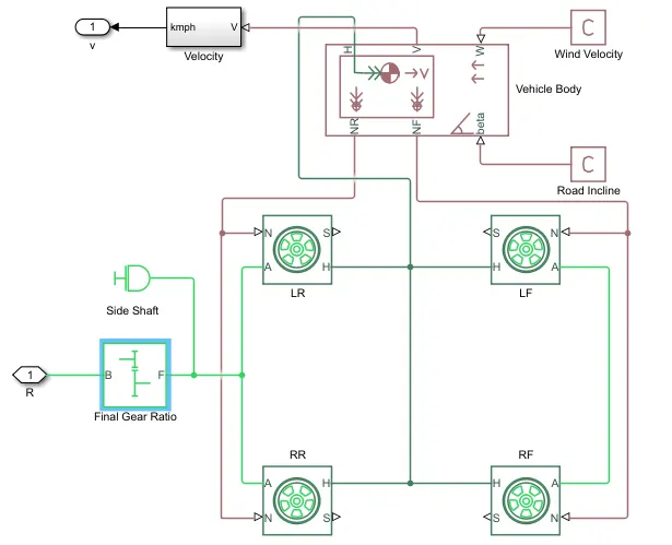
For Vehicle Body Subsystem:
- Simple Gear
- Tire(Magic Formula)
- Vehicle body
- PS - Constant
For Velocity Calculation:
- Gain
- Zero Order Hold
Modelling of Vehicle Body
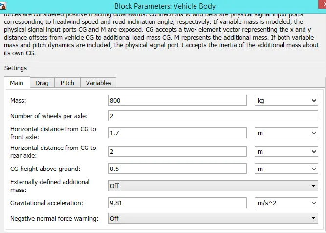
Vehicle Body Block Parameters:
Represents a two-axle vehicle body in longitudinal motion. The block accounts for body mass, aerodynamic drag, road incline, and weight distribution between axles due to acceleration and road profile. The vehicle can have the same or a different number of wheels on each axle. Optionally include pitch and suspension dynamics or additional variable mass and inertia. The vehicle does not move vertically relative to the ground.
Connection H is the mechanical translational conserving port associated with the horizontal motion of the vehicle body.
Connections V, NF, and NR are physical signal output ports for vehicle velocity and front and rear normal wheel forces.
Connections W and beta are physical signal input ports corresponding to headwind speed and road inclination angle.
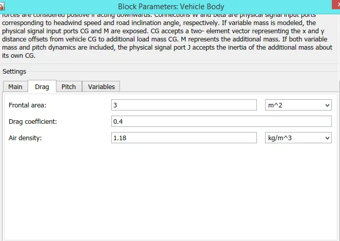
The Parameters of the vehicel body is set as :
Velocity Calculation Subsystem:
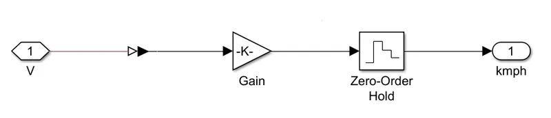
Gain - 1.61
Zero Order Hold - 0.01 (Hold input for the sample period)
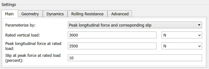
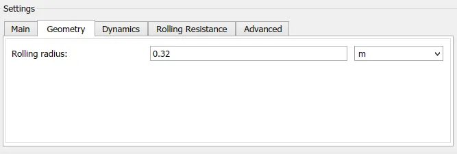
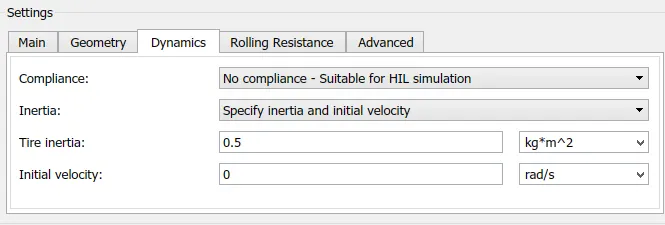
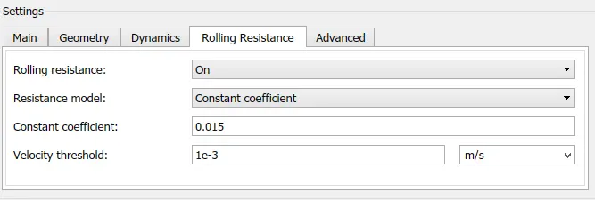
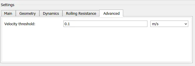
Tire (Magic Formula) Parameters:
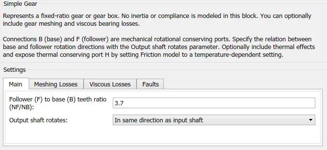
Simple Gear Parameters:
Configuration of Battery and SOC:
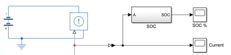
Battery Nominal Volatge - 400
Internal Resisitance - 0.2
SOC Subsystem:
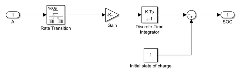
Gain Value - 1/(80*3600)
Rate Transition - Handle data transfer between different rates and tasks.
Discrete tiem integrator - Discrete-time integration or accumulation of the input signal.
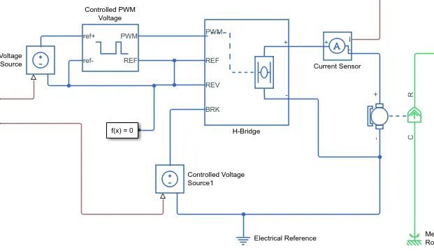
Electrical System of EV:
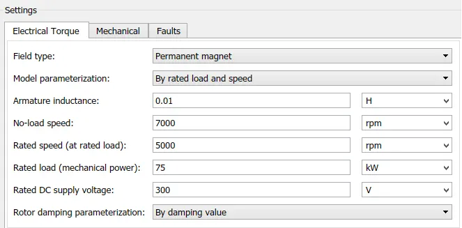
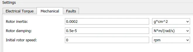
DC Motor Parameters:
When a positive current flows from the electrical + to - ports, a positive torque acts from the mechanical C to R ports.
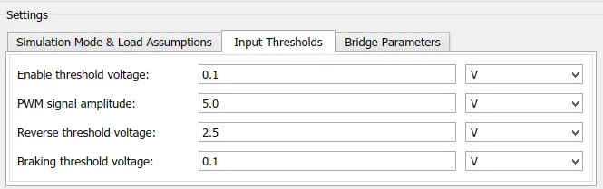
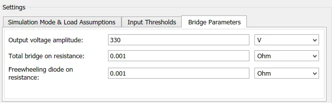
H- Bridge Parameters:
The BRK port voltage is greater than the Braking threshold voltage, then the output terminals are short circuited via one bridge arm in series with the parallel combination of a second bridge arm and a freewheeling diode. Voltages at ports PWM, REV and BRK are defined relative to the REF port.
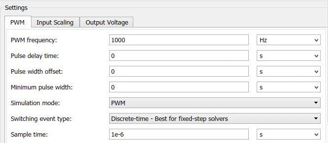
Cotrolled PWM Voltage Parameters:
This block creates a Pulse-Width Modulated (PWM) voltage across the PWM and REF ports. The output voltage is zero when the pulse is low, and is equal to the Output voltage amplitude parameter when high. Duty cycle is set by the input value. Right-click the block and select Simscape->Block choices to switch between electrical +ref/-ref ports and PS input u to specify the input value.
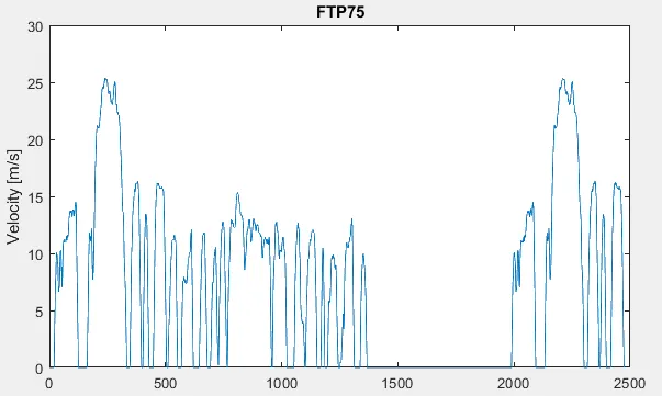
Drive Cycle Plot:
Output
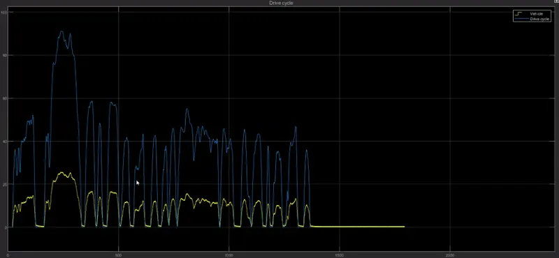
- Output of the Drive cycle and Vehicle
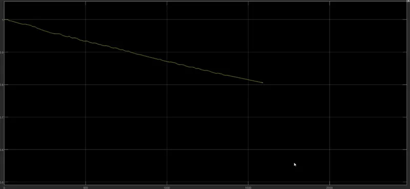
- Ouput plot of SOC Estimation
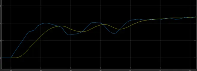
- Output plot of Referance speed(Blue) and Vehicle Speed(Yellow)
Conclusion
The Electric vehicle model is succesfully modelled using the MATLAB Simulink and the Output;
- Velocity of Vehicle
- Distance Travelled
- Current
- SOC
- Duty Cycle
The battery is having a nominal voltage 400v and the battery ampere per hour rating is 50 by which we calculated the SOC of battery.