Final Project: Design of an Electric Vehicle
Create a MATLAB model of electric car which uses a battery and a DC motor. Choose suitable blocks from Powertrain block set. Prepare a report about your model including following:
Objectives:
1. System level configurations
2. Model parameters
3. Results
4. Conclusion
Answer:
Electric Vehicle
An electric vehicle (EV) is defined as a vehicle that uses an electric motor or a traction motor for propulsion instead of internal combustion used by conventional vehicle. Electric vehicles use electricity for power instead of fossil fuels like conventional vehicles. So they do not produce any exhaust gases and pollution. The power needed in the EV come from batteries, generator or any collector system. Batteries fitted in the EV are of high energy densities in order to meet the power requirements and range.
The power of a vehicle's electric motor, as in other vehicles is measured in kilowatts (KW). 100 KW is roughly equal to 134 horsepower but electric motor can deliver their maximum torque over a wide RPM range. This means that the performance of a vehicle with a 100 KW electric motor exceeds that of a vehicle with 100 KW internal combustion engine, which can only deliver its maximum torque within a limited range of engine speed. Energy is lost during the process of converting the electrical energy to mechanical energy. Approximately, 90 % of the energy from the battery is converted to mechanical energy, the losses being in the motor and the drivetrain. Usually DC electricity is fed into a DC/AC inverter where it is converted to AC electricity and this AC electricity is connected to a 3 phase AC motor. For electric train and for some electric car, DC motors are often used. In some cases, universal motors are used and then AC to DC may be employed. In recent production vehicles, various motor types have been implemented; for instance, induction motors within Tesla electric vehicles and permanent magnet machines in the Nissan Leaf and Chevrolet Bolt.
Most large electric transport systems are powered by stationary sources of electricity that are directly connected to the vehicles through wires. Electric traction allows the use of regenerative braking, in which the motors are used as brakes and becomes generators that transform the motion of usually a train into electric power that is then feedback into the lines. The system is particularly advantageous in mountainous operation, as descending vehicles can produce a large portion of the power required for those ascending. This regenerative system is only viable if the system is large enough to utilise the power generated by descending vehicles. In order for EVs to dominate the automotive industries, there is need to be more convinient ways for consumer to be able to charge their vehicles. Thers needs to be several charging stations on highways and this can be supported if most of the houses are solar powered EVs cost more than the conventional vehicles because of the high cost of batteries and electric components.
HEVs combine an IC engine with an electric propulsion system to produce a hybrid between the two types of vehicles. The purpose of this is to use the power available from the electric powertrain to inprove the fuel economy of the vehicle so that it does not rely solely on the petrol/diesel for the fuel. This in turn will also improve the overall performance of the HEV. The IC engine can be used to power the electric motor to charge the battery oruse directly in the electric motor drive with a combination of motor and generator in one. HEV also inplement regenerative braking to recharge their batteries. EVs are still a relatively new technology and account for 2-3 % of the world wide market. Whereas HEVs represents more of the market with 19 % market share on all automobiles. The all time best selling HEV to date is the toyota prius.
In the report, I will be modelling an electric vehicle with a DC motor and battery system using the simulink. The model will run for a drive cycle and measure the velocity characteristics, current and state of charge characteristics of the battery system. The components I need to exist as blocks in the simulink block library.
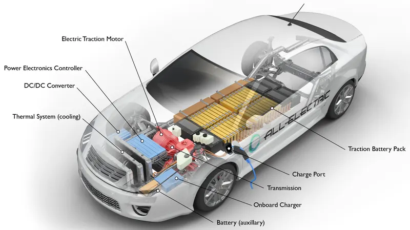
The main components used in an electric vehicle are:
- Battery
- Electric traction motor
- Power electronic controller
- Motor controller
- Transmission system
- Vehicle body
The block diagram of an electric vehicle:
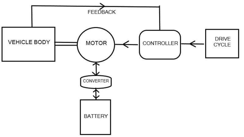
- The block diagram of the electric vehicle gives the basic overview of the drivetrain of the vehicle.
- It is divided into four parts as: Vehicle body, Motor and Controller part, Drive input, battery.
- In vehicle body we used gear box, tires and differential and inertia.
- In the motor and motor controller part, we used simple DC motor, H bridge for its control, PWM generator.
- In the Battery system, we used battery with controlled current source.
- In the drive cycle, various drive cycles are used for the study.
Mathematical modelling of electric vehicle in simulink:
The simulink model of the electric vehicle is shown below, we did simulation of the electric vehicle with various drive cycles using the powertrain blockset available in the simulink library. Various drive cycles are given as a input to the vehcile for the reference to the longitudinal driver and feedback speed is provided from the vehicle output. The longitudinal driver compares the two speed by using PI controller and gives acceleration and braking command to the motor controller block. Battery is used to provide power to the motor and vehicle body block shows the vehicle dynamics. The scopes are used to give the output signals.
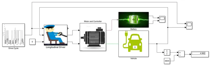
The block used for the modelling of an electric vehicle are:
- Drive Cycle Source block
- From Spreadsheet block
- Slider Gain
- Multi-Port Switch
- Longitudinal Driver
- DC motor
- H-Bridge
- Battery
- Controlled Current Source
- Controlled PWM Voltage
- Controlled Voltage Source
- Simple Gear
- Differential
- Inertia
- Magic Tire
- Vehicle Body
- PS Constant
- Solver Configuration
- Electrical Reference
- Current Sensor
- Inport
- Outport
- PMC_Port
- Mechanical Rotational Reference
- PS-Simulink Converter
- Simulink-PS Converter
- Integrator
- Product
- Gain
- Constant
- Divide
- Scope
- Display
System Level Configuration:
Subsystem of Vehicle:
Modelling of the vehicle body is done by using the block as shown in the below diagram.
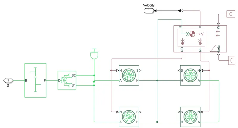
The above blocks are forming a subsystem which which represents the part of the whole vehicle. Four tires are connected, where the right two tires are the rear wheels and the remaining two are the front wheels. They are interconnected to the hub of the vehicle body block and their respective axle are connected accordingly. We connected the rear axle to the gear box as we have to make rear wheel drive vehicle. The wind velocity port and the grade angle port are connected to the physical constant block which are assigned the value of zero.
The blocks used are:
Vehicle Body:
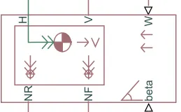
The blocks contains six ports which can be used to model various aspect of the vehicle body. The ports are mentioned below:
H - This represents the hub and is used to connect the hubs of wheels to the main body of the vehicle.
V - Physical signal output port which stands for velocity and gives the output velocity of the vehicle.
W - Physical signal input port and allow us to model a wind velocity that act against the vehicle.
NR - Physical signal output port use for connecting the rear wheel.
NF - Physical signal output port for connecting the front wheels of the vehicle.
Beta - Physical signal input port which allows the modelling of vehicle for hill climbing condition.
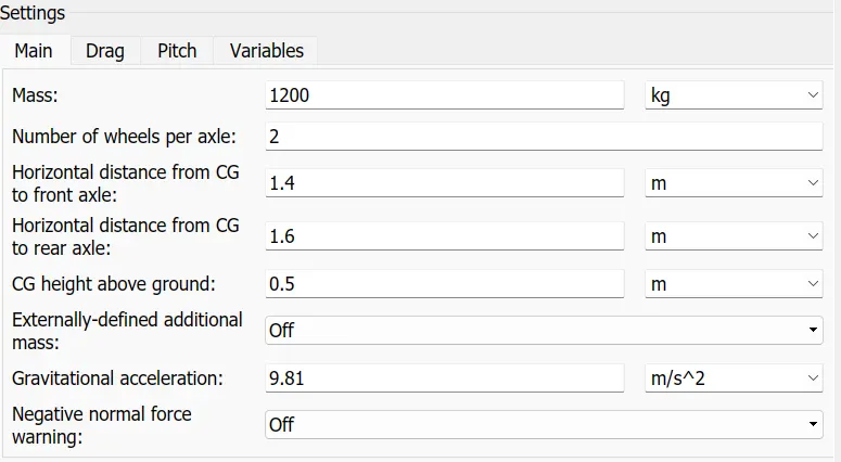
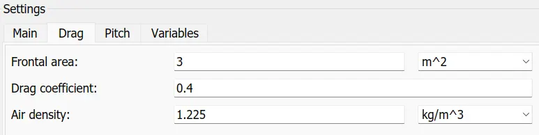
Model parameters use for vehicle body are:
Tire:
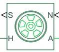
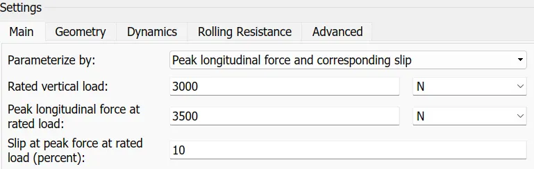
The tire block model a tire with friction parameterized in terms of static and kinetic coefficients. The static friction coefficients determines the applied torque at which the tire losses traction and begins to slip. The kinetic friction coefficients determines the amount of torque that the tire transmit to the pavement once it begins to slip. The tire regains traction once its relative velocity over the pavements falls below the traction velocity tolerance specified. To increase the fidelity of tire model, the block enables us to specify properties such as tire compliance, inertia and rolling resistance.
N - Input port which represents the normal force acting on the tire.
S - Physical signal output port that gives the tire slip
H - Mechanical translation port for the wheel hub
A - Mechanical rotational conserving port for the axle
The parameters set for the tire given below:

Simple Gear:
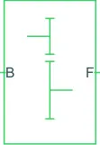
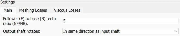
The block models a gear system with fixed gear ratio with non-inertia effect. However we can modify the messing of gear teeth. The follower to base ratio is set to 5 and the output shaft rotate in the same direction as the input shaft.
B (base) and F (follower) are rotational port that specifies the relation with the output shaft rotation.
Differential Block:

By using this block we add inertia and losses of gear machine and viscous gear machine. It represents the gear mechanism that allows the driven shaft to spin at different speed. Differentials are common in automobiles, where they enables the wheels to spin at different speeds.
S1 & S2 - Mechanical rotational port belonging to the two sun gears
D - Drive shaft
Inertia:

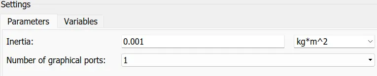
It represens the mechanical rotational inertia
Inertia value is set as default.
Subsystem of Motor and Controller:
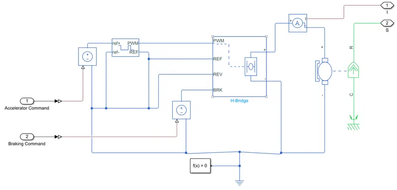
The above diagram represents the subsystem of the motor and motor controller part. Here DC motor is used for the propulsion power. The DC motor is controlled by the H-bridge pulse width modulated controller. The H bridge handles the operation of the motor in the motoring and the generating mode depending upon the input from the longitudinal driver. The controlled PWM voltage block is used to give the controlled pulse width modulated voltage signal to ht eH bridge.
DC motor:
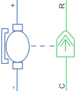
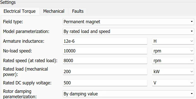
DC motor is used here because they are easy or modelling and have a very few parameters to run for a particular application. It has two parts one is mechanical and other is electrical part. The mechanical system has two ports as C and R. C port represents the casing and R port represents the rotor which gives torque. The electrical system has positive and negative terminals for applying the voltage. Port C is connected to the mechanical rotational reference as it is stationary and R is connected to the gear system of the vehicle.
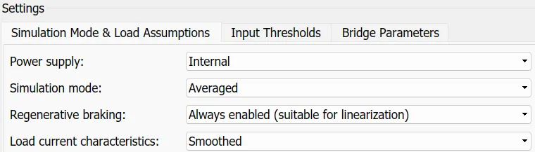
H-Bridge:
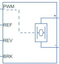
It is the H-bridge block used for controlling the motor that works as a motor controller. The H-bridge block output is controlled voltage waveform that depends upon the input signal at the at the PWM port.
Positive and negative port at the H terminal is used for further connection.
REF - Reference port
PWM - Input is applied to this port as a voltage
REV - Reverse port
BRK - Brake port
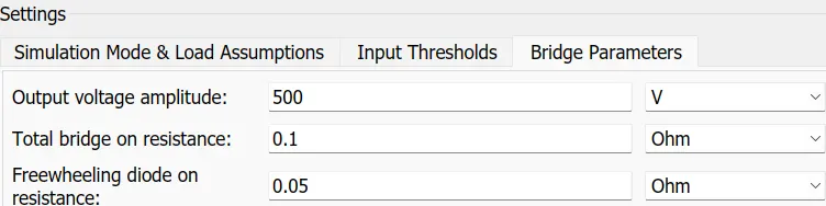
Controlled PWM Volage:
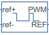
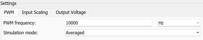
It represents the pulse width modulated voltage source.
Electrical input port - The block gives the duty cycle based on the reference voltage across its positive and negative ports.
REF - Floating zero reference port
PWM - Pulse width modulated signal is provided from this output port
Subsystem of Battery:
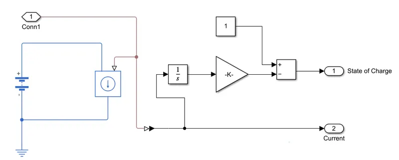
Here battery is used to supply the required power the DC motor. The current controlled source is used to provide reuired current from the battery for the entire simulation. In order to calculate the state of charge of the battery, the modelling is done. The current value from the battery is used for the SOC calculation. The current is first integrated which gives the charge in coulomb. Now from the current is converted into the Ah capacity and it will substracted from the value of one which gives the state of charge of the battery.
Battery:

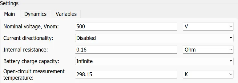
This block is used to power the DC motor for the simulation. The ratings of the battery are calculated by based on the motor requirement.
The parameter used for the battery are as follow:
Subsystem of Drive cycle:
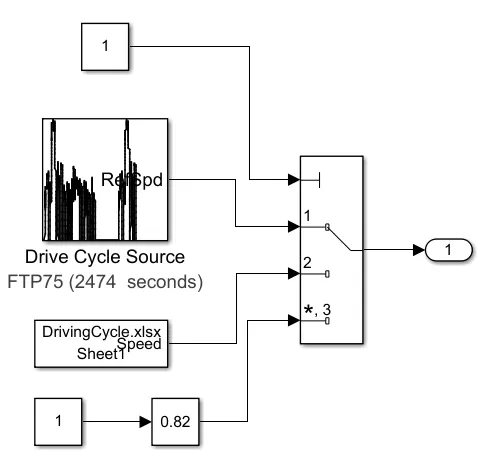
In the above subsystem multi port switch is used to give the multiple reference input to the vehicle. Depending upon the value given at the port one it will give the required input to the system. Here various methods are used to give input to the vehicle. This are drive cycle source, from spreadsheet and the slider gain.
Drive Cycle Source:
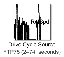
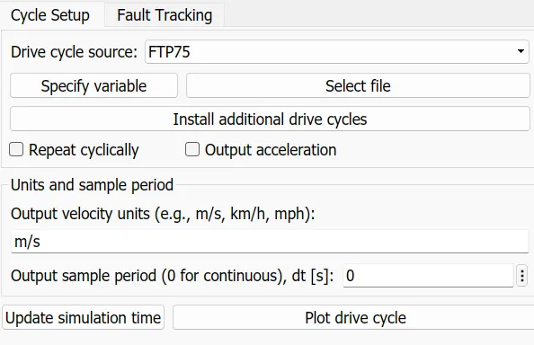
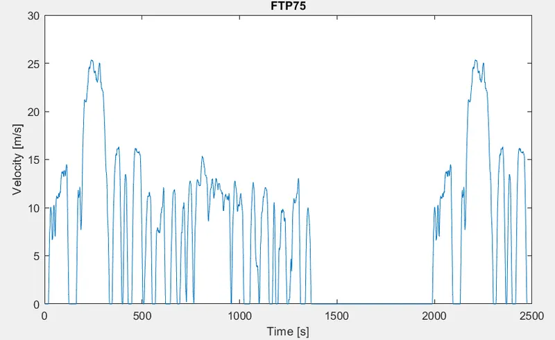
This block is used to give the input reference signal to the vehicle. It is used defined having few drive cycles for the simulation. We use FTP75 drive cycle for the simulation having the time period of 2474 seconds and maximum speed of upto 25 m/s.
The figure below shows the TP75 drive cycle.
Results:
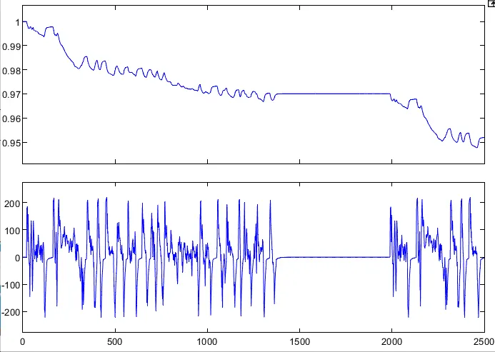
- The first waveform shows the state of charge of the battery during the entire simulation time.
- This shows that state of charge of the battery is decreases from 100 % to the 95 %.
- The waveform is going up for very few time, it shows that there is a charging of battery happening due to the regenerative braking.
- The second waveform shows the battery current.
- This positive and negative going waveforms shows the current during motoring and braking mode.
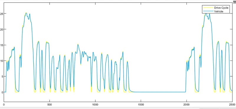
- Above waveform shows the actual vehicle speed and the reference speed from the drive cycle source.
- This two waveforms overlapping with each other that shows that the vehicle is following the drive cycle reference speed.
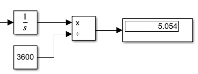
- The above diagram shows the distance travelled by the vehicle during the entire simulation.
- The vehicle is travelled a distance of 5.054 Km in the entire journey.