Final Project: Design of an Electric Vehicle
ELECTRIC VEHICLE – MODELLING AND SIMULATIONS
The Electric Vehicle developed by the motor, battery, controller, converters, and wheels.
The motor connected to the differential of the wheels.
In this basic configuration of EV, the four wheels are used. Two wheels are connected in the front portion called front wheel drive.
Rest of two wheels connected at the rear portion of the drive, so it is called real wheel drive.
Both the ends wheels are connected through the differential.
The differential is provided the balancing to the rear and front wheel drive system.
The differential portion represents a gear mechanism that allows the driven shaft to spin at different speeds.
The fidelity of the gear model improved by specifying the parameters of the differential gear system like gear inertia, meshing, and viscous losses.
A battery pack is used as the source of the electric vehicle model.
A lithium-ion battery fixed in the modeling of Electric Vehicle (EV) which provides input supply both the motors connected across the front and rear end of the model.
- Modeling of Electrical Vehicle (EV)
We developed a four-wheel drive model of an electric vehicle.
Two wheels place at the front portion and the other two placed at the rear portion. Both real and front wheels are controlled by an induction motor and synchronous motor with the help of the inverter controller circuit.
The vehicle body placed on the four wheels of the drive with initial parameters of environments like wind, inclined and throttle.
Before performing the modeling of the four-wheel electric vehicle drive train, we finalize the parameters and behavior of the vehicle body.
On the front wheel side, we used a synchronous motor with a controller connected to the battery voltage source.
Inverter circuit applied in the controller to provide a sufficient amount of electric supply to the motors.
Vehicle Longitudinal Dynamics For the evaluation of longitudinal nature of electric vehicles some equations are used.
The Electric vehicle model based on motion resistance forces like an aerodynamic drag, rolling and climbing resistance and vehicle velocity.
The rolling resistance ( is that term which related to the energy losses due to tire deformation and adhesion of contact area
- Vehicle Longitudinal Dynamics
For the evaluation of longitudinal nature of electric vehicles some equations are used.
The Electric vehicle model based on motion resistance forces like an aerodynamic drag, rolling and climbing resistance and vehicle velocity.
The rolling resistance ( is that term which related to the energy losses due to tire deformation and adhesion of contact area.
Simulation of Electric Vehicle with Simulink
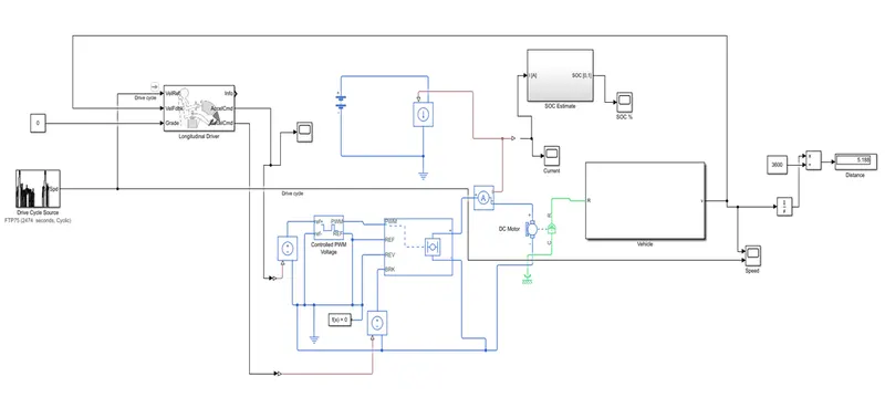
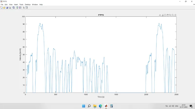
Using FTP 75 as Drive Cycle Source – This drive cycle is used to perform the simulation with simulation time of 2274 seconds.
|
Simulink blocks |
functions |
|
Drive cycle |
For input of vehicle driver |
|
Longitudinal driver |
For driving acceleration & deceleration comand |
|
Pwm voltage controller |
To generate controlled pwm voltage |
|
H-bridge |
To supply controlled power to motor |
|
DC – motor |
For rotation of wheel |
|
Vehicle |
|
|
Battery |
Supply for components |
|
Display |
To show output value |
|
Scope |
To show graph of output |
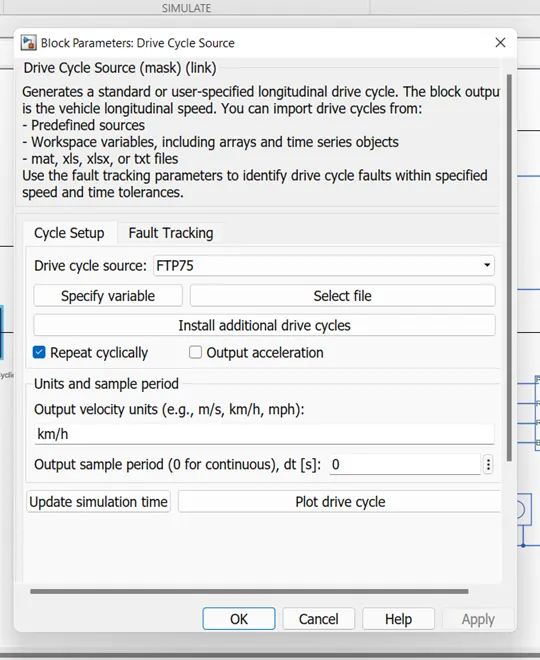
Drive cycle sourse:
Generates a standard or user-specified longitudinal drive cycle. The block output is the vehicle longitudinal speed. You can import drive cycles from:
- Predefined sources
- Workspace variables, including arrays and time series objects
- mat, xls, xlsx, or txt files
Use the fault tracking parameters to identify drive cycle faults within specified speed and time tolerances.
Drive cycle plot FTP75:
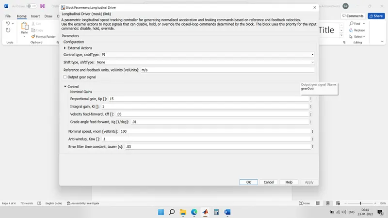
LONGITUDINAL DRIVER:
A parametric longitudinal speed tracking controller for generating normalized acceleration and braking commands based on reference and feedback velocities.
Use the external actions to input signals that can disable, hold, or override the closed-loop commands determined by the block. The block uses this priority for the input commands: disable, hold, override.
CONTROLLED PWM VOLTAGE:
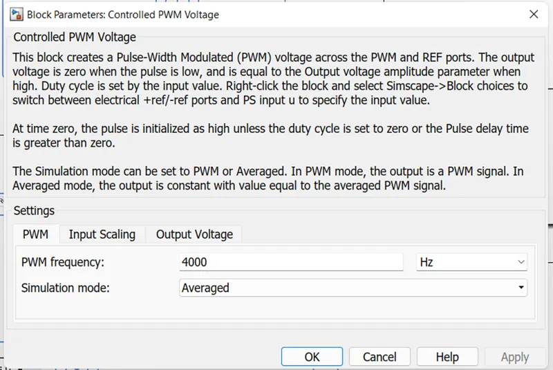
This block creates a Pulse-Width Modulated (PWM) voltage across the PWM and REF ports. The output voltage is zero when the pulse is low, and is equal to the Output voltage amplitude parameter when high. Duty cycle is set by the input value. Right-click the block and select Simscape->Block choices to switch between electrical +ref/-ref ports and PS input u to specify the input value.
At time zero, the pulse is initialized as high unless the duty cycle is set to zero or the Pulse delay time is greater than zero.
The Simulation mode can be set to PWM or Averaged. In PWM mode, the output is a PWM signal. In Averaged mode, the output is constant with value equal to the averaged PWM signal.
H-BRIDGE:
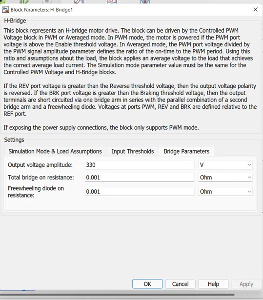
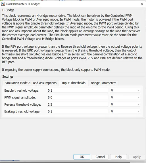
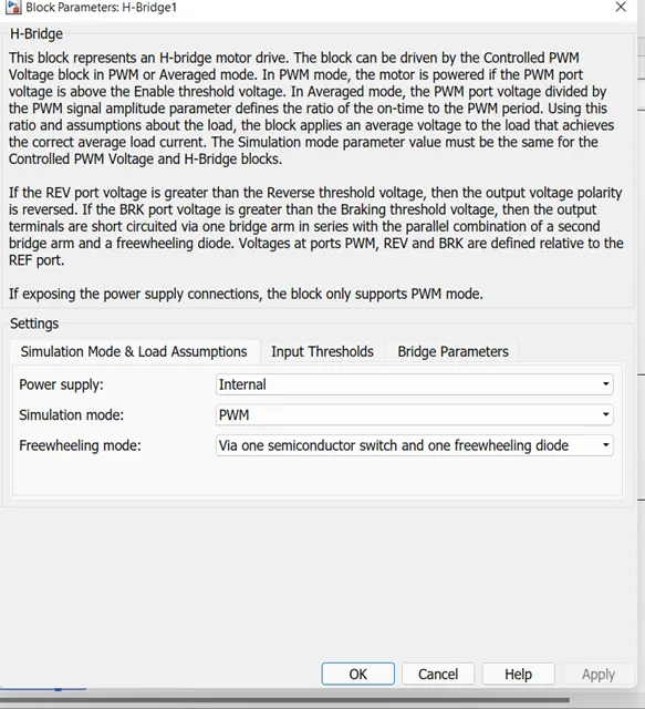
This block represents an H-bridge motor drive.
The block can be driven by the Controlled PWM Voltage block in PWM or Averaged mode. In PWM mode, the motor is powered if the PWM port voltage is above the Enable threshold voltage.
In Averaged mode, the PWM port voltage divided by the PWM signal amplitude parameter defines the ratio of the on-time to the PWM period.
Using this ratio and assumptions about the load, the block applies an average voltage to the load that achieves the correct average load current.
The Simulation mode parameter value must be the same for the Controlled PWM Voltage and H-Bridge blocks.
If the REV port voltage is greater than the Reverse threshold voltage, then the output voltage polarity is reversed.
If the BRK port voltage is greater than the Braking threshold voltage, then the output terminals are short circuited via one bridge arm in series with the parallel combination of a second bridge arm and a freewheeling diode.
Voltages at ports PWM, REV and BRK are defined relative to the REF port.
If exposing the power supply connections, the block only supports PWM mode.
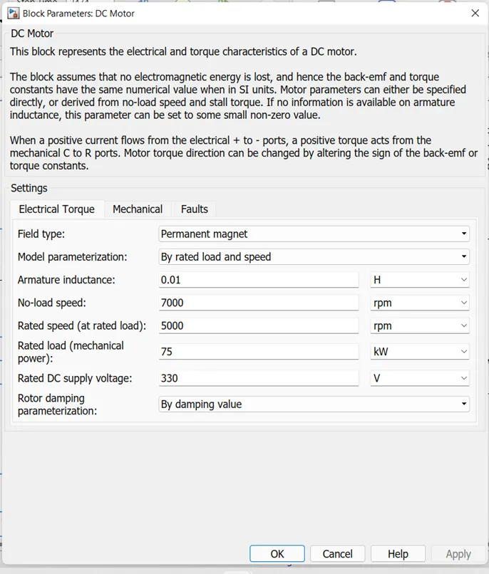
DC-MOTOR:
This block represents the electrical and torque characteristics of a DC motor.
The block assumes that no electromagnetic energy is lost, and hence the back-emf and torque constants have the same numerical value when in SI units. Motor parameters can either be specified directly, or derived from no-load speed and stall torque.
If no information is available on armature inductance, this parameter can be set to some small non-zero value.
When a positive current flows from the electrical + to - ports, a positive torque acts from the mechanical C to R ports. Motor torque direction can be changed by altering the sign of the back-emf or torque constants.
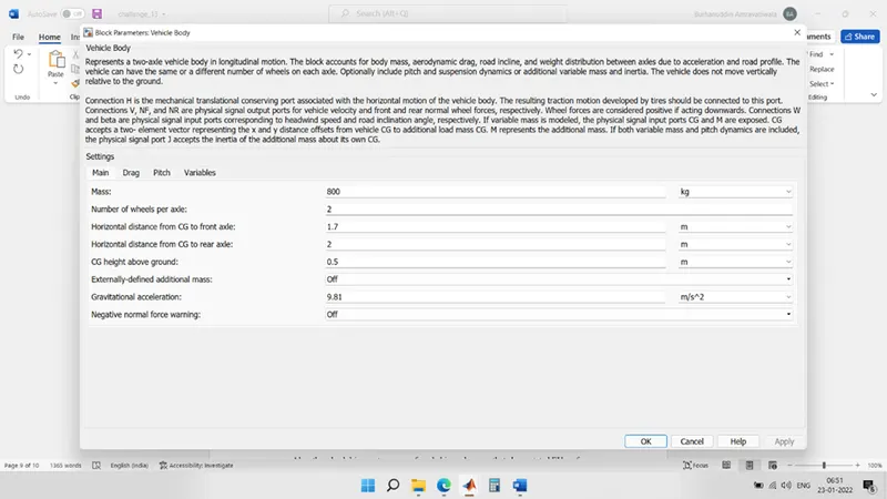
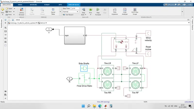
VEHICLE BODY:
Represents a two-axle vehicle body in longitudinal motion.
The block accounts for body mass, aerodynamic drag, road incline, and weight distribution between axles due to acceleration and road profile.
The vehicle can have the same or a different number of wheels on each axle.
Optionally include pitch and suspension dynamics or additional variable mass and inertia. The vehicle does not move vertically relative to the ground.
Connection H is the mechanical translational conserving port associated with the horizontal motion of the vehicle body.
The resulting traction motion developed by tires should be connected to this port. Connections V, NF, and NR are physical signal output ports for vehicle velocity and front and rear normal wheel forces, respectively.
Wheel forces are considered positive if acting downwards. Connections W and beta are physical signal input ports corresponding to headwind speed and road inclination angle, respectively. I
f variable mass is modelled, the physical signal input ports CG and M are exposed. CG accepts a two- element vector representing the x and y distance offsets from vehicle CG to additional load mass CG. M represents the additional mass.
If both variable mass and pitch dynamics are included, the physical signal port J accepts the inertia of the additional mass about its own CG.
BATTERY:
This block models a battery.
If you select Infinite for the Battery charge capacity parameter, the block models the battery as a series internal resistance and a constant voltage source.
If you select Finite for the Battery charge capacity parameter, the block models the battery as a series internal resistance plus a charge-dependent voltage source defined by:
V = Vnom*SOC/(1-beta*(1-SOC))
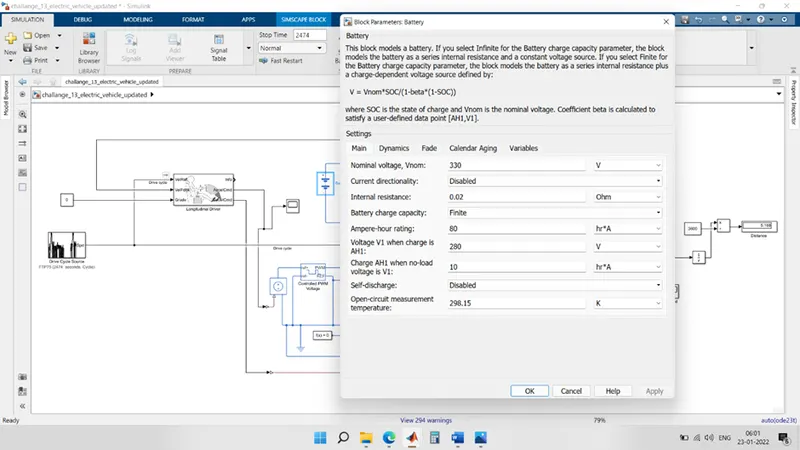
where SOC is the state of charge and Vnom is the nominal voltage.
Coefficient beta is calculated to satisfy a user-defined data point [AH1,V1].
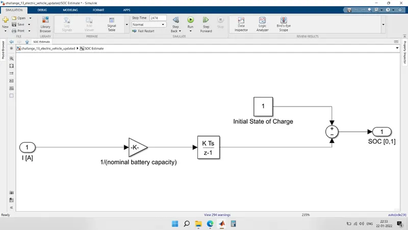
SOC ESTIMATOR CIRCUIT:
RESULT:
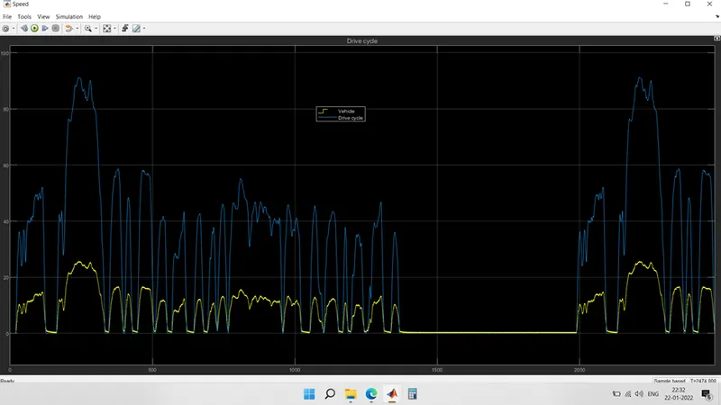
VEHICLE SPEED:
The reference speed value & feedback value of drive cycle is plotted.
We have taken drive cycle ftp75, according to that drive cycle reference the velocity command is plotted .
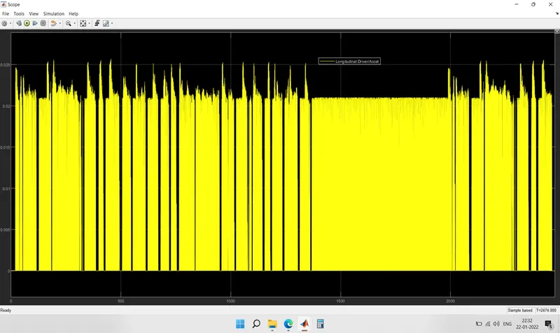
ACCELERATION COMMAND FROM DRIVE CYCLE:
From the acceleration command of drive cycle, the graph is plotted.
Here throttle input form longitudinal driver model block is taken.
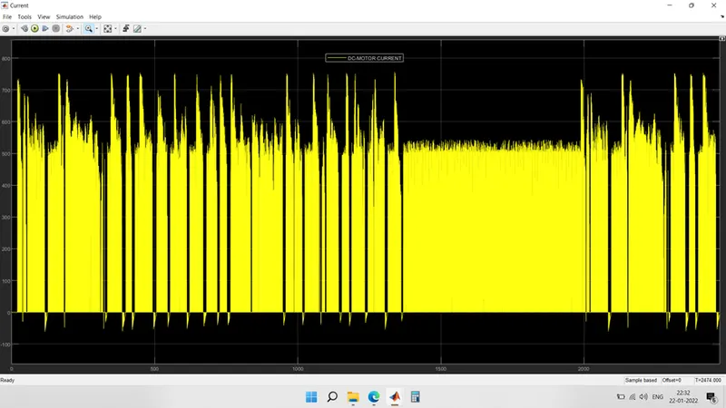
DC-MOTOR LOAD CURRENT:
Now, as the throttle input is given, the dc motor will give machinal output, with reference to electrical input supply.
To generate some RPM, it will require current according to load.
The same current drawn by motor graph is plotted.
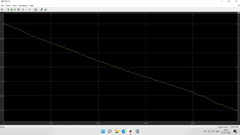
SOC %:
As we know, the main power source is battery for motor.
Battery provides necessary power required by motor at every stage of propulsion.
Now according to usage of battery, its state of charge is decreased.
That decrease in SOC is plotted.
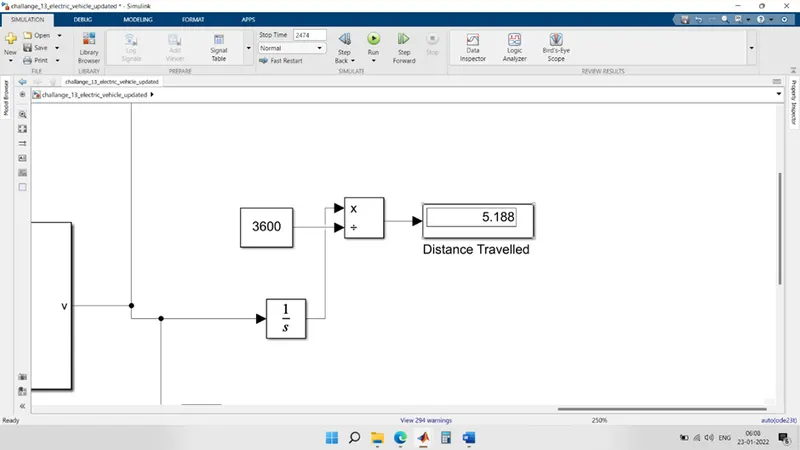
DISTANCE TRAVELLED:
5.188 km
Using the basic formula of distance and velocity , we have integration of velocity and obtained the total distance travelled in 2474 seconds.
Conclusion:
Proposed EV wheel drive system which is having individual front and rear control, improves the EV performance such as torque and speed stability, steer ability, drivability, and safety at low speed and high-speed operations.
Also, the wheel drive systems were founded in such a way that above stated EV performance requirements attained more efficiently.
The drive systems are also successfully synchronized in such a way that, if in some adverse conditions torque generated from the front wheel drive is found insufficient to drive the EV at desired speeds at the same time rear wheel drive system provides the adequate torque to the EV.