Final Project: Design of an Electric Vehicle
TITLE:- Final Project for Design of an Electric Vehicle.
AIM:- To Create a model of electric car which uses a battery and a DC motor using MATLAB software and Choose suitable blocks from Powertrain block set.
OBJECTIVE:-
- To make a most Simple and Low run time Vehicle model using individual component block.
- To Change of model parametrs.
- To check out performance parameters like Speed, State Of Charges(SOC), Current etc with Various Drive Cycle.
- To play with:- Motor power , Vehicle body (Mass of Vehicle, Rolling Resistnsce (Frr), Aerodynamic force(Fad).
- To show the Output Result from Various Drive Cycle input as like- Signal Builder and FTP75.
- To Write down Conclusion Electric Vehicle(EV) Model.
THEORY:-
The Electrical Vehicle (EVs) is a Vehicle that runs on electricity alone.Such a Vehicle does not contain an Internal Combustion Engine (IC engine).like the other conventional vehicle.It an electric motor to run the vehicle. It type of motor used like Bushless or Permanent magnet DC motor in Vehicle.These vehicle are becoming very popular now day.The types of electric car batteries are also depends on the car system. The most popular electric car battery used is lithium-ion.Li-on batteries have a very high power to weight ratio. This type of electric car battery is high energy efficiency. Performance at high temperatures is also good. The battery has a greater energy ratio per weight – a parameter that is very important for electric car batteries. The smaller the battery weight (same kWH capacity) means the car can travel further with a single charge.This battery also has a low “self-discharge” level, so the battery is better than any other battery in maintaining its ability to hold its full charge.
Electric vehicles (EVs) are a promising technology for achieving a sustainable transport sector in the future, due to their very low to zero-carbon emissions, low noise, and high efficiency. Nonetheless, the large penetration of EVs is expected to affect the existing power grids, due to high loads. Uncontrolled charging of plug-in electric vehicles represents a challenge for the energy system.
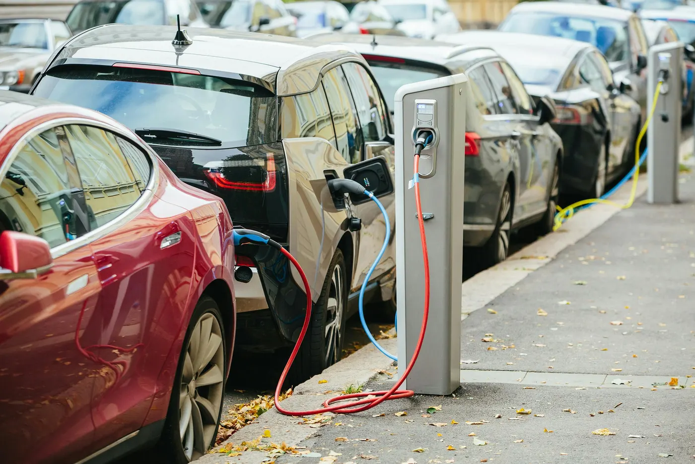
Fig:- Charging Station In Smart City For Electrics Vehicles (EVs)
The controlled charging of EVs—within the concept of smart city—can have a significant impact on the power grid load, voltage, frequency, and power losses. In this direction, smart charging has been proposed, in order to avoid grid congestion and to integrate renewable energy. This chapter elaborates the transition to a new age of mobility and the challenges of charging mechanisms within the concept of the smart city. This chapter reviews the concept, framework, advantages, challenges, and optimization strategies to vehicle-to-grid. Brief reviews of different strategies, smart charging schemes, and relative benefits are also presented. Some case studies are also employed in order to throw light at successful practices and potential barriers in regards the end-user’s motivation to use such smart charging systems.
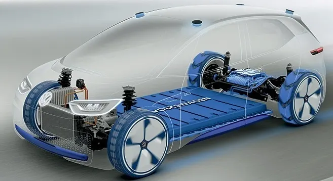
Fig:- Electric Vehicle Car
How does Elecrical Vehicle(EVs) run as shown in below:-
When pedal of the car is pressed, then the Controller takes and regulates electrical energy from batteries and inverters and With the controller set, the inverter then sends a certain amount of electrical energy to the motor. Then the an Electric motor converts electrical energy into mechanical rotational energy.Its Rotation of the motor rotor rotates the transmission so the wheels turn and then the car moves.
There are Two types of Electrical Vehicle(EVs) as show in following:-
- Battery Electric Vehicle (BEVs) or Pure Elecric Vehicle(PEVs)
- Plug-in Hybrid Electric Vehicle (PHEV).
Main components of an Electri Vehicle(EVs) as shown in below:-
- Electric Battery
- Inverter
- Electric Motor
- Power Control Unit
- DC/DC converter
- Regenerative Braking System
- Charge port
1] Electric Battery:-
Battery stored the electricity required to run the vehicle.The battery supplies electric current to the motor and thus, the vehicle runs.the higher the capacity of the battery the higher is the vehicle.The Most modern electric vehicle use Lithium-iron type battery. These batteries have higher energy density.It mens they are capable of storing more energy.
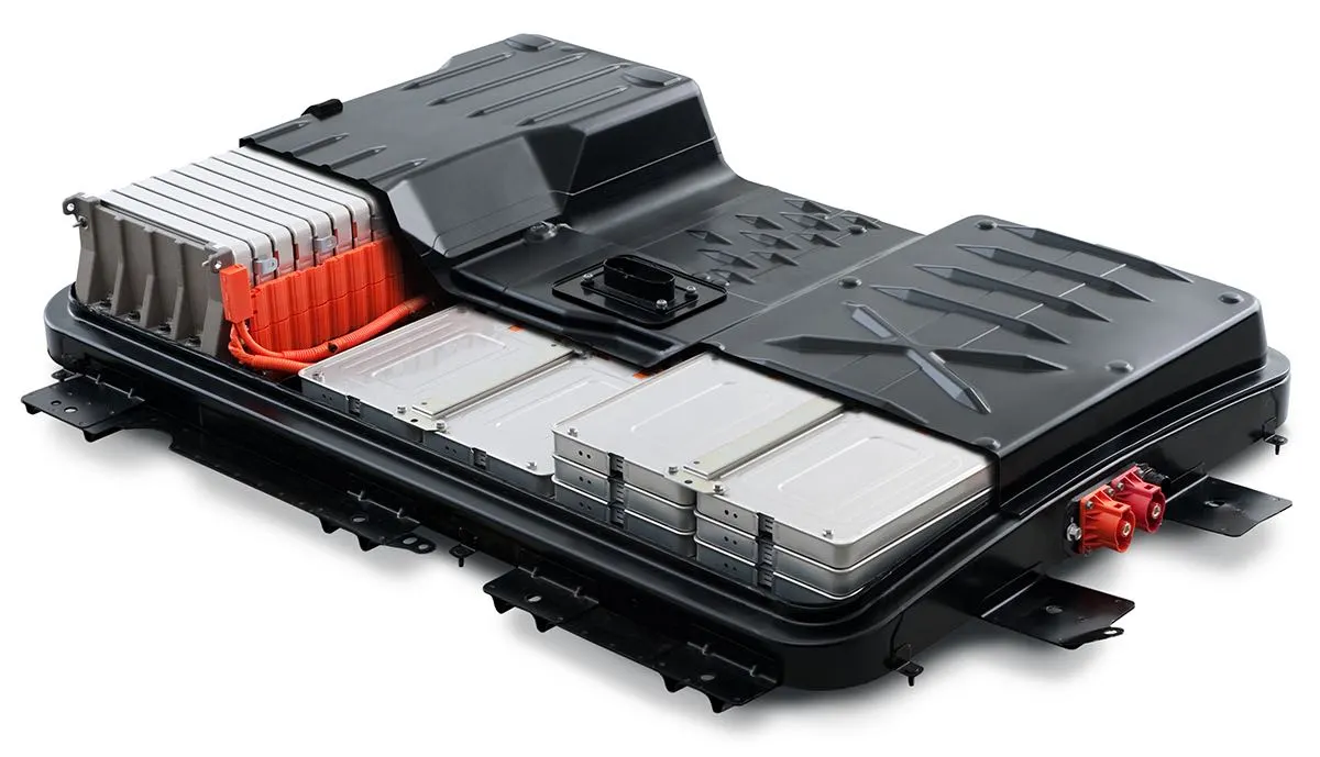
2] Inverter:-
The Battery stored the electric current in the form of direct current(DC). But the majority of the motors used in the electric vehicle run on Alternating Current(AC), So the inverter performs the function of converting DC to AC.
3] Electric Motor:-
An electric motor provided the power to rotate the wheel.Motors may be of DC/AC type. However,the AC motors are more common.
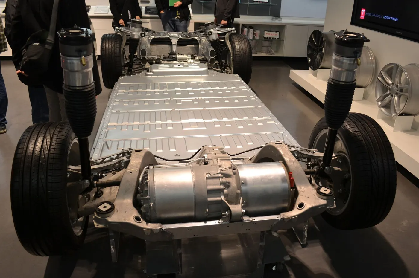
4] Power Control Unit:-
The control unit performs the main task.It controls the the activities of all the components of an electric vehicle.It monitors the output of the motor.charging of batteries, Also it provided the necessary information of the driver.
5] DC/DC converter:-
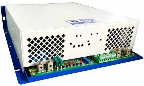
This device converts higher voltages DC power form the traction battery pack to the lower voltages DC power needed to run vehicle accessories and recharge the auxiliary battery.
6] Regenerative Braking:-
The electric vehicle has only limited energy available.Hence,you need to save energy bit of it.This system recovers the energy lost in braking the vehicle and utilizes it to charge the batteries.
7] Charge port:-
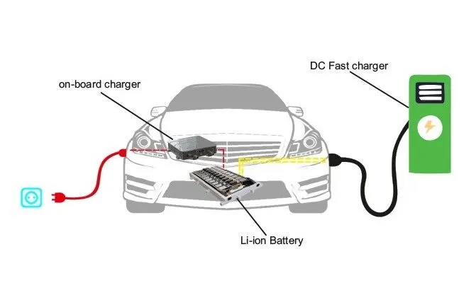
The charge port allow the vehicle to conect to an external power supply in order to charge the traction battery pack.
Advantages of using an Electric Vehicle:-
1] Less air pollution:- There is an absence of any combustion process, Hence,these vehicle do not emit polluting gases into the atmosphere.
2] Less noise pollution:- The electric motor runs quietly.Hence,the noise level while operating these vehicle is much lower than that of the petrol or diesel engine powered cars.
3] Higher Efficiency:- The efficiency of operation of an electric vehicle is much higher. For EV the efficiency of an electric motor is nearly 90% compared to an internal combustion engine.
disadvantages of using an Electric Vehicle:-
1] High price:- The production of an electric vehicle is not yet done completely on a commercial basis.Hence, vehicle are costly than conventional cars running on petrol or Diesel car.
2] Low range:- Range of an Electric vehicle is the distance that it can cover on a sigle charge.
Design model of Electric Vehcile(EV):-
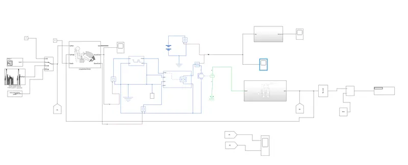
We have used Simulink block as shown in following:-
- Vehicle Body
- Tire (Magic formula)
- Simple Gear Block
- SOC Estimate Block
- DC motor( Permanent magnet DC motor)
- Battery
- H-Bridge Block
- Controlled PWM Voltage
- Longitudinal Driver
- Multiport Switch
- Signal Builder
- Drive Cycle Sorce FTP75
- From Spreadsheet
- Controlled Voltage Source
- Controlled Current Source
- Current Sensor
- Simulink P-S Converter
- P-S Simulink Converter
- Mechanical Rotational Reference
- Electrical Reference
- Scope
- Display Block
System level configurations and Model parameters:-
Block Explaination and Its Parameters:-
1] Vehicle Body:-
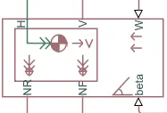
In this block there are total 6 ports.The ports are mentioned following:-
NR port:- The physical signal output port to connect the rear wheel of vehicle.
NF port:- The physical signal output port to connect the front wheel of vehicle.
H port:- H stand for Hub. It is used to connect the to the main body of vehicle.
V port:- V stand for velocity. It is used output the velocity of the vehicle.
W poert:- W shand for wind velocity.
beta port:- It the vehicle to indergo an Inclination of hill climbing force.
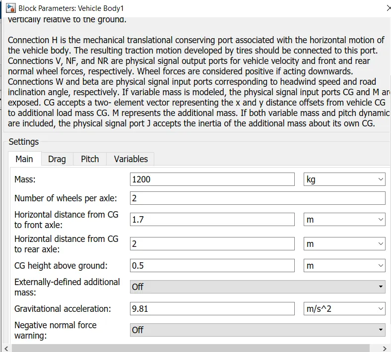
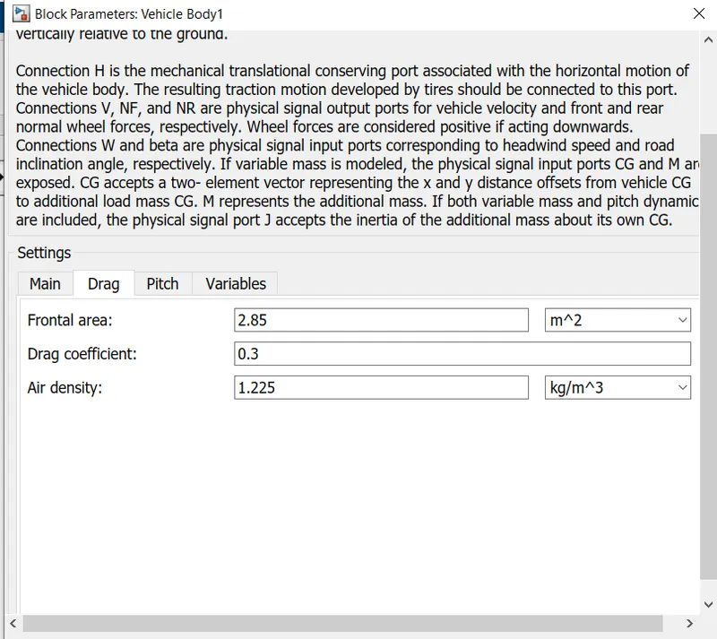
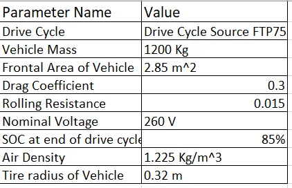
In this bock we have change parameter mass of vehicle=1200 kg, Frontal area=2.85m^2,Drag coefficient=0.3 and Air density=1.225 kg/m^2.
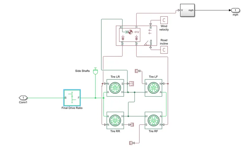
Subsystem in Vehicle Body:-
2] Tire (Magic Formula):-
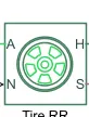
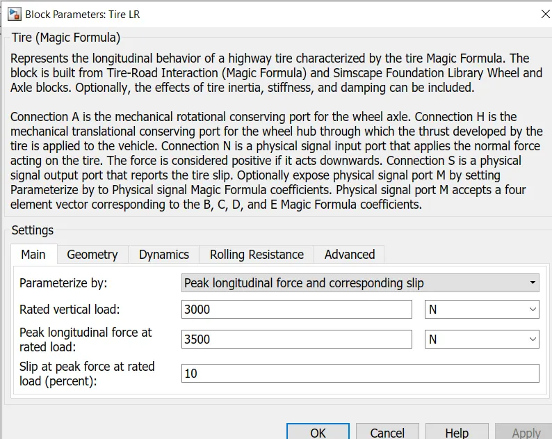
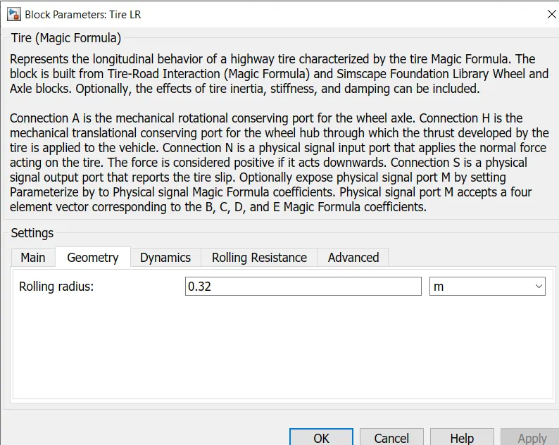
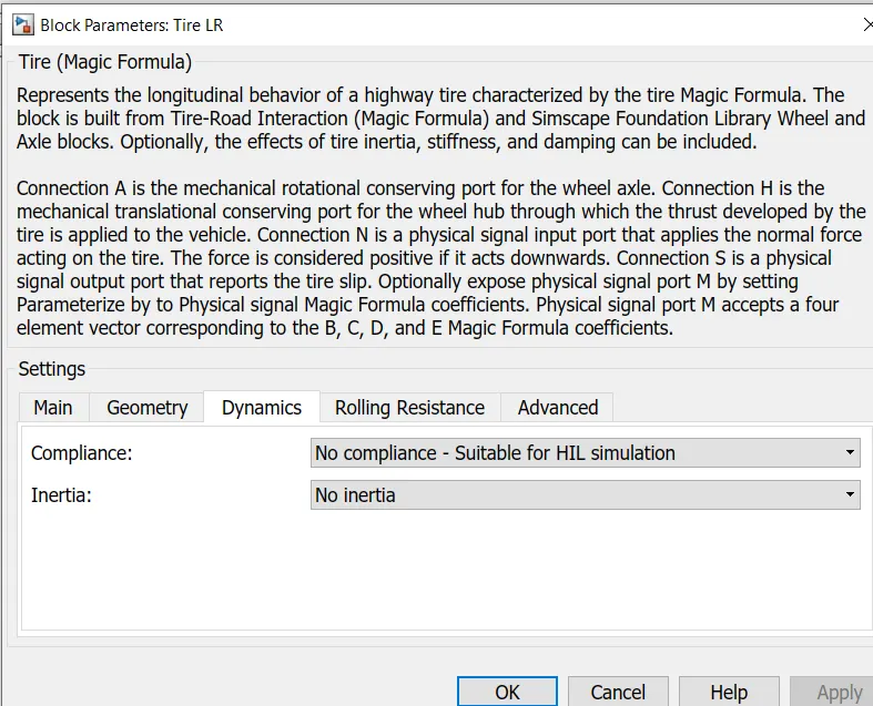
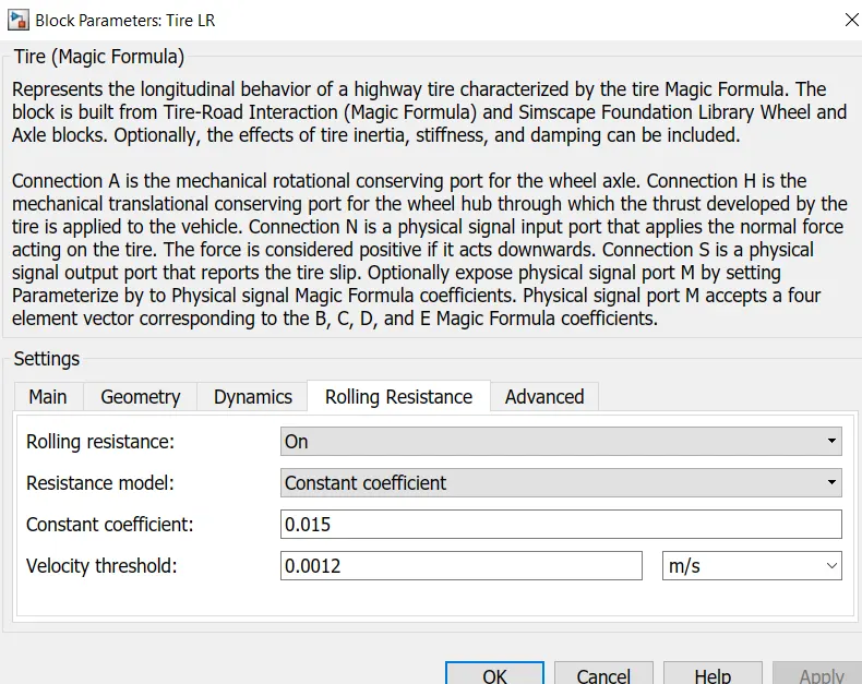
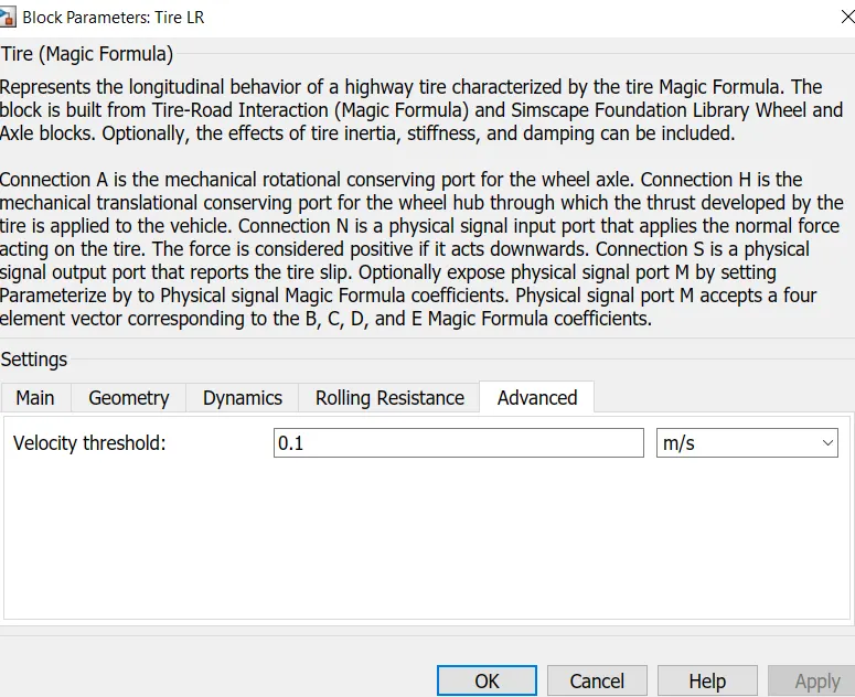
The tire represents the longitudinal behavior of a highway tire characterized by the tire Magic Formula. The block is built from Tire-Road Interaction (Magic Formula) and Simscape Foundation Library Wheel and Axle blocks. Optionally, the effects of tire inertia, stiffness, and damping can be included. In this there are 4 port name as A,N,S,H. A port is conected the mechanical rotational conserving port for the wheel axle.H port is conected the mechanical translational conserving port for the wheel hub. N port is conected a physical signal input port that applies the normal force acting on the tire and S port is conected a physical signal output port that reports the tire slip.
3] Simple Gear Block:-
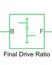
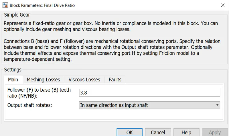
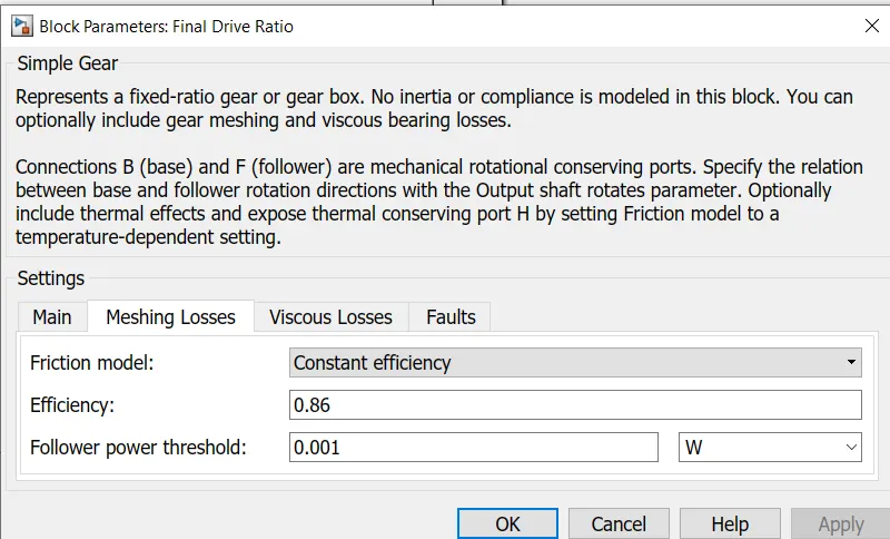
This block Represents a fixed-ratio gear or gear box. No inertia is modeled in this block. You can optionally include gear meshing and viscous bearing losses. In this block two port B port and F port. B stand for Base and F stand for follower. This port are mechanical rotational conserving ports.
4] DC Motor:-
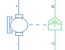
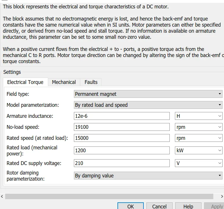
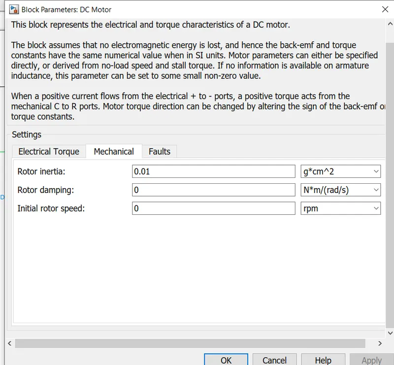
This block represents the electrical and torque characteristics of a DC motor. We have used permanent magnet DC motor. there are two side of in this block. The mechanical side is on the right and Electrical side is on the left. In mechanical side there are two port name as C and R port.C stand for Casing and R shand for rotor which is produce torque.The electrical side has a Positive and Negative terminal port for the voltage to be applied.When a positive current flows from the electrical + to - ports, a positive torque acts from the mechanical C to R ports. Motor torque direction can be changed by altering the sign of the back-emf or torque constants.
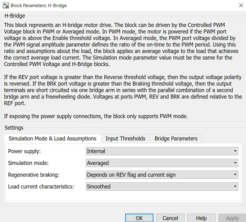
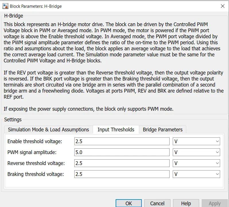
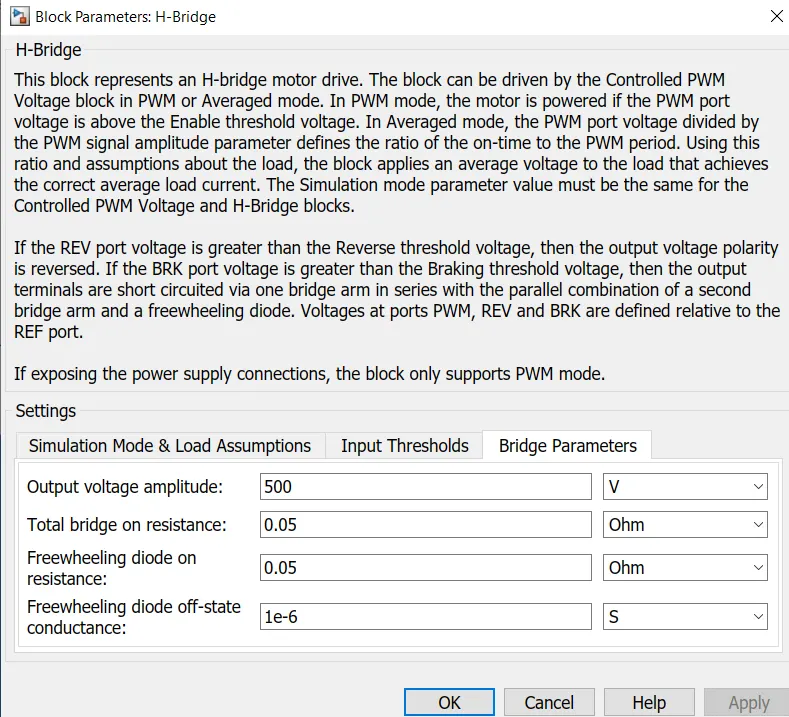
5] H-Bridge Block:-
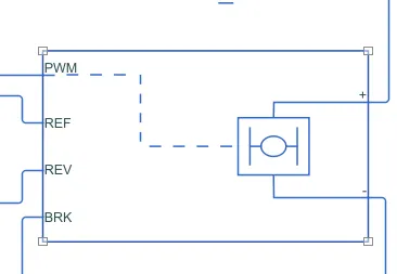
In this block there 4 port left side are mentioned following:-
1] PWM
2] REF
3] REV
4] BRK
This is a power converter which is needed to provide power of correct from and magnitude from the component to other. The power converter is needed to provide a DC voltage from the battery of the Electric Vehicle to the DC motor.
6] Controlled PWM Voltage:-
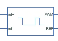
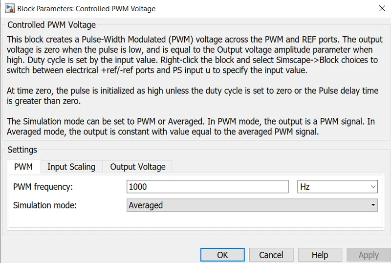
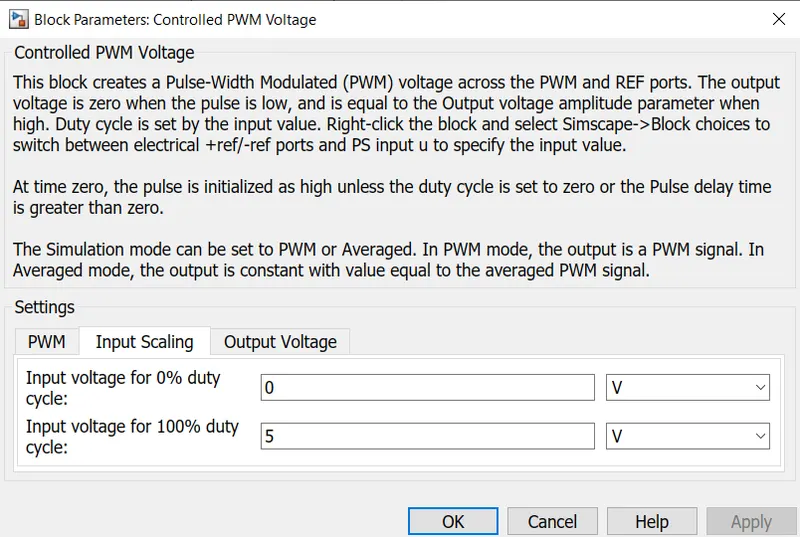
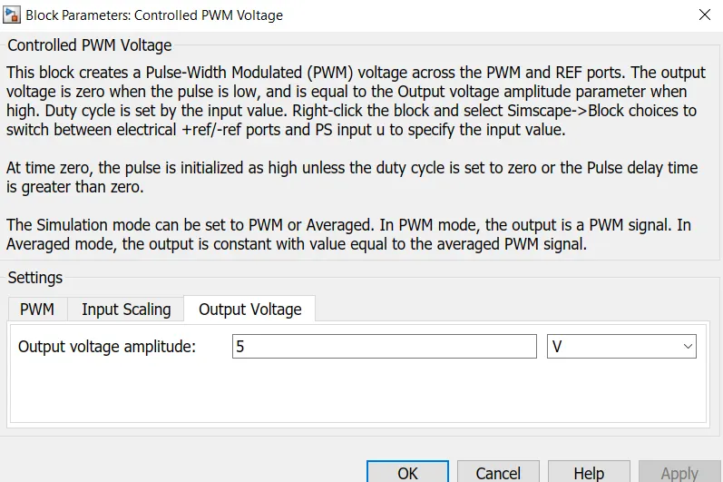
In this block there are 4 ports name as PWM,REF,ref positive,ref negative.This block creates a Pulse-Width Modulated (PWM) voltage across the PWM and REF ports. The output voltage is zero when the pulse is low, and is equal to the Output voltage amplitude parameter when high. Duty cycle is set by the input value.The Simulation mode can be set to PWM or Averaged. In PWM mode, the output is a PWM signal. In Averaged mode, the output is constant with value equal to the averaged PWM signal.
7] Lonaitudinal Driver:-
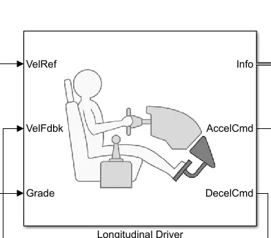
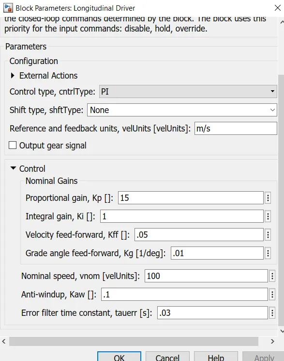
The this block is used for giving normalized acceleration and deacceleration command to controller on two set of data.In this block there are total Six ports. The first data is the reference velocity(VelRef), The Second data is the feedback velocity(VelFedbk), Grade port provides the a inclination angle on which the is vehicle is travelling in degree.Acceleration command port(AccelCmd) This port provide the acceleration command to a controlled voltage source. Deacceleration command(DecelCmd) this port provide the deacceleration command to another voltage source.
8] Multiport Switch:-
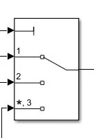
This block has a left side multi port input signal and one output port signal.the input signals corresponding to the truncated value of the first input. The inputs are numbered top to bottom (or left to right). The first input port is the control port. The other input ports are data ports.
9] Signal Builder:-
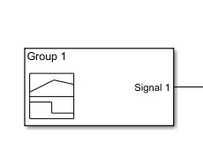
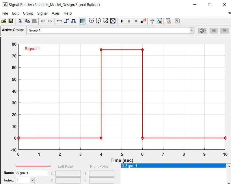
This block is used to create build for signal input.
10] Drive Cycle Source:-
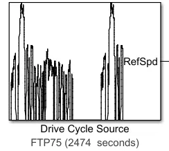
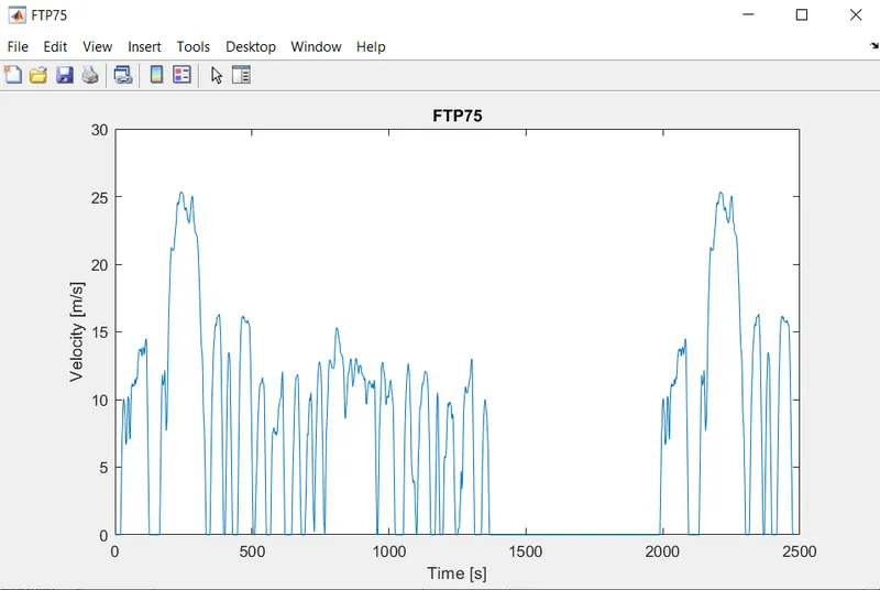
The Drive Cycle Source block generates a standard or user-specified longitudinal drive cycle. Drive cycles from predefined sources. By default, the block includes the FTP–75 drive cycle.The block output is the specified vehicle longitudinal speed, which you can use to::-
1) Predict the engine torque and fuel consumption that a vehicle requires to achieve desired speed and acceleration for a given gear shift reference.
2) Produce realistic velocity and shift references for closed loop acceleration and braking commands for vehicle control and plant models.
3) Study, tune, and optimize vehicle control, system performance, and system robustness over multiple drive cycles.
4) Identify the faults within tolerances specified by standardized tests, including:-EPA dynamometer driving schedules and Worldwide Harmonised Light Vehicle Test Procedure (WLTP) laboratory tests.
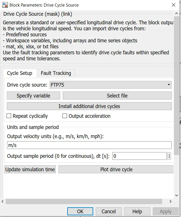
11] Battery Block:- This block models a battery. It generate a voltage source which help in supply electrical power to solenoide block.The battery will be the energy store of the Electric vehicle(EV).
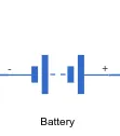
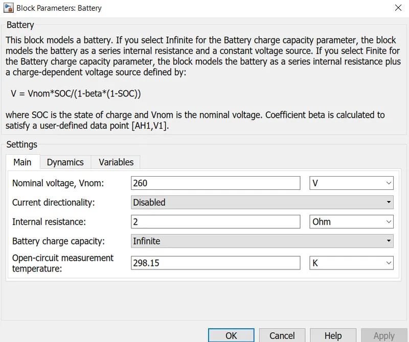
In this block we have set Nominal Voltage to 260 V and Internal resistance has been set to 2 Ohm.
12] Current Sensor Block:-
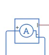
This block represents an ideal current sensor. It used a device that converts current measured in any electrical branch into a physical signal proportional to the current.In this block there are three port. The current in the battery circuit and the DC motor.in this block two terminal port name as Positive and Negative terminal across which the current sensor is inserted in to the circuit.The 3rd port output the physical signal.
13] Controlled Current Source:-

This block represents an ideal current source that is powerful enough to maintain the specified current through it regardless of the voltage across it. The output current is I = Is, where Is is the numerical value presented at the physical signal port.
14] Controlled Voltage Source:-

This block represents an ideal voltage source that is powerful enough to maintain the specified voltage at its output regardless of the current passing through it. The output voltage is V = Vs, where Vs is the numerical value presented at the physical signal port.
15] SOC Estimate:-
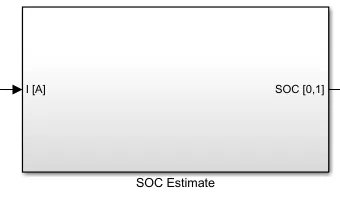
Subsystem in SOC Estimate block:-
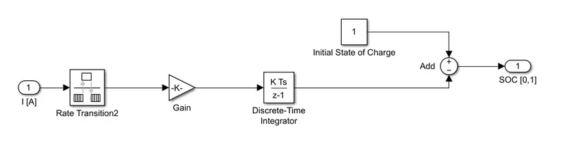
In this Subsystem was created of various block.To measure the SOC of the battery.The first block name as Rate Transition2. This block transfers data from the output of a block operating at one rate to the input of a block operating at a different rate. Use the block parameters to trade data integrity.We have used second port name as Gain Block.This block is used in order to multiplayer divide the signal coming from Rate Transition2 block.
Block parameters of the Gain block as shown below:-
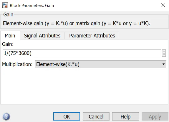
Next block used name as Discrete time Integrator.This block Use the Discrete-Time Integrator block in place of the Integrator block to create a purely discrete model. With the Discrete-Time Integrator block, you can:- 1] Define initial conditions on the block dialog box or as input to the block.2] Define an input gain (K) value.3]Output the block state.4]Define upper and lower limits on the integral.
We have used next block name as Sum Block. This block is used to perform addition and substraction operation as these block are made into a subsystem is called SOC Estimate.
16] Solver Configuration Block:- This block used for specifies the solver paramerter that your model needs before yopu can begin simulation.
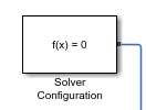
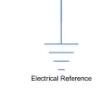
17] Electrical Referance:- The Electrical Referance block repesent an electrical ground. electrical port of the block are directly connected to ground.
18] Mechanical Rotational Reference:-
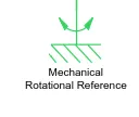
This block represents a mechanical rotational reference point, that is, a frame or a ground. Use it to connect mechanical rotational ports that are rigidly affixed to the frame (ground).
19] Simulink-PS Converter:- This block is used to Converts the Simulink input signal to a Physical Signal.

20] PS-Simulink Converter:- This block is used to Converts the input Physical Signal to a Simulink output signal.

21] Display:- This block is connected to a single our model and Show its value during simulation.
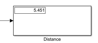
Above block measure the Distance 5.451 Kms in 2474 Second.
22] Scope:- This block is used to create plot and record the result.

Result Parameters Table:-
RESULT:-
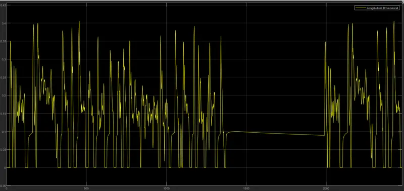
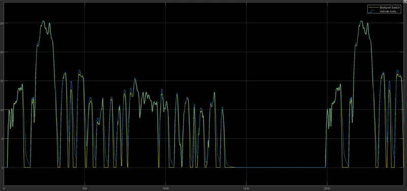
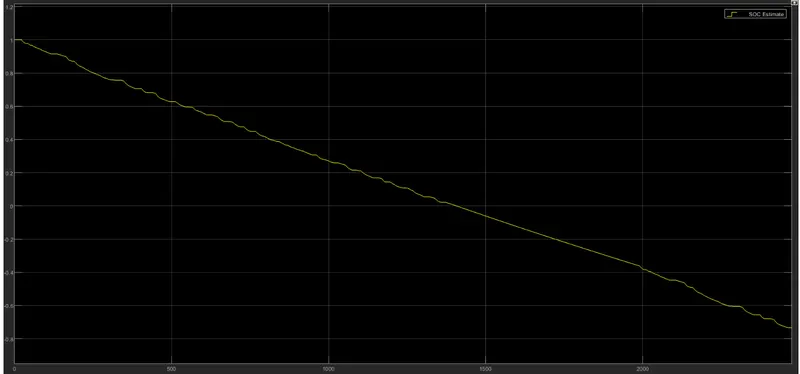
This plot shown as time vs State of Charge(SOC) in %.In this graph the battery was modelled to begin with an State of Charge(SOC) that is 100%. The model simulation start the SOC of the battery Decreses.When we have applied Vehicle braking mode.after brake mode we can see regenerating braking is working and to the maintain battery charge.after Simulation done the State of Charge(SOC) lies at 85% discharge in time 2474 Second.
CONCLUSION:-
- We have create a model of electric car which uses a battery and a Permanent Magnet DC motor using the Simulink Software is done.
- The distance travelled by my Electric vehicle(EV) model was 5.451 Kms in 2474 Second.
- The State of Charge (SOC) of the battery was Discharged efficiently upto 85 % from full charge.