Final Project: Design of an Electric Vehicle
MATLAB Model Of Electric Car With DC Motor And Battery:
- Block Diagram Of Electric Vehicle.
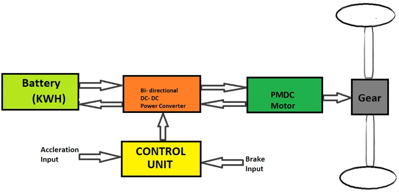
- Vehicle Body Consists of Wheels and Gears.
- DC Motor is used for vehicle Propulsion.
- Let us Consider a Simple Battery.
- Used 4 Quadrant switches as Power converter.
- Control unit consits of PWM modulation of DC voltage and Lonitudinal Driver
SIMULINK Model Of Electric Vehicle:
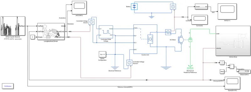
PowerTrain Blocks used in Simulink:
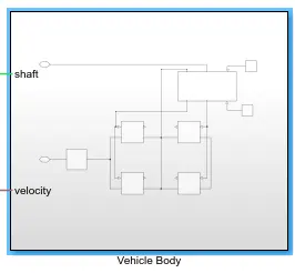
1.Vehicle Body: Complete vehicle body is considered as Subsystem as shown below.
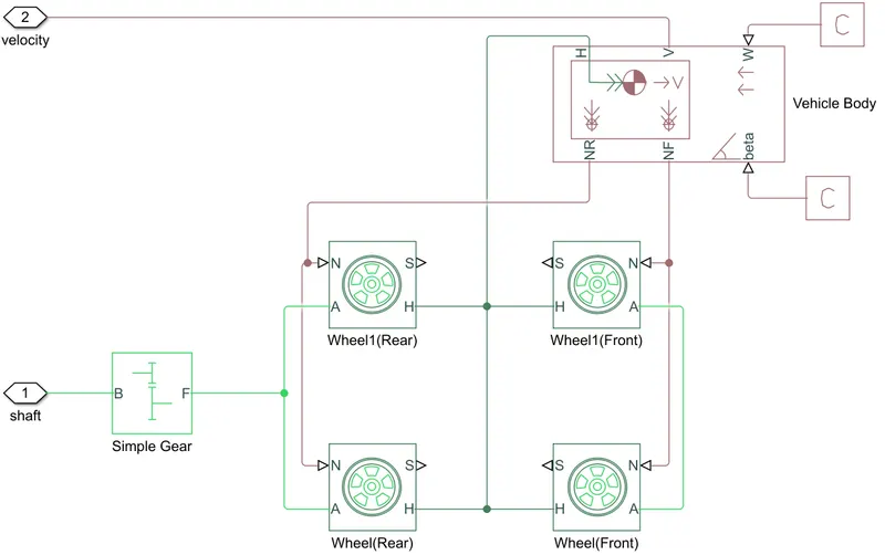
- Wheels: This Block represents the physical Wheel properites of a vehicle Specified by tire manufacturer.
- Four Wheel(2 for rear axle and 2 for front axle) Blocks are used and Each one has same specifications.
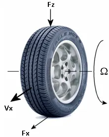
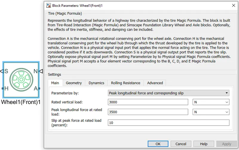
- Wheel Blocks are considered by default without any changes in all Parameters.
- If wheel parameters are specified then that will certainly effects the vehicle performance.
Ports:
N-Normal Force: This Input Port is used for Force to be applied on Wheel.
- Front Wheels N-Port is connected to NF port of vehicle Body.
- Rear Wheels N-Port is connected to NR port of vehicle Body.
S-Slip:Physical signal output port associated with the relative slip between the tire and road.
A-AXLE: This Mechanical Translational Port gives Mechanical link between two wheels.
- Both Rear and Front Wheels are connected through A-Port.
H-HUB: Mechanical translational port associated with the wheel hub that transmits the thrust generated by the tire to the vehicle body( maintain same speed in all wheels).
- All H-Hub ports of Wheels connected to H-port of Vehicle Body.
2.Vehicle Body: This Block gives the Vehicle Body Parameters to be set measured by Physical Vehicle.
In simulation all Parameters are considered as default to reduce simulation time.
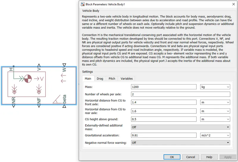
- H,NR and NF ports are connected to Wheels Ports of vehicle.
- beta port gives the vehicle body Inclination to the ground in Radians.
- W-Port Gives the wind velocity applied on front of the Vehicle body(Headwind Speed in m/s).
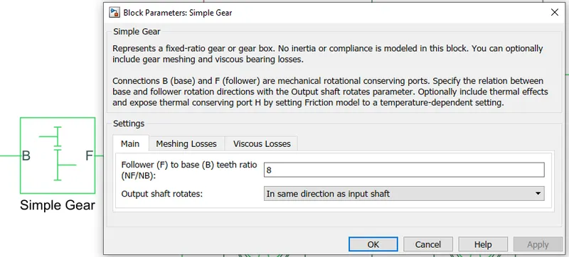
3.GEAR: Represents a fixed-ratio gear from Base(B) to Follower(F).
- Gear Ratio is specified by manufacturer as of now it is considered as 8.
4.DC Motor: This Block represents the electrical and torque characteristics of DC Motor.
Motor Parameters are set as:
No load speed of vehicle=8000 RPM
Rated Load Speed vehicle=5000 RPM
Rated Voltage =300 V
Rated Load of vehicle =60 KW
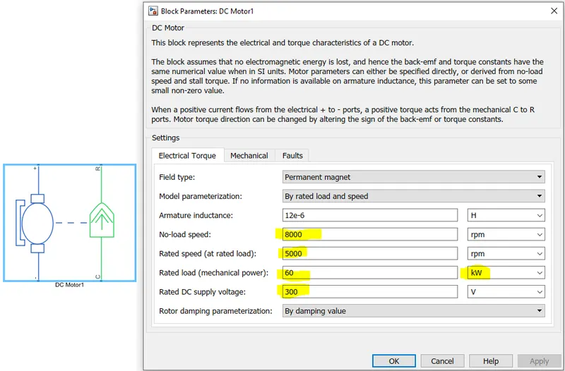
- Remaining all other Parameters( Resistance,Inductance,EMF....) are set as Default.
- Blue Part represents electrical Connection to Battery.
- Green part Represents Mechanical Part to be connected to shaft of Gear.
- R-Port is connected to B-Base port of Gear.
- C-Common port is connected to mechanical rotational reference frame.
5.References:
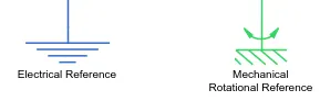
Electrical Reference : Gives the Nuetral Point to the electrical Circuit.
Mechanical Rotational Reference: This Block is considered as a rigid base (ground/frame) point of mechancial body.
Current Sensor: Sense the current taken by DC Motor and gives the feedback to Battery.

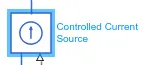
Controlled current Source : Maintain required amount of current to flow from the battery which is sensed from current sensor.
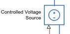
Controlled Voltage Source: Maintain Required amount of voltage to be maintain across DC motor which takes voltage level signal from driver.
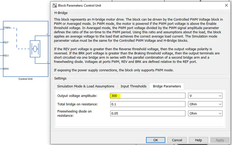
6.H-Bridge: The H-Bridge block output is a controlled voltage that depends on the input signal at the PWM port.
PWM: If the input signal has a value greater than the Enable threshold voltage parameter value, the H-Bridge block output is on and has a value equal to the value of the Output voltage amplitude parameter.
If it has a value less than the Enable threshold voltage parameter value, the block maintains the load circuit using Freewheeling diode.
- REV and BRK mode are grounded in simulation.
-
Output voltage: set to 300v (consider as Motor rated voltage)
-
Simulation mode is averaged to reduce the simulation time.
REV: voltage that controls when to reverse the polarity of the H-Bridge block output.
BRK: voltage that controls when to short circuit the H-Bridge block output.
Power supply : Power supply can run in two model Internal and External Mode.
External Mode:
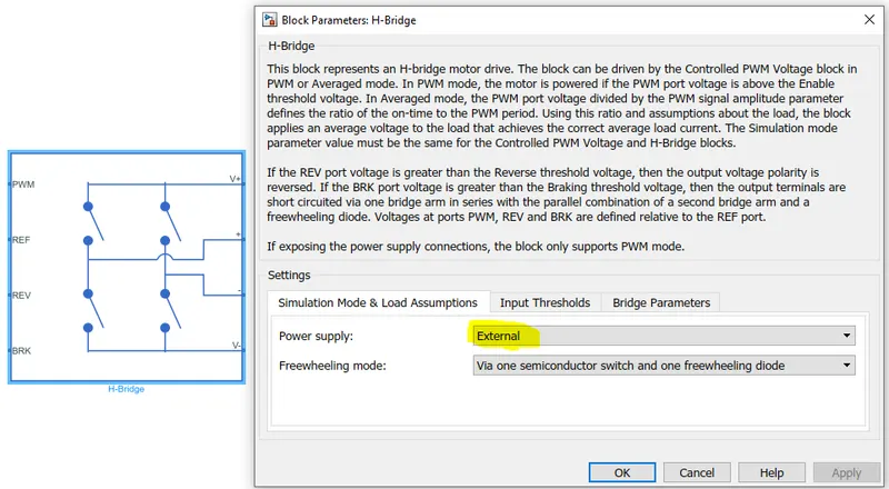
- Gate Pulse is given by external DC source to Semi conductor switches.
- If power supply is internal then Gate pulse is obtain internally(Based on Inductance value of motor) such a way that motor runs continously.
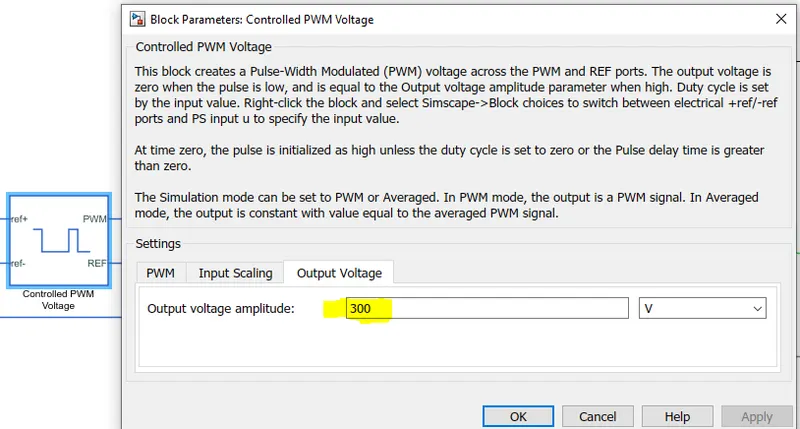
7.Controlled PWM voltage: The Controlled PWM Voltage block represents a pulse-width modulated (PWM) voltage source.
Simulation Mode is AVERAGED to reduce simulation time.
Output voltage: set to 300v (consider as Motor rated voltage)
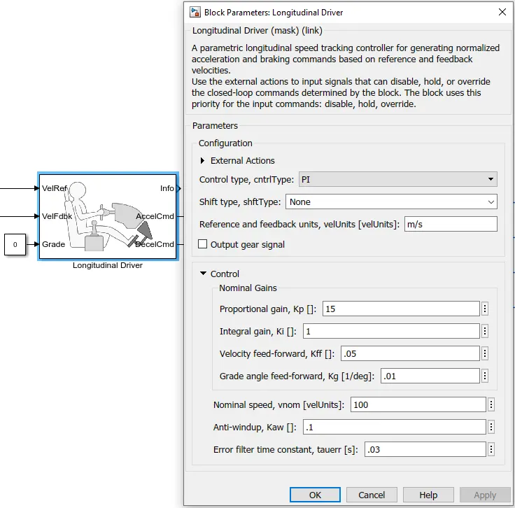
8. Lonitudinal Driver:(Acts as Driver of vehicle)The block generates normalized acceleration and braking commands that can vary from 0 through 1.
It is Speed Tracking Block which uses a PI controller to reduce the error between Reference velocity and output velocity and gives Accleration and brake commands to Motor through H-bridge.
All Parameters are set as default.
Grade is set as zero so, there is no gradeability in Vehicle.
9.Drive Cycle:The Drive Cycle Source block generates a standard or user-specified longitudinal drive cycle. The block output is the specified vehicle longitudinal speed
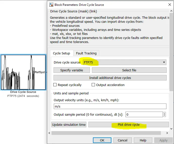
FTP75: used to generate velocity across vehicle and evaluate the vehicle performance.
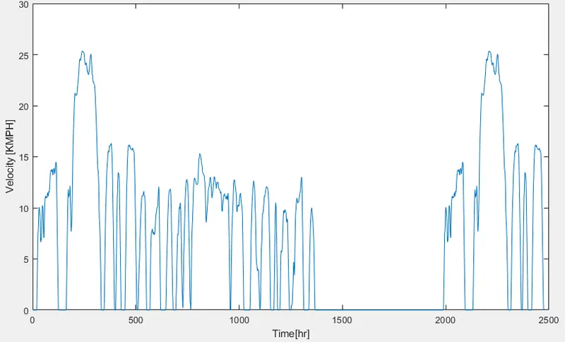
Run Time: 2474sec
10.Battery: This block represents the Physical model of battery.
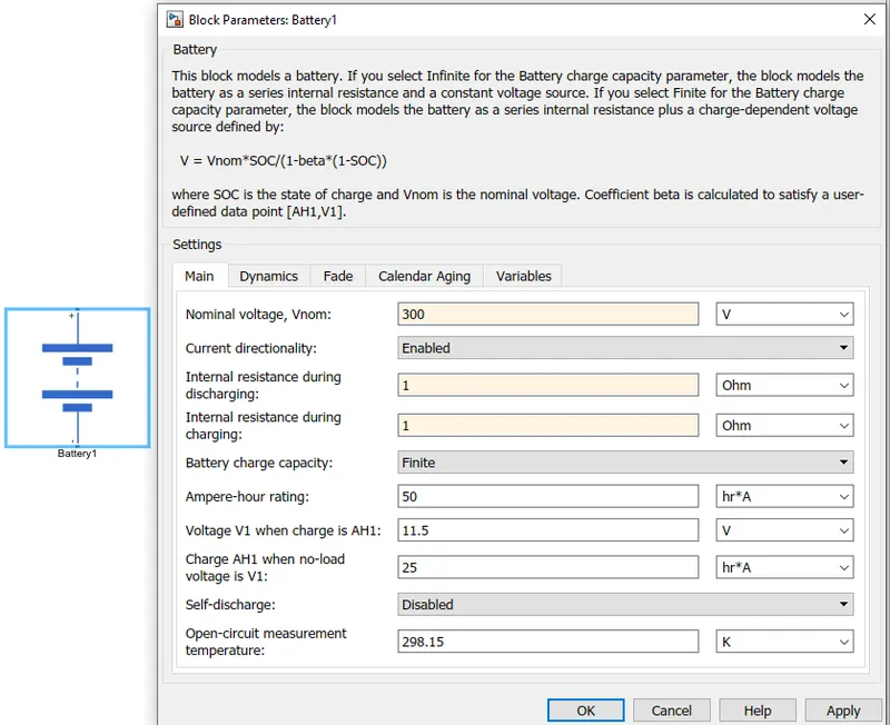
- Battery voltage=Motor rated voltage =300v
- Amphere-Hr rating =50AH
Calculation Of State of charge (SOC):
- To calculate the SOC from current (I) utlisied by motor is defined as
`SOC(t)=(1/C)int_0^tI(t)dt`
where C= Battery capacitance(AH)
I= current
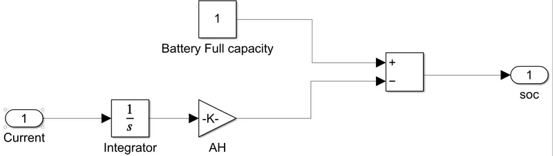
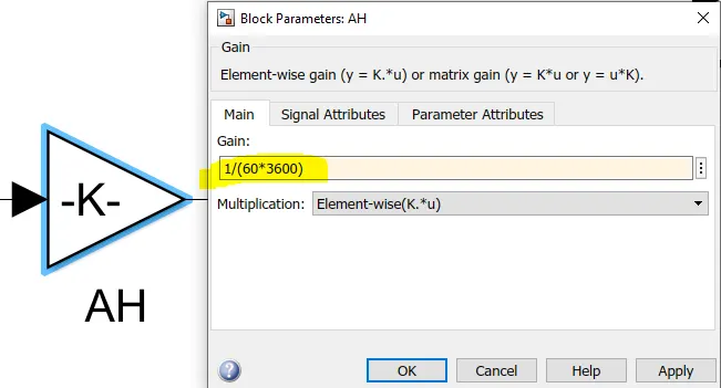
Simulink model of SOC: Current is Integrated and Divide with battery Ampere hour rating (Gain Block)in seconds then subtracted the obtain result from battery full capacity.
Simulation Results:
1.Ref Velocity Vs Output velocity:
Red : Output Velocity
Blue : Reference Velocity
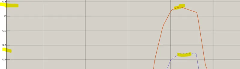
- Output velocity is almost follows to reference veocity with minor distructions.
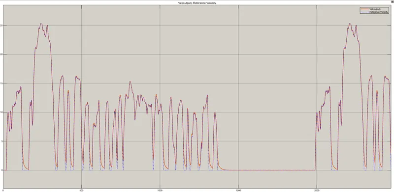
- Though Brake is fully applied ,output velocity not becomes zero due to Inertia of motor and vehicle.
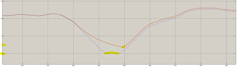
- Peak output velocity is greater than reference output veocity due to motor inductance voltage.
SOC:
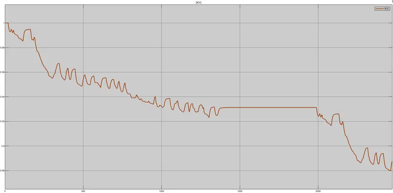
- Battery is Discharged from 100% (1) to 88% (0.88) throughout drive cycle.
- Battery is also charged during simulation due to Regenerative braking is applied.
- Discharge of Battery Follows the drive cycle pattern.
Accleration and Brake Commands:
Red : Accleration command
Blue : Brake Command
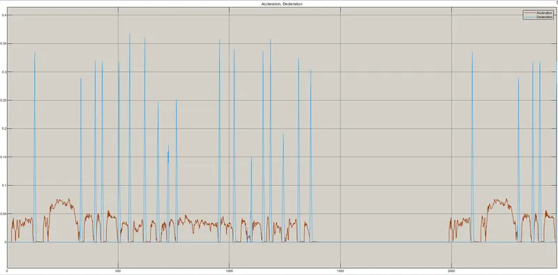
- We can observe whenever brake command is given Battery tries to charge.
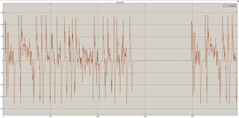
Current Flows in DC Motor:
- Peak current is 180A in both Accleration and braking modes.