Project
AIM: Simulation of CVT in system level for All-Terrain vehicle.
All-Terrain vehicle:
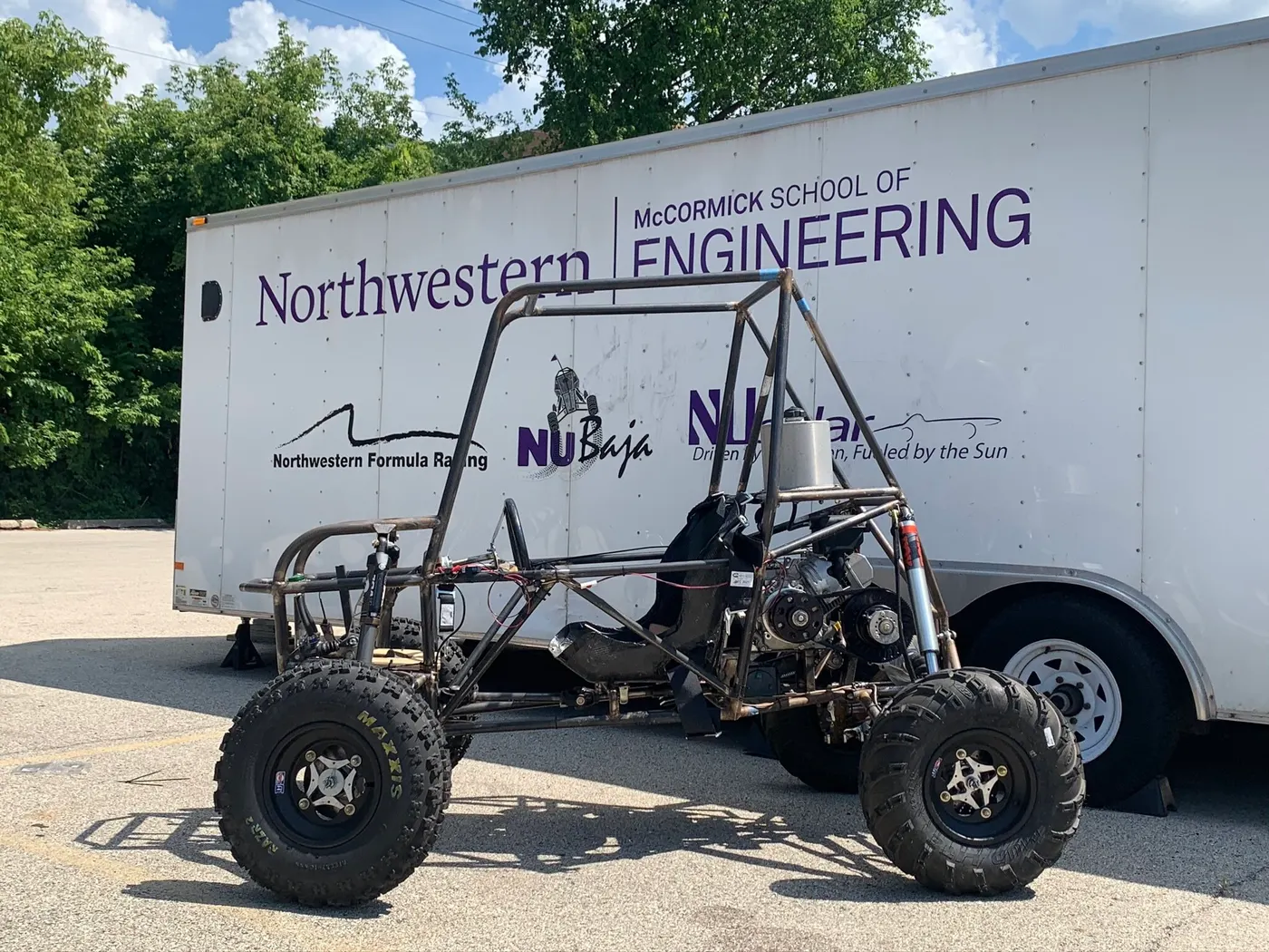
An all-terrain vehicle (ATV) is defined as a motorized off-highway vehicle.which is specially designed for a off roads driving. ATV is designed to
travel on four low-pressure or non-pneumatic tires, having a seat designed to be straddled by the operator and handlebars for steering
control. rider sits on and operates these vehicles like a motorcycle. Used for very rough terrain, jumps, maneuverability and endurance.
The design process of this single-person vehicle is iterative and based on several engineering and reverse engineering processes.
Creo Parametric 1.0 (Pro Engineer) was the CAD software used for designing and ANSYS 13.0 was used to analyze the Impact test and all.
Continuously Variable Transmission(CVT):
A CVT or Continuously Variable Transmission is an automatic, single speed, and gearless transmission that can shift through an infinite number of
gear ratios. This ability to seamlessly shift through these different gears provides a number of benefits including extremely smooth shifts and
exceptional fuel economy.
Working:
There is a pulley system with cones at each pulley, all connected by a chain belt. The cone moves closer together or further apart to increase or
decrease the diameter at which the belt operates. This is how the unit changes gear ratios and allows the unit to quickly “shift” into the necessary
gear ratio to allow for either increased power and/or increased fuel economy when needed.It is considered an automatic transmission it does not
shift at all like a traditional gearbox.
Simulink CVT:
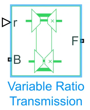
Represents a variable ratio gearbox such as implemented by mechanical belt CVT, electric, or hydraulic transmissions. The physical signal input
r defines the ratio of input to output angular shaft velocities.Connections B (base) and F (follower) are mechanical rotational conserving ports.
Specify the relation between base and follower rotation directions with the Output shaft rotates parameter.
1.BAJA ATV Simulink Model:
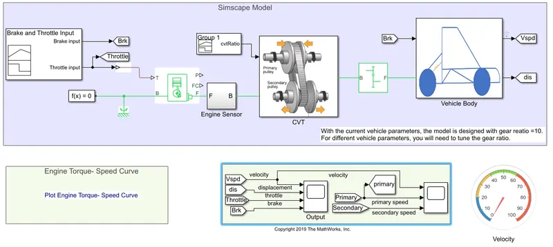
- system designed by combination of both simulink and simscape blocks.
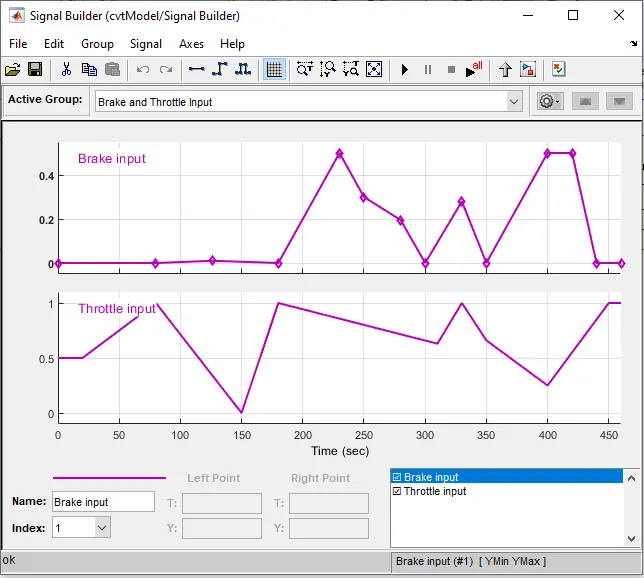
- Signal builder block is used as input for Throttle input, Brake input and CVT gear ratio.
- Guage Dashboard named as velocity is connected to observe the simulation results for the given input in model itself.
- Additional ports added to scope and signal naming is given to compare the simulations output.
Generic Engine: The Generic Engine block represents a general internal combustion engine. Engine types include spark-ignition and diesel. A throttle physical signal input specifies the normalized engine torque.
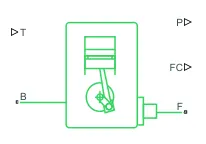
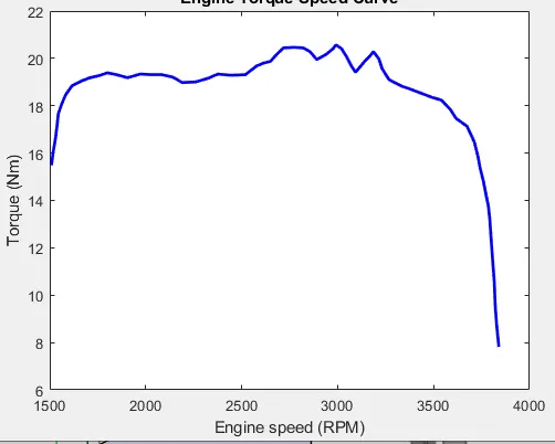
By default, the Generic Engine model uses a programmed relationship between torque and speed, modulated by the throttle signal but Speed-power and speed-torque parameters are to be provided from the characteristics of engine model.
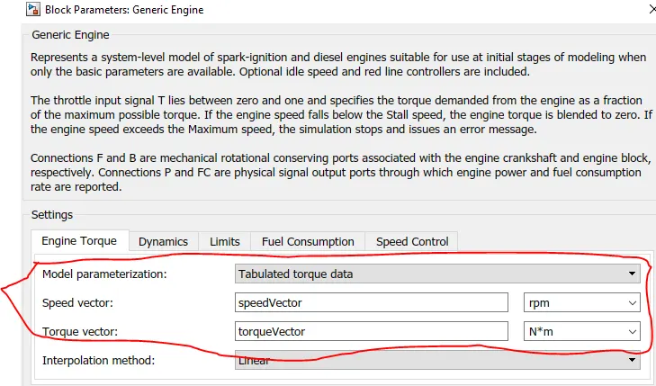
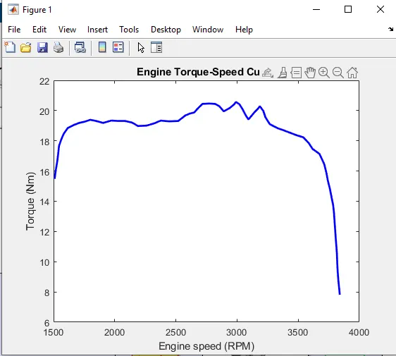
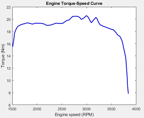
Engine Speed-torque characteristics curve taken from the Baja model and defined to engine.
SubSystems:
CVT gear ratio:
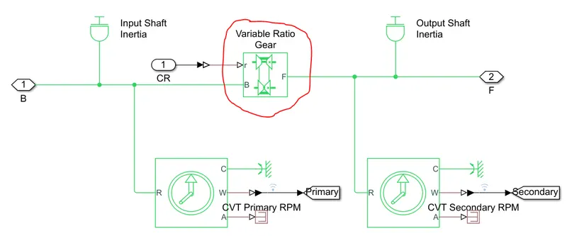
- Both Primary and secondary shafts Inertia are given to get results accurately.
- Primary and Secondary RPM are sensed by Rotational motion sensor blocks, As shown above.
Engine sensor:
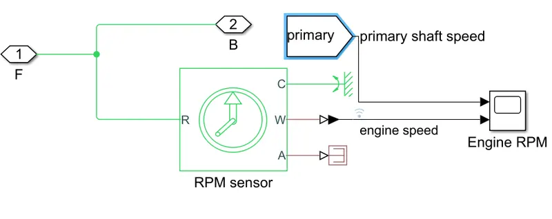
- This sensor sense the RPM of Engine with respect to the throttle input.
- primary shaft speed signal is added to scope to compare result for given input.
Vehicle Body:
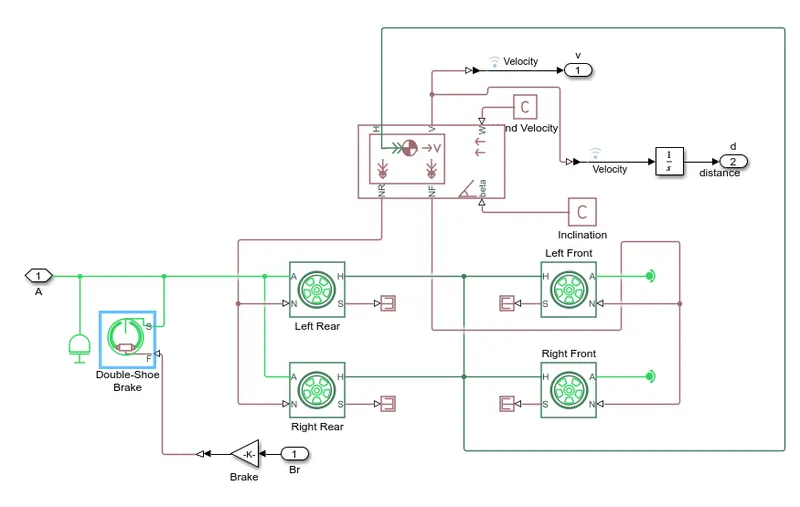
- this System contains three main blocks
- Double Shoe brake block which acts as brake to the vehicle body and its parameters are default set.
- Tire Block named as Left and Right Rear/Tear which acts tires to the vehicle and these parametes are default set.
- Vehicle Body Block is used to determine the values of like body mass and its friction. these values are to be provide from actual system.
- Distance travelled by vehicle is taken as output get by integrating the velocity with time.
Inputs:
Initial Condition: To RUN the Simulation Minimum value to be: Brake Input=0,Throttle Input=0.5 at time t=0sec
- Throttle input is to Acclerate the vehicle is given from Minimum 0 to maximum 1.
- Brake Input is to Decelarate the vehicle is given from Minimum 0 to maximum 1.
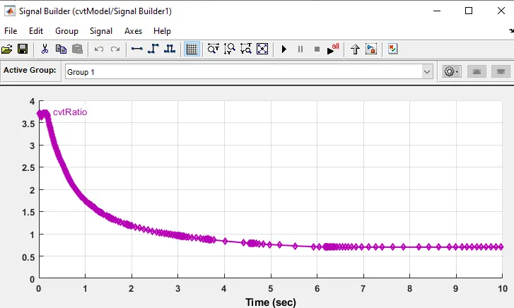
- CVT Gear Ratio input is to define the Gear ratio to be maintain for given speed input.
Simulation Results:
Velocity and Distance:
- Velocity and distance are taken as output for evaluating simulation.
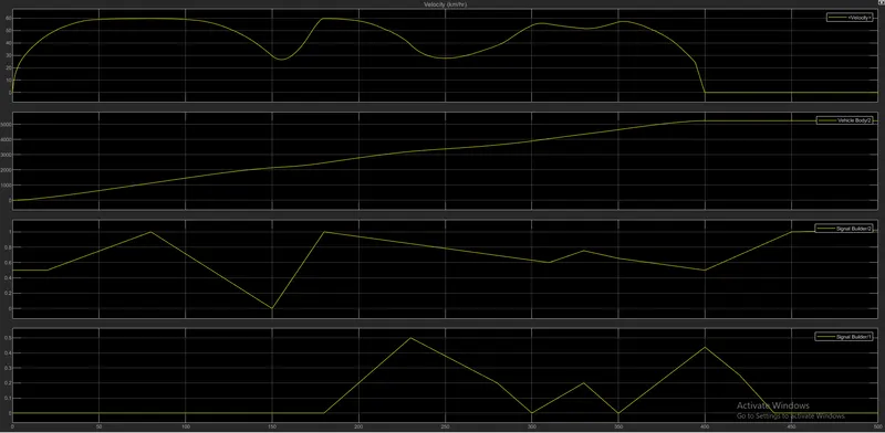
- Results and Observations are Tabulated Below.
|
Time (Sec) |
Throttle | Brake | Observation |
| 0 to 20 sec |
Constant at 0.5 |
Constant at 0 |
velocity Increases from 0km/hr to 50km/hr exponentially. |
| 20 to 80 sec | Increased from 0 to 1 | Constant at 0 | Velocity Increases From 50km/hr to 60km/hr and maintain constant at 60Km/Hr. |
| 80 to 150 sec | Decrease from 1 to 0 | Constant at 0 | Velocity Decreases from 60km/hr to 25km/hr exponentially. |
| 150 to 180sec | Increased from 0 to 1 | constant at 0 |
velocity Increases from 25km/hr to 60km/hr exponentially.Though Throttle input<0.5, velocity increased as velocity not equal to zero at 150 sec. |
| 180 to 230sec | Decreased from 1 to 0.85 | Increased From 0 to 0.5 | Velocity Decreases from 60km/hr to 40km/hr in 20secs. Though Full brake applied vehicle is not halt as thottle input force is grater than brake applied force. |
| 230 to 280sec | Decreased From 0.85 to 0.80 | Decreased from 0.5 to 0.2 | Velocity decreases from 40km/hr to 30km/hr and again increased 30 to 40km/hr Due to throttle input force is greater than Brake applied force. |
| 280 to 300sec | Decreased from 0.80 to 0.65 | Decreased from 0.2 to 0 | Velocity Increased from 40km/hr to 55km/hr as Brake Input completely decreased and throttle input slightly decreased. |
| 350 to 400sec | Decreased From 0.65 to 0.3 | Increased from 0 to 0.438 | Velocity Decreased from 58km/hr to 0km/hr as complete Brake is applied and Throttle input<0.5. At 400 sec Vehicle Halted and distance travelled by vehicle is 5233.5meters |
| At 400sec |
completely increased from 0.3 to 1 |
Completely Decreased from 1 to 0 | Velocity Doesn't increase again as vehicle velocity=0 and throttle input<0.5 at t=400sec, |
- Distance increases acoording to speed/velocity of vehicle and stop only if vehicle halts.
CVT Shaft Speed: Primary and secondary shafts speed are shown below
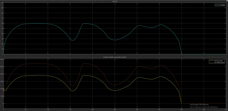
Observation: Output velocity is varying same as primary and secondary shaft speed.
|
|
|
|
|
Engine Speed:
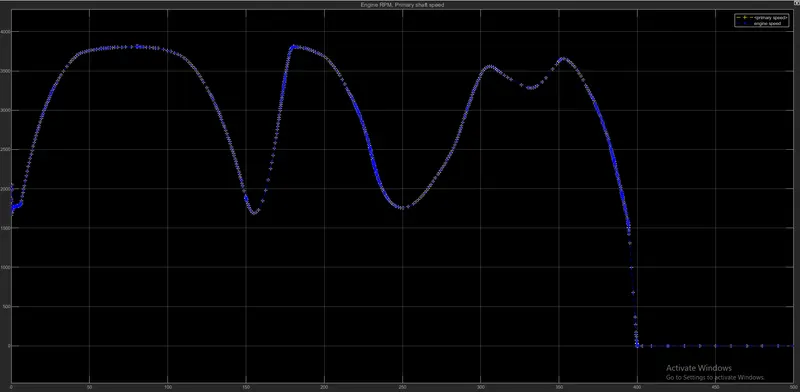
- Both primary Shaft speed and Engine Speed are varying equally according to throttle input and brake input.\
Overall observations:
|
|
2.BAJA ATA Simulink Model using Dashboard blocks:
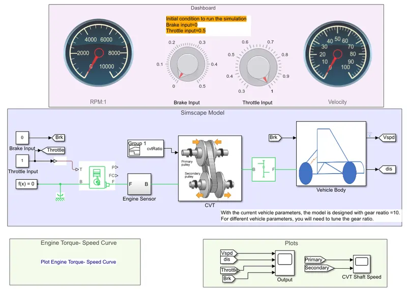
- Here Knob Dashboard block is used to give Throttle and Brake input.
- Engine RPM and Vehicle veliocity are checked by guage block named as RPM and velocity.
Defined Values:
1.Speed-Torque Characteristics for Generic Engine;
2.CVT Gear Ratio:
Simulation Results:
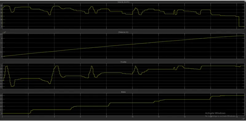
By varying knob Results are simulated as follows.
|
|
|
|
Conclusion:
- As Brake Input Varies initial throtle Input condition also varies to run the simulation.
- Maximum Velocity=60km/hr for maximum throttle input=1 and No brake applied (brake=0).
Limitations:
|
3.BAJA ATV Simulink Data MODEL:
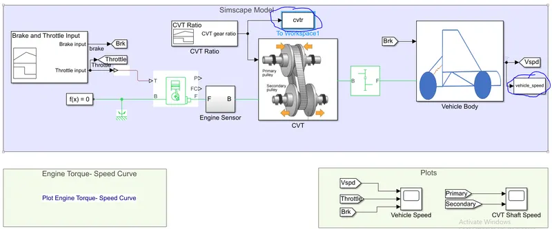
To workSpace Block: To Workspace block writes input signal/output signal data to a workspace. During simulation, the block writes data to an internal buffer. When you pause the simulation or the simulation completes, that data is written to the workspace. Data is not available until the simulation pauses or stops.

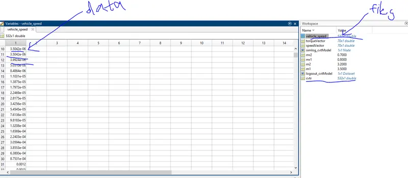
- Here in this model two to workspace block files are used for saving CVT gear Ratio Data and output Vehicle speed Data to workspace.
- After running the simulation data file and values are visible in workspace in excelsheet form.
Parameters Changed:
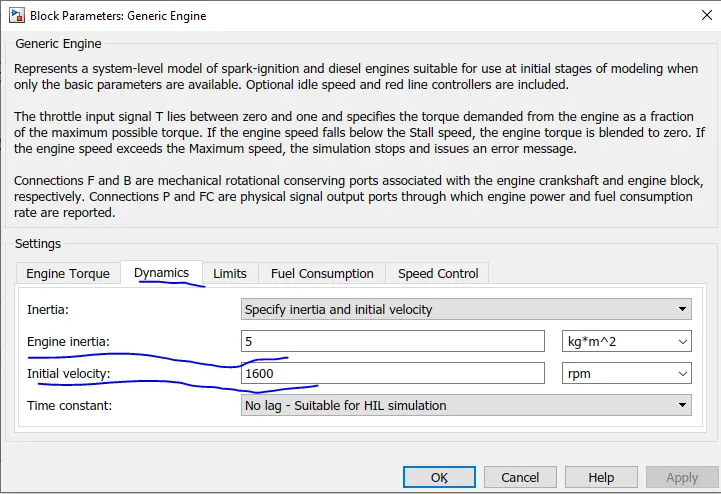
- Generic engine block parameters are changed.
- Simple Gear block given to vehicle body Ratio also changed.
Gear Ratio=12
Defined Values Data:
- CVT gear Ratio is defined from Signal builder block.
- Torque-speed curve characteristics are same as previous model.
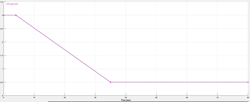
Input:
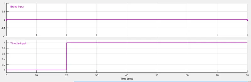
- Brake and Throttle Input are given as follows by using signal builder.
Simulation Results:
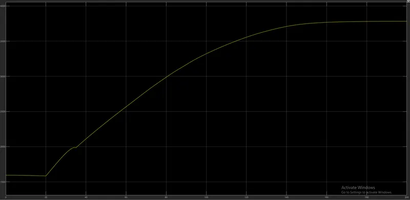
Engine RPM:
- Initial engine speed=1750rpm upto 20sec due to throttle input=0.
- At t=20sec,velocity increases linearly and saturated at 3800 RPM at 160sec.
Vehicle speed and Distance
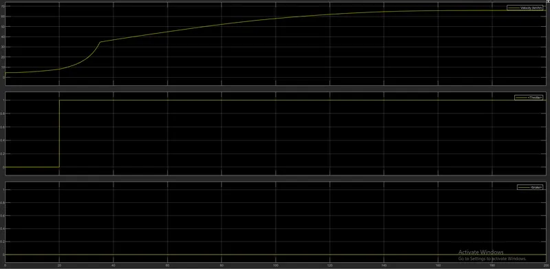
- Though Intial Throttle Input=0 upto 20sec, Vehicle velocity Increases and reached to 65km/hr at 140sec Due to changes in Engine parameters and CVT Ratio Defined values.
- Distance is not taken in systam as it changes linearly same as previous model.
Shaft Speed:
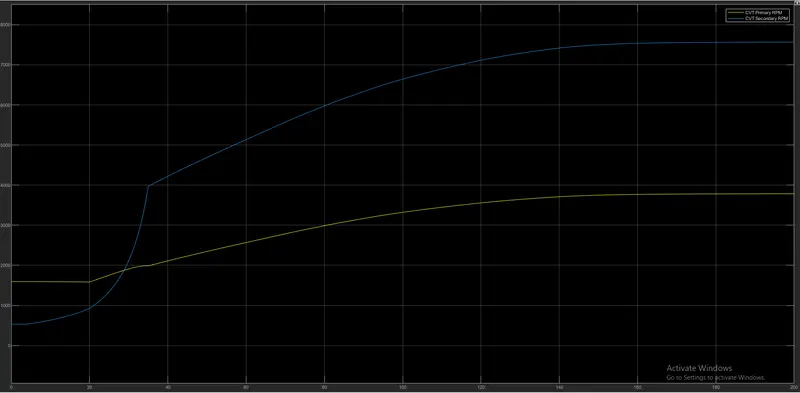
- At starting of system Secondary shaft speed is less than primary shaft speed as vehicle is at stand still and ready to start.so, torque of vehicle is more at this instant than compare to speed of vehicle to move the vehicle.
- As initial throttle input=0, rise in secondary shaft speed but primary shaft speed increase less than speed of secondary shaft speed. With constant throttle input =1 after 20sec, both shaft speed increases gradually and saturated at maximum point of RPM and torque of will be less.
- Max Secondary shaft speed=7500RPM.
Max Primary Shaft Speed=3800RPM.
4.BAJA ATV simscape Model using (n-D) lookup Table:
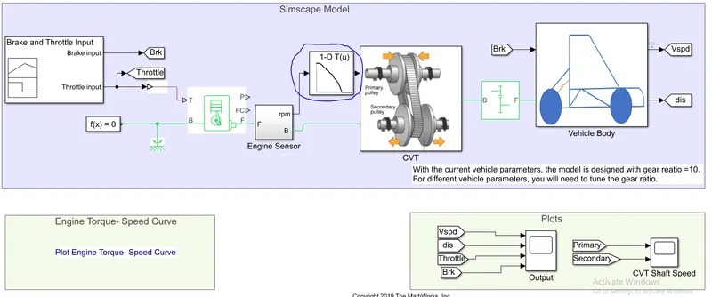
(n-D lookup Table):
The block maps inputs to an output value by looking up or interpolating a table of values you define with block parameters. The block supports flat (constant), linear (linear point-slope), Lagrange (linear Lagrange), nearest, cubic-spline, and Akima spline interpolation methods. You can apply these methods to a table of any dimension from 1 through 30.
In the following block, the first input identifies the first dimension (row) breakpoints, the second input identifies the second dimension (column) breakpoints, and so on.
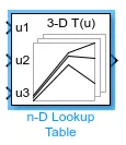
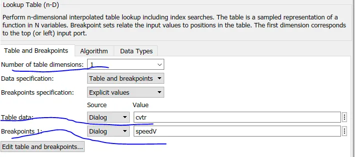
- Here in this model, 1-D Dimension is used.
- Data values to interpolate the graph are taken from cvtr(CVT gear ratio) file from workspace.
- Break points are given from engine speed.
After interpolation graph will be:
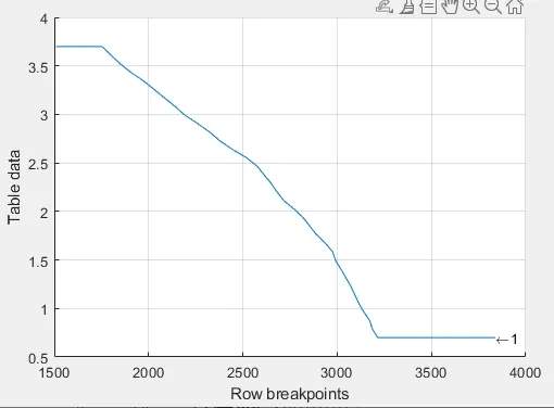
- This Graph shows that at what gear ratio speed to be maintain i.e.,At 3000 RPM Gear Ratio=1.5 from graph.
This plot graph data values given to CVT gear ratio block. to obtain different velocities for given throttle and brake input.
- Torque speed characteristics are same as previous model.
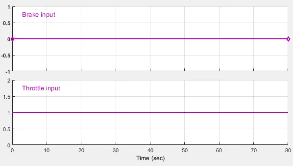
Inputs: Brake Input=0,Throttle Input=1.
Simulation Results:
Velocity and Distance:
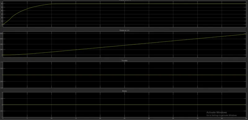
- Velocity Increases nearly linearly and reached to Max. Velocity=60km/hr at t=10sec due to constant and max throttle input=1.
- Distance also increases linearly and reached to 600meters in 40sec.
CVT Shaft Speed:
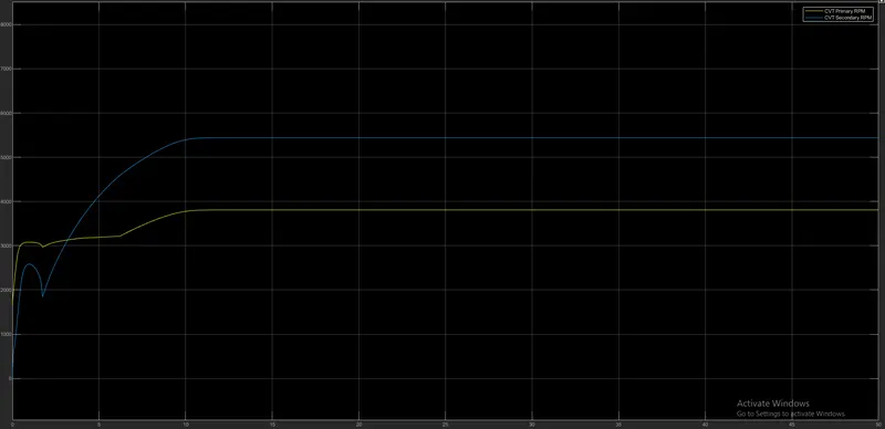
- Both Primary and secondary shafts are constant at t=10sec.
- Secondary shaft speed> primary shaft speed.
- Max Primary Shaft speed=3800RPM
- Max secondary shaft speed=5500RPM.
- Engine RPM is same as Primary shaft speed RPM.
5.BAJA ATV Simscape Model using output velocity for CVT ratio:
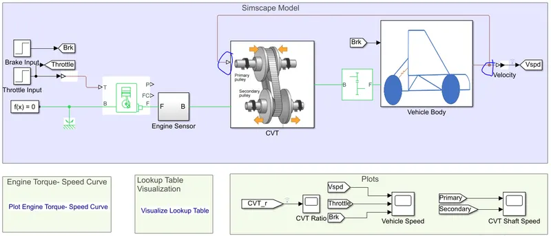
- In previous Model, Breakpoints for lookup table are given from engine speed.
- In this model, Breakpoints for lookup table are given from output velocity.
CVT Subsystem:

PS (1D)lookup Table:
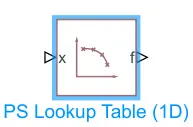
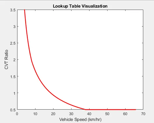
The PS Lookup Table (1D) block computes an approximation to some function f=f(x) given data vectors x and f. Both the input and the output are physical signals.
The length of the x and f data vectors provided to this block must match. Also, the x data vector must be strictly monotonic, either increasing or decreasing.
thus CVT gear ratio values are defined.
Torque-speed characteristics are same as previous model.
Parameters Changed:
Engine parameters are changed from previous model.
- Engine Inertia=5
- Intial Velocity=1600
Gear Ratio=12
Simulation Results:
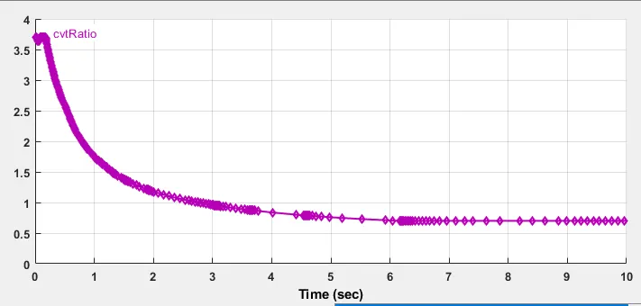
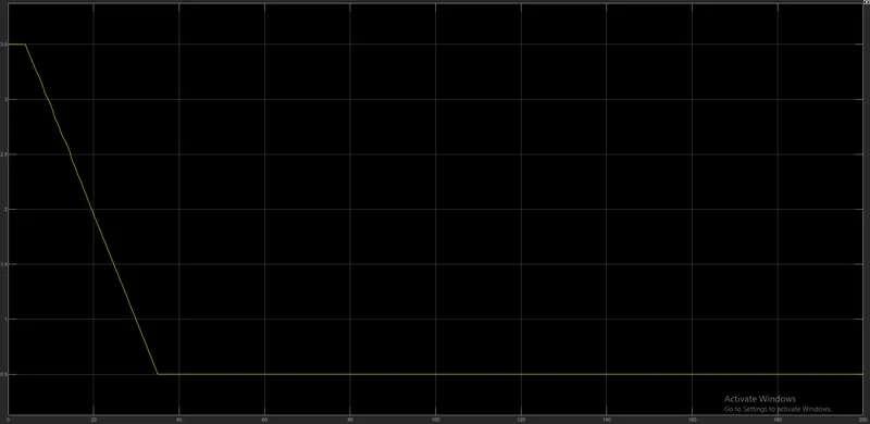
CVT Ratio:
- CVT ratio graph obtained from output velocity is same as previous model n0.3 BAJA ATV simscape Model using Data:
- Output Velocity for given Throttle and Brake Input:
Brake and throttle input are given from step block
Brake input=0; Throughout simulation.
Throttle input=0.3, at t=0 to t=20sec
Throttle Input=1, at t=20 to t=200sec
- Velocity Increased from 5km/hr at t=0 to saturated at 65km/hr at t=140sec.
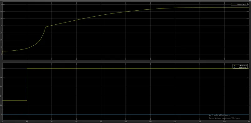
- Results are same as previous model no.3
CVT Shaft Speed:
- Engine RPM speed graph is same primary shaft speed.
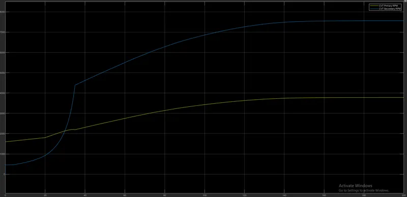
6..BAJA ATV Simscape Model using output velocity for CVT ratio(Dashboard):
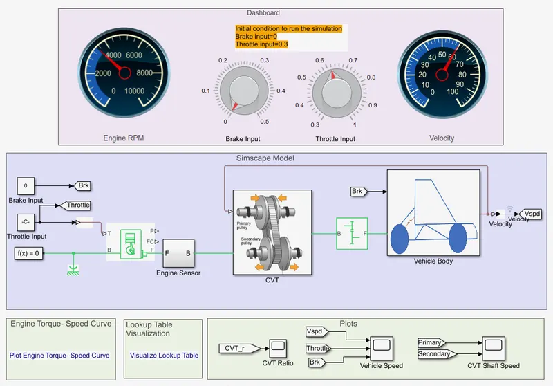
- Using Dashboard blocks Knobs for throttle input and brake input, Observing the output velocity of vehicle and engine RPM in model itself by Guage Blocks.
Inputs: Inputs are given from Dashboard block Guage.
Simulation Results:
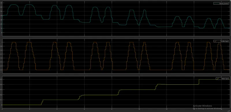
Velocity:
- By varying throttle guage and Brake guage simulation results are as follows.
- At Brake=0;throttle=1, Max velocity=65km/hr. i.e., max velocity vehicle can obtain is 65km/hr.
- At Brake=1;Throttle=0.3, Min velocity=10km/hr. i.e., vehicle can obtain 10km/hr velocity even after full brake applied and throttle input=0.3.
- Likewise for different inputs simulation result can be observe in less time by using dashboard blocks.
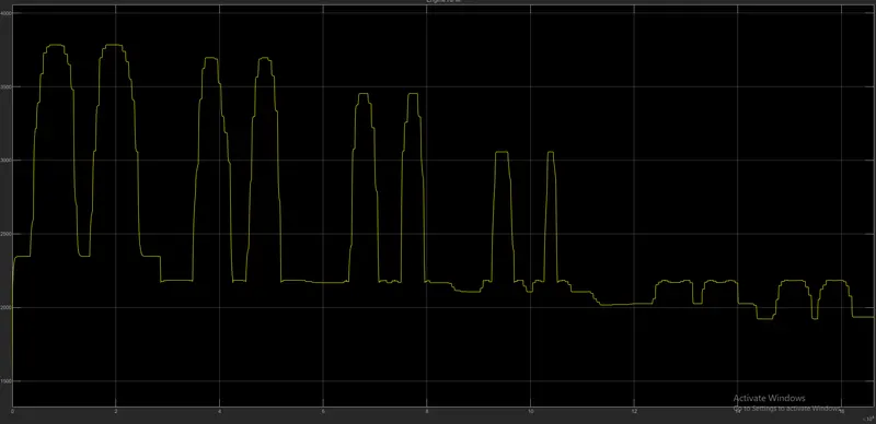
Engine RPM:
- Max speed=3800RPM for brake=0; throttle=1
- Initial speed=2300RPM for brake=0;throttle=0.3.
- Minimum speed=1850RPM for brake=1;throttle=0.3
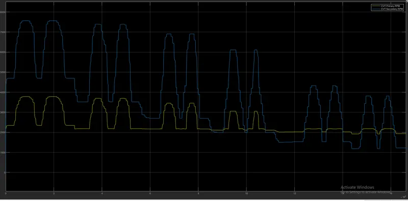
CVT Shaft speed:
- At t=0sec, secondary shaft speed> primary shaft speed.
- Though secondary speed< primary speed, velocity`!=`0 due to throttle input=0.3.
- Primary shaft spped=engine speed.
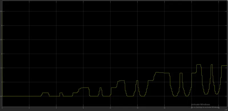
CVT Ratio:
- Max velocity 65km/hr obtain at minimum gear ratio=0.5
- Min Velocity 10km/hr obtain at Gear ratio=1.6
Limitations:
- Initial condition not required
Though initial throttle input=0 and brake input=1 simulation can be run and results are same.