Week -2
Aim: To Operate Door bell using Solenoid in Simulink
Working: It works under the principle of Electro Magnetic produced in solenoid by giving DC supply in Pulse waveform.
Simulink Model:
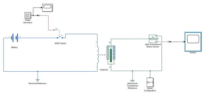
Procedure: Blocks used
Pulse generator: to generate time signals to control switch operation.
Source Link:Simulink / Sources
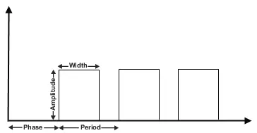
In this pulse generater Block parameters can be changed such as Phase,Period,Amplitude and Width.
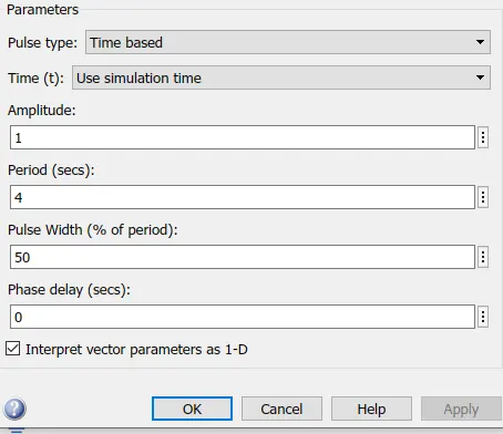
To get Pulse of amplitude=1, for 2sec in period=4sec without phase delay the parameter settings to be as follows:
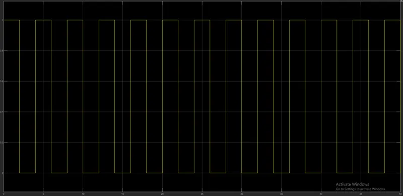
Output:
Voltage Source; Battery/controlled voltage source
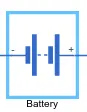
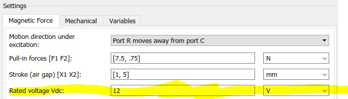
Battery: parameters to be set for matching battery voltage to solenoid voltage.
Parameters:
Battery:

Solenoid:
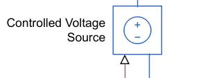
Controlled Voltage source: no need to set parameter as automatically generate require amount of voltage to solenoid.
Solenoid : To generate magnetic field by that Soft iron armature gets attracted to ring the bell.
Source Link:Simscape / Electrical / Electromechanical / Mechatronic Actuators
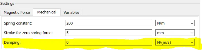
in solenoid Damping Parameter is changed to get desired output.
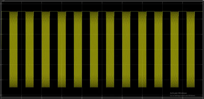
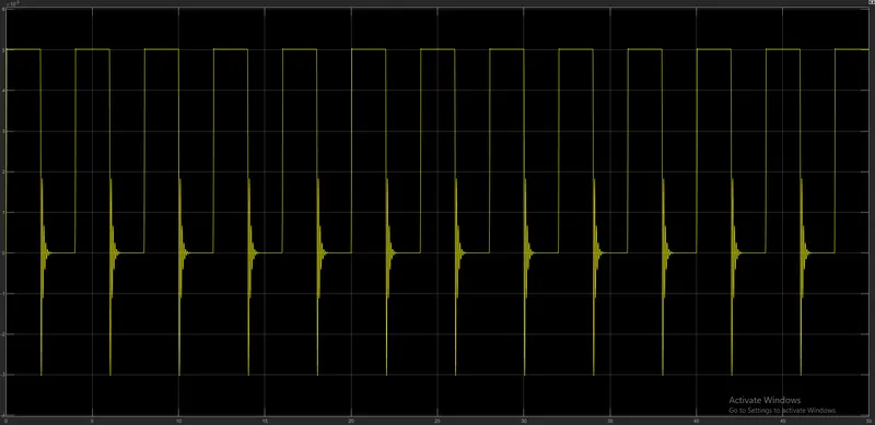
Damping: As damping factor increases oscillations will be decrease.
output:
Case-1: Damping=0
Case-2: for Damping=1
For Damping =10
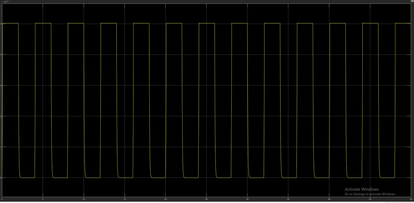
Hence We can prove that as Damping factor increase oscillations in armature decreases.
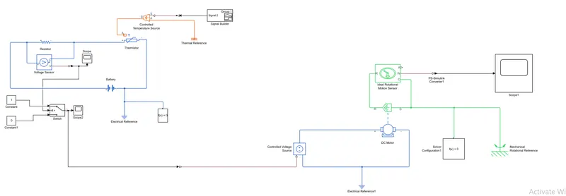
2.Aim: Using a thermistor to sense the temperature of a heater & turn on or turn off the fan using Simulink.
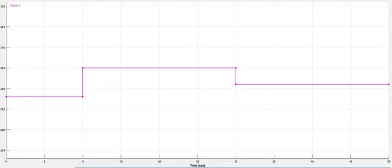
Condition: Temperature source: 20 °C from 0 to 10 seconds, 27 °C from 10 to 30 seconds, 23 °C from 30 to 50 seconds
Fan conditions: ON if the temperature above 25 °C, OFF otherwise
Simulink Model:
Blocks Used:
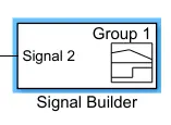
Signal Builder: link-Simulink / Sources
We can generate Require form of input signal with respect to time.
Output;
Note: for This system temperature condition given in Degrees But we have to directly provide temperature in Kelvin. For that
1 degree= 274Kelvins.
controlled temperature source: link-Simscape / Foundation Library / Thermal / Thermal Sources.
The Controlled Temperature Source block represents an ideal source of thermal energy that is powerful enough to maintain specified temperature difference across the source regardless of the heat flow consumed by the system.
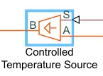
- A & B are Inlet and Outlet of source.
From A to B is positive i.e., Ta-Tb=positive and vice versa.
- S- control signal given to source.
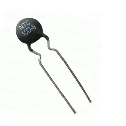
Thermistor: it is a Device which its Resistance varies with Temperature.
- link-Simscape / Electrical / Sensors & Transducers
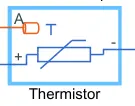
- there are two types: 1. NTC thermistor : Resistance decrease with increase in temperature and vice versa.
2. PTC Thermistor : Resistance increase with increase in temperature and vice versa.
Voltage sensor: Link- Electrical systems.
Which converts voltage measured in electrical circuit or across any passive element to Physical signal proportional to it.

NOTE: At SCOPE we can get an error as follows due to insufficient derivatives at PS-simulink converter.

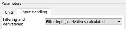
To Debug this error we have to change parameter at ps-simulink converter across signal builder as
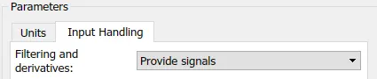
from provide signals to Filter input,Derivatives calculated to change signal builder simulink value to physical value of thermal
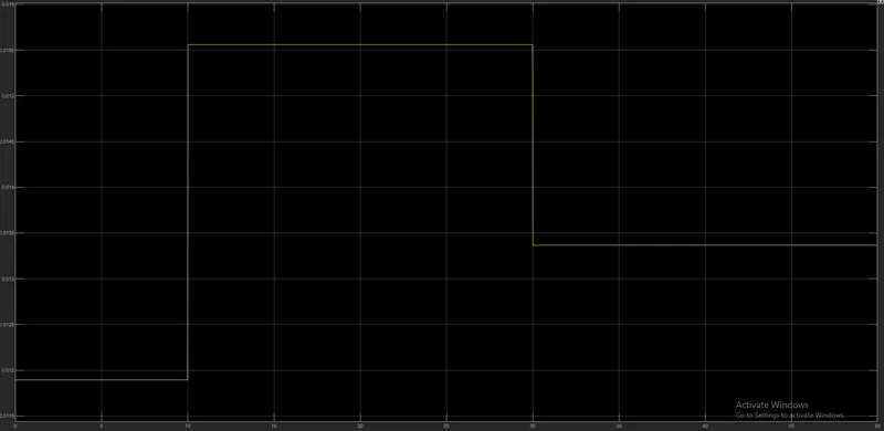
Output;For given input signal at signal builder block output will be at voltage sensor (Scope) as follows.
Switch: Link-
-
Simulink / Commonly Used Blocks
Simulink / Signal Routing
HDL Coder / Commonly Used Blocks
HDL Coder / Signal Routing

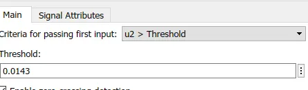
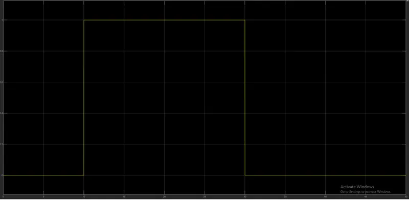
- From 0 to 10sec: Temp=20deg, hence switch=off.
- From 10 to 30sec: Temp=27deg, hence switch=on.
- From 30 to 50sec: Temp=23deg, hence switch=off.
Hence we obtain working of fan only when temp=25deg.
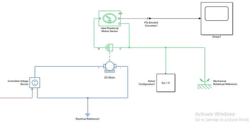
BY connecting DC motor along with Required Mechanical block as shown below model can be run
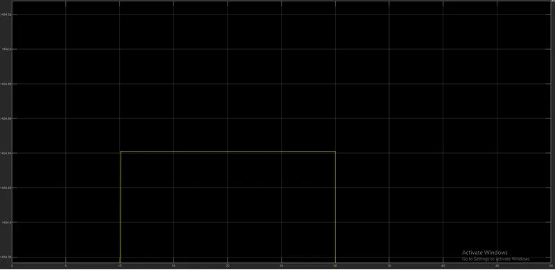
Output at Scope1: Fan is on from 10 to 30sec at 27Deg
Completed.