Week-7 Challenge: DC Motor Control
1. A. Explain a MATLAB demo model named ‘Speed control of a DC motor using BJT H-bridge’.
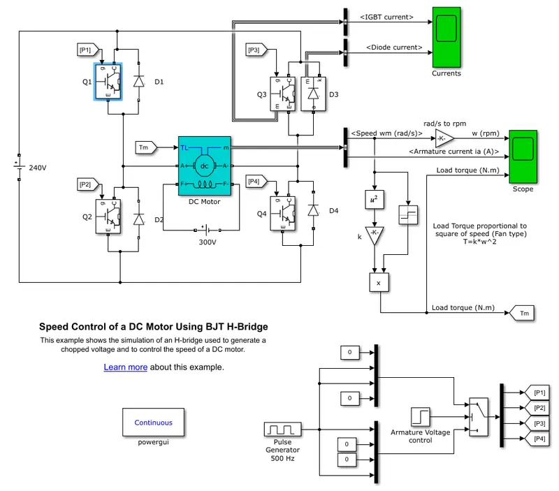
- In the above example uses four IGBT along with Anti Parallel diode to change the direction of current flow in motor.
- Load applied on motor is Fan Type load of Torque(`tau`) speed(`omega`) equation is
`tau=k*omega^2`
- Motor can Operate in two modes: 1)Foward direction : Q1 & Q4
2)Reverse Direction : Q2 & Q3
- DC Motor Operated in Shunt Mode and applied field winding voltage is 300v.
- Armatue voltage is Reduced from 240v to 180v by applying gate pulse duty cycle of 75% in PWM process by pulse generator of 500Hz.
- All IGBT's (Q1,Q2,Q3 & Q4) are Controlled through Step function block named as "Armature Control Voltage".
Simulation Results:
- Simulation is done for one sec and results are spotted as,
1. IGBT Current & Diode Current of Q3 & D3 respectively
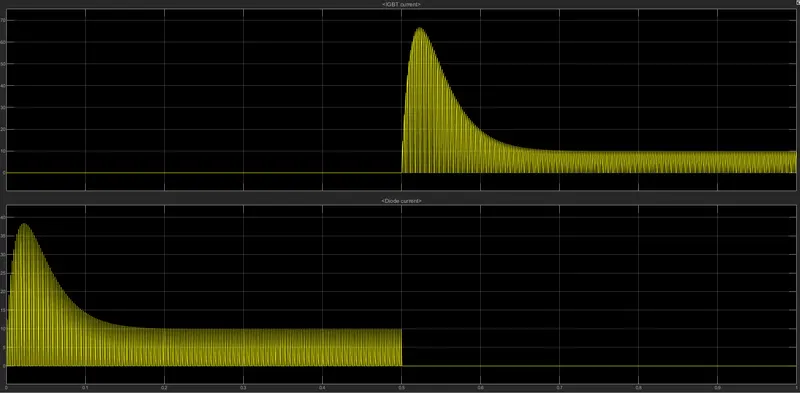
- Upto 0.5sec, Diode D3 is in Forward condition and Q3 is OFf and maximum current flows through diode D3 is 40mA.
- At 0.5sec, Q3 is ON and D3 is OFF, then Maximum current flows from Emitter to Collector is 70mA.
B) Armatue current
 .
.
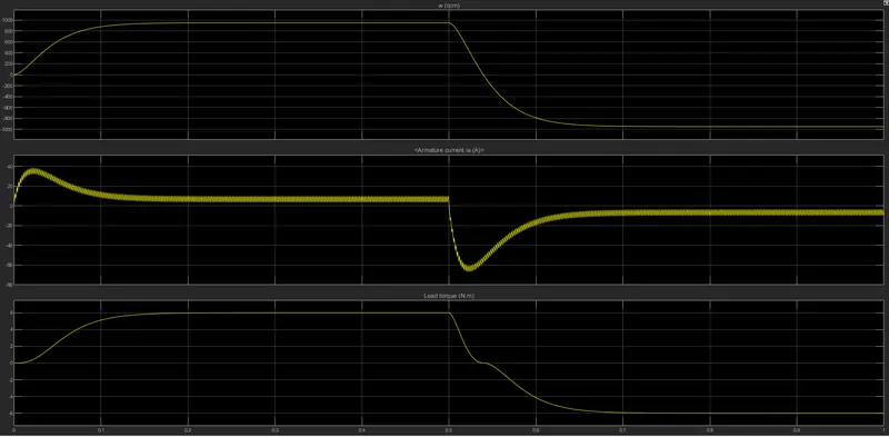
- Armature Peak Positive Current in motor is 40mA and it is gradually decreases to 10mAat 0.1sec and maintain constant upto 0.5sec. This Armature current is fluctuating due to high frquency pulse generator of 500Hz.
- At 0.5sec Due to sudden change in Armature voltage control switch current move to negative direction of peak current is -65mA upto 0.6sec and maintain constant current of -10mA.
- Motor Speed is 1000RPM upto 0.5sec and later on -1000RPM.
- Motor Torque is 6Nm upto 0.5sec and then -6Nm up to 1sec.
2.The Four-Quadrant Chopper DC Drive (DC7) block’. Comparing it with the H-bridge model
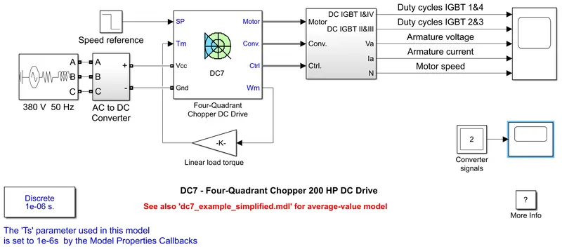
Schematic of Speed Controller and current controller
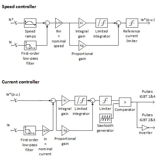
- The speed regulator outputs the armature current reference used by the current controller in order to obtain the electromagnetic torque needed to reach the desired speed.
- The speed reference change rate follows acceleration and deceleration ramps in order to avoid sudden reference changes that could cause armature over-current and destabilize the system.
- The current regulator controls the armature current by computing the appropriate duty ratios of the 5 kHz pulses of the four IGBT devices (Pulse Width Modulation). For proper system behaviour, the instantaneous pulse values of IGBT devices 1 and 4 are opposite to those of IGBT devices 2 and 3. This generates the average armature voltage needed to obtain the desired armature current. In order to limit the amplitude of the current oscillations, a smoothing inductance is placed in series with the armature circuit.
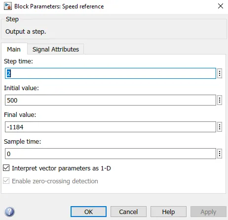
The input of the DC7 model is Speed Reference.which is given as follows
- Torque applied on DC7 block is linear Torque. Which is directly proportional to Speed of the motor
- Upto 2sec Motor Runs at 500RPM and later it runs in opposite direction of 1184RPM
Simulation Results:
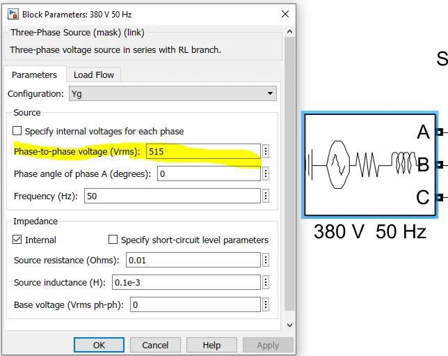
- set the initial bus voltage to 515 V.
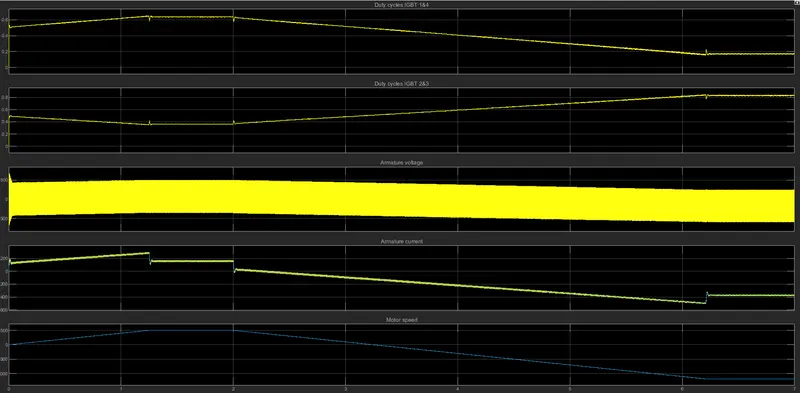
- Run the simulation for 7sec
-
At t = 2 s, speed reference drops to -1184 rpm. The current reference decreases to reduce the electromagnetic torque and causes the motor to decelerate with the help of the load torque.
-
At t = 2.2 s, the current reverses in order to produce a braking electromagnetic torque (dynamic braking mode). This causes the DC bus voltage to increase.
-
At t = 3.25 s, the motor reaches 0 rpm and the load torque reverses and becomes negative. The negative current now produces an accelerating electromagnetic torque to allow the motor to follow the negative speed ramp (-400 rpm/s).
-
At t = 6.3 s, the speed reaches -1184 rpm and stabilizes around its reference.
Comparision between BJT H Bridge and Four quadrant chopper DC7 block:
- Both are used to drive the DC Machine by controlling using semi conductors.
- Both are can operate in 4 quadrants
- In BJT H bridge Ripples and peak overshoot of Armature current are more.
- In DC7 block we use PI controller for speed of motor and current in motor so, that ripples are lesser compare to BJT H-Bridge and peak overshoot value also decreases. Drive runs with more stable.
- In DC7 block as PI controller is used, System Response is slower than BJT H bridge.
- DC7 block is nearer to real time situation and desired accurate results are obtained with less steady state error.
- In BJT H bridge direct DC supply is used to drive the DC motor, Whereas in DC7 block is given and converted to DC with Bridge rectifier.
2. Develop a 2-quadrant chopper using simulink & explain the working of the same with the relevant results.
- Two quadrant chopper which works on forward motoring and Regenerative braking modes.
Circuit Diagram: Two Quadrant Operation:
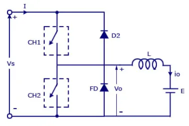
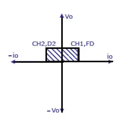
- As Shown in circuit diagram current flows in two directions across the load inductor from source to load and from load to source.
1.Source To Load:
- Whenever CH1 is ON Current flows in forward direction.
Direction of Current flow: (Vs+) - CH1 - L - E - (Vs-)
- When CH1 is OFF, the remaining Current in inductor flows through freewheeling diode by changing its inductor polarity in same direction until `V_L`>E.
Direction of Current flow:L - E - FD - L
Thus 1st quardrant operation is done.
2.Load To Source:
- When CH2 is ON current flows in Opposite Direction through CH2 When E>`V_L`.
Direction of Current flow: E - L - CH2 - E
- When CH2 is OFF Current flows back to battery source through D2.
Direction of Current flow: E - L - D2 - (V+) - (V-) - E
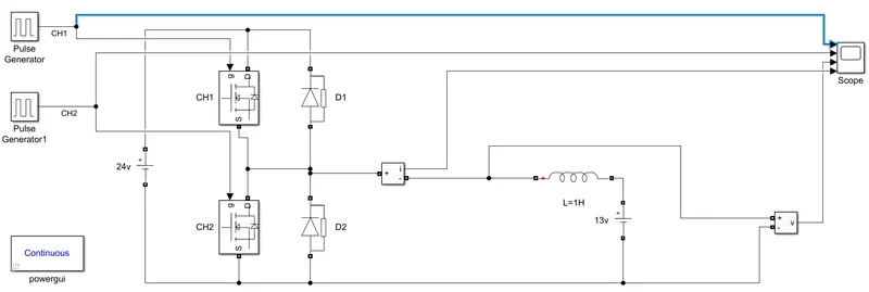
Simulink Model:
Simulation Results:
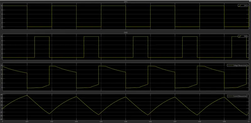
- At t=0sec, CH1 is ON , Hence Motor runs in forward direction and output voltage gradually decreases due to Back EMF and Drop across Inductor. Current increases Gradually.
- At t=0.01sec ,CH1 is OFF, the Remaining current in Inductor decreases linearly.
- At t=0.013sec CH2 is ON, the current Continous to flow in same direction ,At t=0.0161 current I=0 and current starts flow in reverse direction by the Back EMF source.
- At t=0.019sec , CH2 is OFF, then Current Starts Flowing through D2 to Voltage source and Voltage across load is Vo=Vs.
Thus By CH1,D1 motor wors in 1st quardrant and CH2,D2 motor works in 2nd quardrant.
3.Operation Of BLDC motor:
- BLDC: Brush Less DC motor.It is also known as electronically commutated motors (ECMs, EC motors).
- The Main Difference between Brush type and Brushless type is
- In Brushtype uses Chopper for working of motor
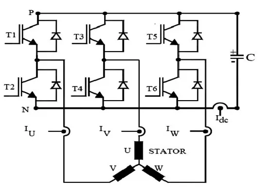
- In Brushless type uses 3-Phase Inverter for working of motor.
Construction:
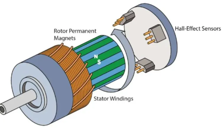
- Stator: A three phase BLDC motor has three windings. Each phase turns on sequentially to make the rotor revolve.
- Rotor: A rotor consists of a shaft and a hub with permanent magnets arranged to form between two to eight pole pairs that alternate between north and south poles.
- Hall Effect Sensor: This Sensor Triggers high whenever South Pole of rotor reaches to it and change the amplitude and direction of current in windings to rotate the rotor.
Types Of BLDC:
The layout of a DC brushless motor can vary depending on whether it is in “Out runner” style or “Inrunner” style.
-
Outrunner : The field magnet is a drum rotor which rotates around the stator. This style is preferred for applications that require high torque and where high rpm isn’t a requirement.
-
In runner : The stator is a fixed drum in which the field magnet rotates. This motor is known for producing less torque than the out runner style, but is capable of spinning at very high rpm.
Working:
- BLDC motor works on the principle similar to that of a Brushed Motor. The Lorentz force law which states that whenever a current carrying conductor placed in a magnetic field it experiences a force.
- As a consequence of reaction force, the magnet will experience an equal and opposite force.
- In the BLDC motor, the current carrying conductor is stationary and the permanent magnet is moving.
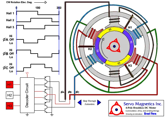
- The BLDC motor requires quasi-rectangle shaped currents fed into the machine. Alternatively, the voltage may be applied to the motor every 120°.
- Hall Effect sensor provides the portion of information needed to synchronize the motor excitation with rotor position in order to produce constant torque.
- It detects the change in magnetic field. The rotor magnets are used as triggers to the Hall Sensor.
- Three Hall Sensors placed 120° apart, are mounted on the stator frame. The Hall Sensor digital signals are used to sense the rotor
- The process starts when current flows through one of the three stator windings and generates a magnetic pole that attracts the closest permanent magnet of opposite pole.
- With the switching of windings as High and Low signals, corresponding winding energized as North and South poles. The permanent magnet rotor with North and South poles align with stator poles which causes the motor to rotate.
Advantages:
- Higher efficiency and reliability
- Lower acoustic noise
- Smaller and lighter
- Greater dynamic response
- Better speed versus torque characteristics
- Higher speed range
- Longer life