FINAL INDEPENDENT PROJECT
FORMULA 1 DESIGN CONSIDERING LATEST NORMS AND AERODYNAMIC FEATURES:
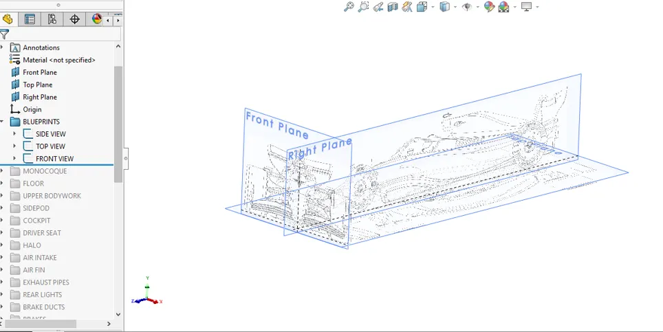
BLUEPRINTS:
MONOCOQUE:
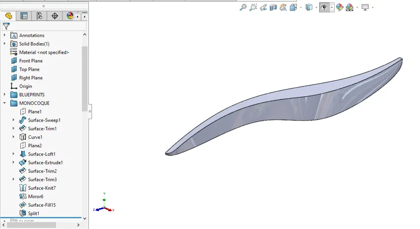
The foundational structure or chassis of a Formula 1 car comprises three key components: the Carbon Fiber Monocoque, Engine Block, and Transmission Enclosure. All other parts and elements are affixed to this central structure.
SUSPENSION:
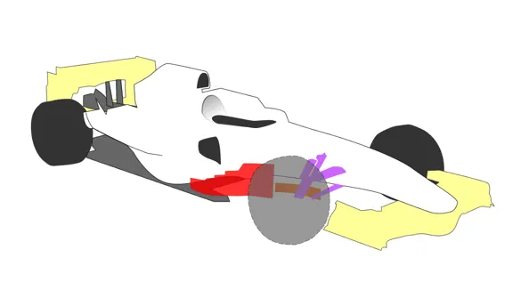
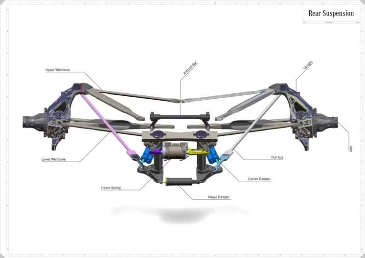
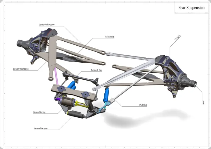
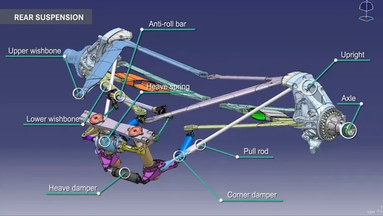
Formula 1 cars employ a sophisticated Double Wishbone suspension system, complemented by either a push or pull rod configuration for both the front and rear suspension setups. The choice between push rod and pull rod design varies among teams. The wishbones are connected to the chassis via flexural joints at the front and spherical bearings at the rear. While the front and rear suspensions share common components, their approaches differ.
For the rear suspension, F1 vehicles utilize a torsion bar and damper system. The independent sides of the suspension are linked to a roll bar, effectively curbing body roll during cornering manoeuvres. An additional component, known as the Heave spring and damper system, is integrated into the rear suspension. This system becomes crucial when both sides of the suspension move in tandem, particularly during acceleration and deceleration phases. Notably, the Heave system remains largely inactive under normal conditions. Moreover, meticulous design consideration ensures that suspension components boast an aerodynamic profile and are strategically positioned to minimize airflow disruption.
An F1 car’s suspension has an upper and lower wishbone – triangular-shaped carbon fibre bars that absorb the shock from the road – which essentially connects the chassis to the wheels.
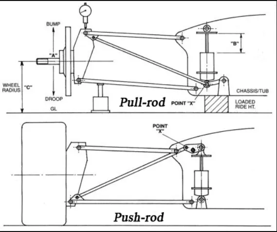
Between the wishbones, both at the front and rear, is a suspension rod – either a push-rod or a pull-rod – that connects the wheel to a horizontal torsion spring. The torsion spring stores and releases energy, while twisting when force is applied to it, and that helps to keep a car stable over bumpy surfaces.
A push-rod mechanism sits high up on the chassis where a diagonal rod then connects it to a low point of the wheel. So, over bumps or kerbs the wheel pushes on the torsion spring and that causes the push-rod to go upwards and towards the chassis.
That is the opposite to a pull-rod. A pull-rod mechanism sits low on the chassis where a diagonal rod then connects it to a higher point of the wheel. This means every time the car hits a bump or kerb, the wheel pulls on the torsion spring which causes the pull-rod to go up and outwards from the chassis.
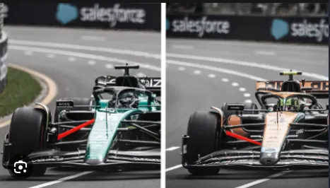
Both configurations have many advantages and disadvantages. It simply depends on what a team wants, because the suspension must fit the aerodynamic concept of the whole car as it plays a role in directing airflow towards the sidepod and other areas.
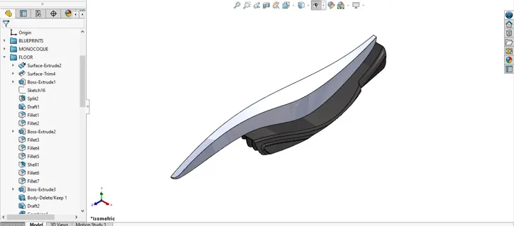
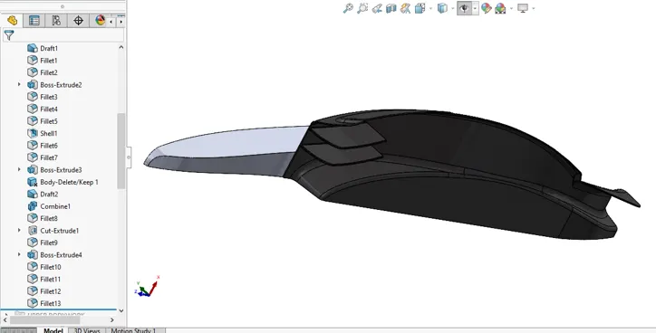
Floor- The car's floor plays a pivotal role in generating significant downforce by manipulating the airflow beneath the car relative to the airflow above. The floor design incorporates a rake, creating low pressures at the narrowest point between the floor and the track. The floor also guides airflow seamlessly through the diffuser, reintegrating it with atmospheric pressure behind the car.
The diffuser is engineered to channel the high-velocity airflow from beneath the car, while vertical vanes direct this air to merge with the upper airstream. Upon collision, this interaction generates a substantial amount of turbulent air behind the car, known as the wake.
The floor is designed to generate downforce and optimise airflow under the car. In this page, we take a closer look at the functions of an F1 car's floor and how it is designed. The floor of an F1 car has many functions. Its main purpose is to generate downforce and improve grip.
UPPER BODYWORK
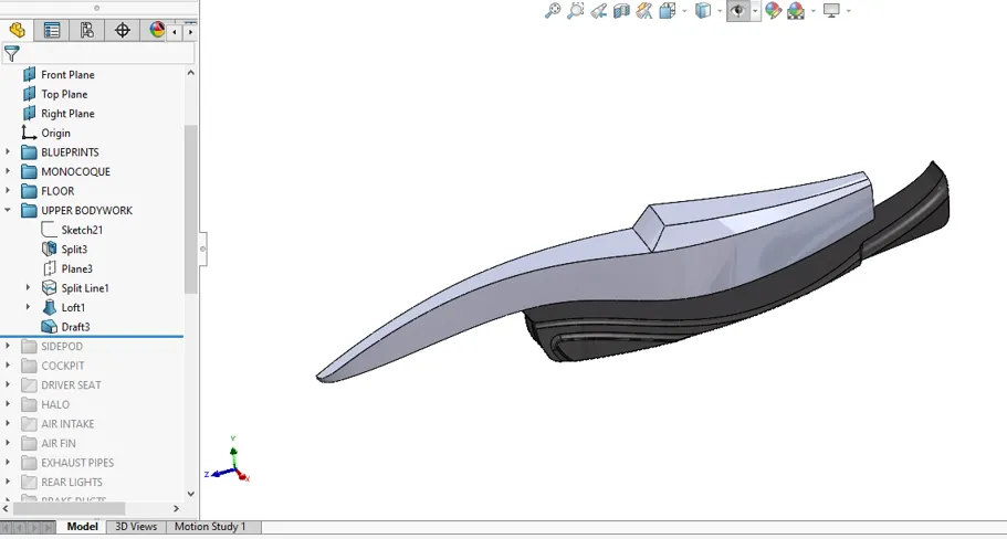
The bodywork and aerodynamic rules of F1 cars are described in Article 3 of the FIA Formula 1 regulations (there are a total of 22 articles in the current regulation, describing engines, wheels, crash tests... etc). Article 3 is used to describe where bodywork is permitted, and more recently, is used to define what sort of bodywork is permitted or outright required in certain places. As time has gone on, when teams have circumvented and subverted the intent of the regulations, or just to reduce speeds to improve the safety of the cars, the length of Article 3 has risen at a near exponential rate from 514 words in 1988, to over 10,000 words in 2021 (see below). It has been said that the 2022 regs will be the most prescriptive ever, and the Article 3 word count would seem to support that, rising to nearly 16,000 words with the next generation rules - that’s the sum of the 2011 and 2020 rules.
Below article as details on evolution of bodywork
https://www.f1technical.net/features/23219
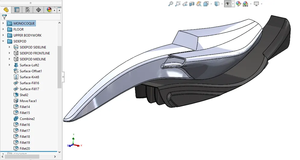
Side Pods- Clean air is channeled through the side pods, with the airflow exiting at the rear, primarily for cooling purposes. Radiators are positioned within both side pods.
Because the sidepods in simple terms, act a little bit like mini skirts. "Aerodynamically these wide sidepods help the suction in the floor. So that's the concept that it looks like you can't do without if you want to maximise the suction in the floor and the load on the car.
The main reason why the sidepods are so important is for their ability to manage airflow along the side, reducing drag and feeding air to the diffuser to improve the speed and overall drivability of the car.
COCKPIT:
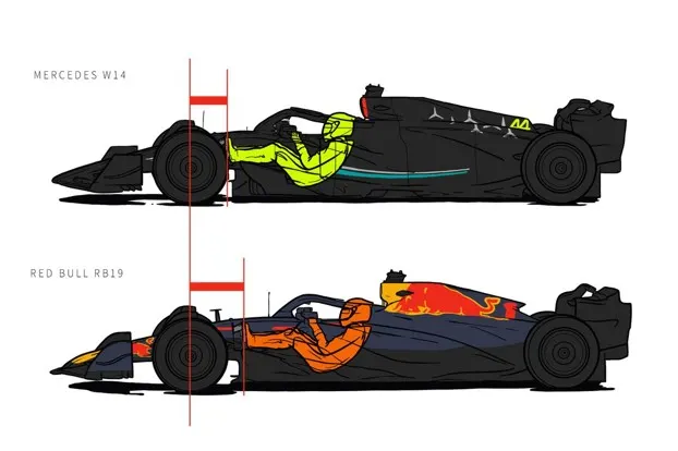
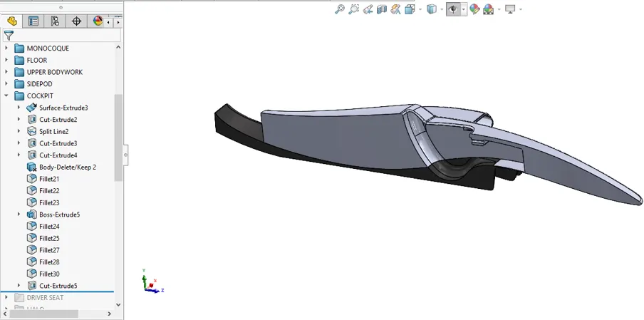
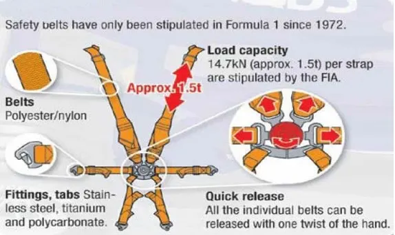
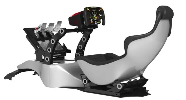
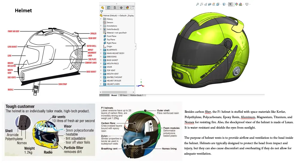
The F1 cockpit envelops the driver in a custom-molded seat tailored to individual dimensions. To secure the driver during high-speed maneuvers and potential accidents, a 6-point seat belt system is employed. A critical safety element, the Head And Neck Device (HANS), curtails excessive head movement both during races and in the event of collisions. HANS attaches to the helmet at two distinct points, firmly anchoring it to the driver's body via the seat belt.
Enhancing aerodynamic stability and airflow, the helmets are designed with front and rear spoilers.
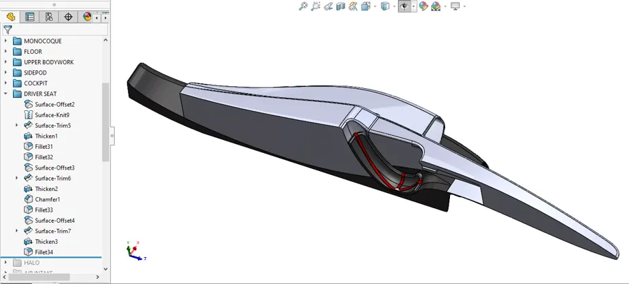
DRIVER SEAT
HALO
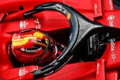
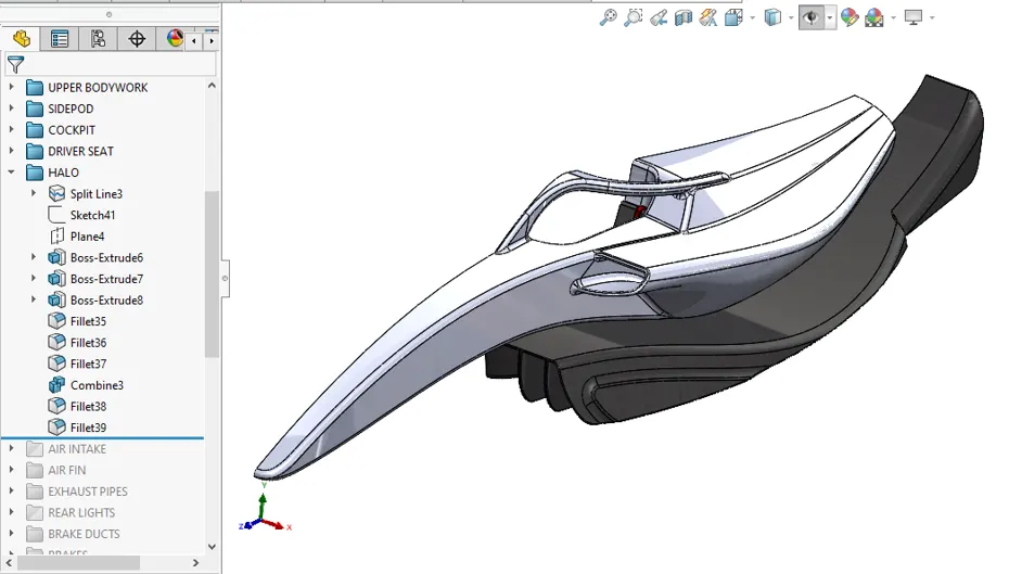
The Halo is a three-pronged tubular titanium structure that surrounds the cockpit of a Formula 1 car. It acts as a shield to deflect or absorb impact forces during accidents.
Also the rim of the cockpit is not much above eye level so the limits outward vision. The center post of the Halo is narrower than the space between their eyes so it doesn't cause blind spots. Hold Two fingers up between you and the tv screen. It appears that you can see right through your fingers.
AIR INTAKE
The air intake and airbox is one of the most distinctive features of a modern F1 car. Situated just above the driver's head, the oval-shaped air intake hole dictates not only the shape of the engine cover but also the flow of air into the engine.
The engine air intake on Formula 1 car is positioned behind and above the driver's head to capture high-pressure, relatively undisturbed air. Inside the air intake is an expansion chamber (diffuser) that slows the air down and thus increases its pressure ready for its passage into the engine inlet manifold.
One of the biggest drawbacks of a turbocharger is turbo lag — the time it takes for the engine to attain that precious burst of power. Since turbochargers often take longer to reach peak speeds than superchargers, there may be strategic value to choosing supercharged models
The delay between the driver's input on the throttle pedal and the engine's response is called turbo lag. Even though this delay typically lasts for only around a second, it causes an unpleasant experience for the driver.
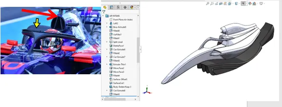
AIR FIN
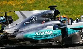
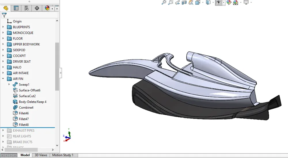
The fin creates a vortex from the cockpit that channels air directly to the wing, which would otherwise be lost, due to the cockpit blocking the wing from clean air. The fin can also act as a third mounting point for the rear wing, allowing for stronger material to be used, and greater overall wing stability.
EXHAUST PIPES
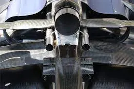
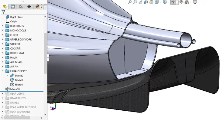
They're typically made from high-grade titanium or Inconel, a nickel-chromium alloy known for its heat resistance and durability. The exhaust system consists of a series of pipes that run from the engine to the car's rear, where the exhaust gases are expelled.
The wastegate is basically a valve that dumps the excess gases from the turbo into the air when the driver lifts the throttle and momentarily increases the pressures dumping the excess allows the turbine to run at a consistent speed without any dangerously high peak pressures.
One of the biggest drawbacks of a turbocharger is turbo lag — the time it takes for the engine to attain that precious burst of power. Since turbochargers often take longer to reach peak speeds than superchargers, there may be strategic value to choosing supercharged models.
One of the biggest drawbacks of a turbocharger is turbo lag — the time it takes for the engine to attain that precious burst of power. Since turbochargers often take longer to reach peak speeds than superchargers, there may be strategic value to choosing supercharged models.
REAR LIGHTS
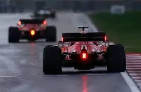
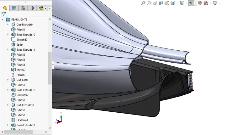
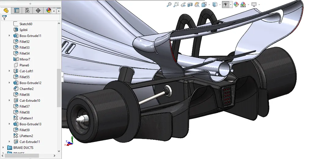
Quite simply, the light is there to alert drivers behind that a car is in front of them, like in a road car. Even light rain can be extremely difficult to drive in with all the spray flying up from the road as well as rain marks on the driver's helmet visor.
BRAKE DUCTS
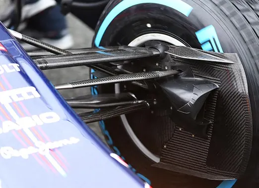
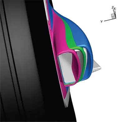
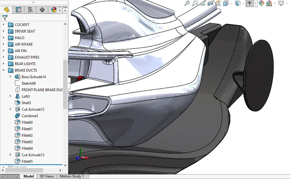
The brake duct brings in air to cool the temperatures down, but this also impacts aerodynamic performance. The bigger the air duct, the worse the impact on aero performance, but the more cooling that is gained.
Brake ducts lower disc temperatures by forcing more air through the internal disc vanes. That forced air is coupled with the centrifugal force generated by the spinning directional cooling vanes, drawing additional heat from the disc.
BRAKES
When you hit the braking point, you apply the brake pedal as quickly and as hard as possible, as the car slows, you gradually release the brake pedal and look for the apex. You turn the car in, still on the brakes and aim for the apex
Most of the time. Generally F1 brakes like to be hit hard, the ideal braking process is keep the car straight, brake 100% and then turn in. Braking any less than 100% in most scenarios means your leaving time on the table.
Braking is the first element in a Formula One car's cornering phase. If the car isn't slowed down at the right point and with the right pressure on the pedal, it will compromise the remaining phases - hitting the apex, taking the right line, carrying the optimum speed through the corner, getting the power down on exit and completing a clean run to the next turn. This can have a major impact on a driver's lap time.
Similar to a road car, the brakes on a Formula One car work on all four wheels. So how exactly does the system work?
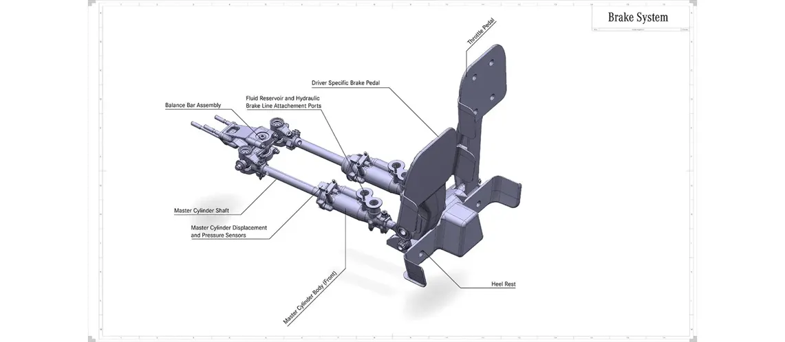
When the driver steps on the brake pedal, it compresses two master brake cylinders - one for the front wheels and one for the rear - which generate fluid pressure.
At the front, the system is very straightforward. The fluid pressure is delivered directly to the front brake callipers. Inside each calliper, six pistons clamp pads against the disc - and it is this friction that slows the car down.
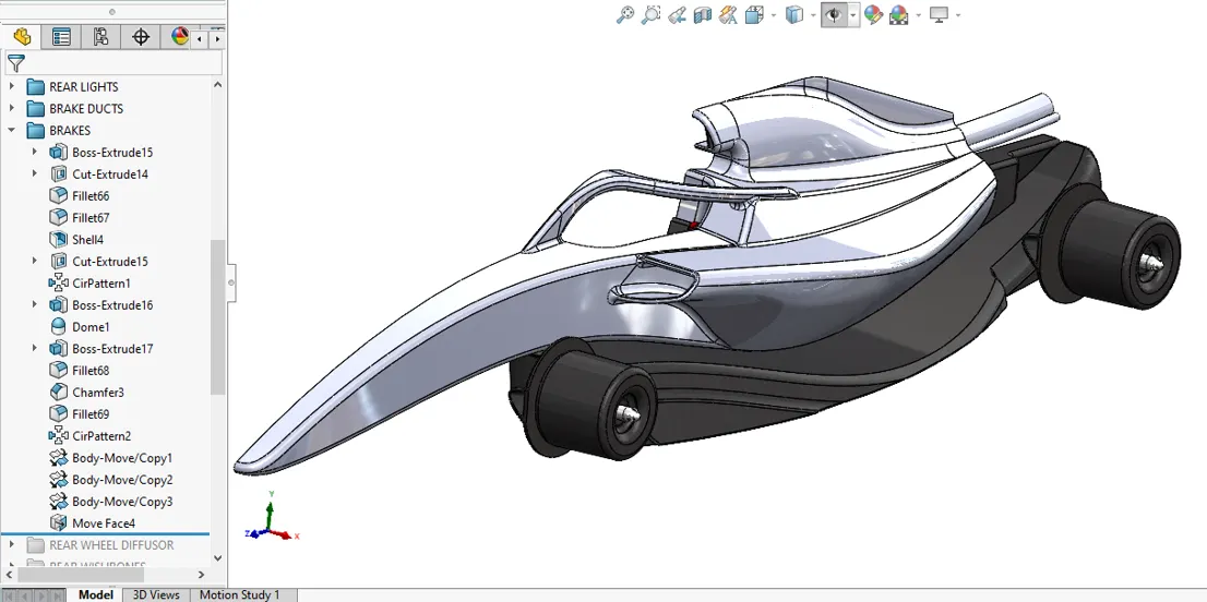
REAR WHEEL DIFFUSOR
Once the potential of using aerodynamic downforce to win races was realized, designers began experimenting with methods other than simply attaching inverted wings.
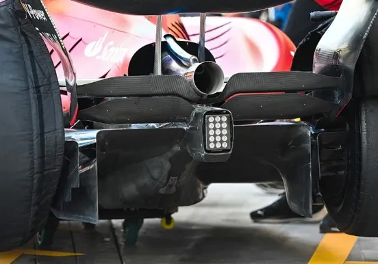
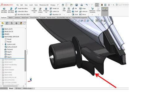
The diffuser is an area of bodywork at the rear of the car, although the term "Diffuser" is technically incorrect, it is the most popular term applied to this part of the car.
The air flowing below the car, exits through the diffuser on the rear of the car. The diffuser is usually find on each side of the central engine and gearbox fairings and is, by the rules, located behind the rear axle line. The diffuser creates nearly 50% of the cars downforce. Being so powerful the rules have progressively been tightened, making the diffuser smaller and smaller to cap cornering speeds.
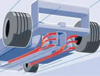
Although wings and diffusers work similarly, they are based on different concepts. A diffuser serves to eject air out from the underside of the car. This pulling action increases the velocity of the air below the car, so that the more slowly moving air above the car will push the car into the ground. The suction effect is a result of Bernoulli's equation, which states that where speed of the fluid is higher, pressure must be lower. Therefore the pressure below the race car must be lower than the pressure at the outlet since the speed of the air below the racecar will be higher than the speed of the air at the outlet.
The diffuser in itself doesn't produce a reduction in pressure. The role of the diffuser is to expand the flow from underneath the car to the rear, decrease the flow's velocity from inlet of the diffuser to outlet (so that at the outlet the flow velocity is similar to the free stream velocity), inturn produce a pressure potential, which will accelerate the flow underneath the car resulting in reduced pressure and as such, a desired increased downforce generation. This pressure difference is a function of the ratio of the areas at the inlet and the outlet of the diffuser, where this area ratio is set by the diffuser angle and the vehicle ride height.
Diffuser can be considered to have "pumped-down" the underbody, inducing a component of downward force on the vehicle.
It was found during testing that the diffuser actually acted as a pump to generate downforce over the underbody flow path. This was not deemed to be the only identifiable fluidmechanical mechanism affecting the flow path around the diffuser. The three main aspects were; "ground effect‟, "underbody upsweep‟ and "diffuser pumping‟.
- "Ground Effect" plays a role when an object is used in the vicinity of a moving ground. Flow asymmetry is developed from the flow accelerating as it travels underneath the body due to ground constraint as a result the static pressure underneath the body is reduced which provides the resulting downforce.
- "Underbody Upsweep" refers to the upsweep of the diffuser at the rear. This is typically cambered and up-curved in shape, similar to the upper surface of an airfoil. Due to the direction of this curving, a resulting downward directed lift force will result during flow interaction.
- "Diffuser Pumping" refers to the increased cross-section area over the diffuser length, which can be used to increase the flow rate through diffuser because of pressure potential. As the ratio of the inlet to outlet area becomes increasingly
greater, this generates greater pressure recovery that, due to the base pressure remaining constant will increasingly depress the base pressure at the inlet. The diffuser acts to reduce the underbody pressure due to the expansion resulting in increased flow rate under the body. This increase results in further decrease in underbody pressure, which produces the "pumping down‟. This scavenging both produces a lower pressure area under the car and also acts to reduce the boundary layer. This effect is reduced with the higher underbody heights regulated since the 90’s.
REAR WISHBONES
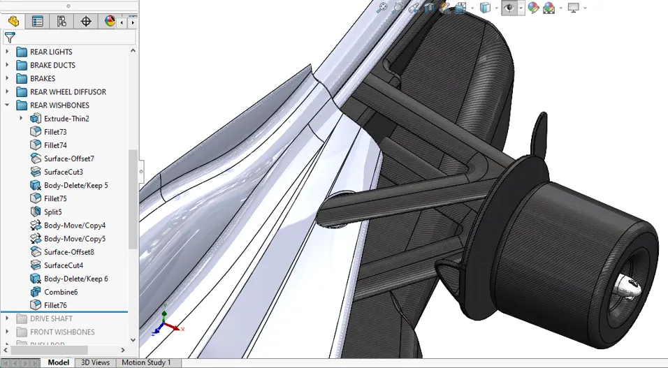
On a current F1 car, there are several points connecting the front wheels to the chassis. On the top and bottom, there are wishbones. The upper wishbone is normally shorter than the lower wishbone at the front of the car, leading to 'negative camber' – the tyres slope diagonally when they're stationary.
DRIVE SHAFT
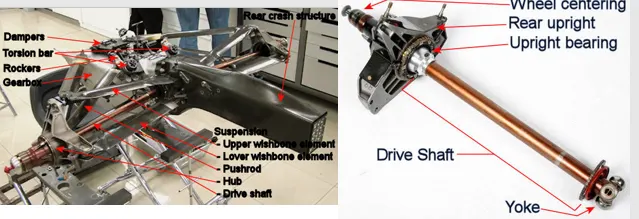
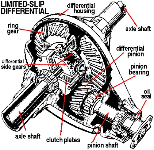
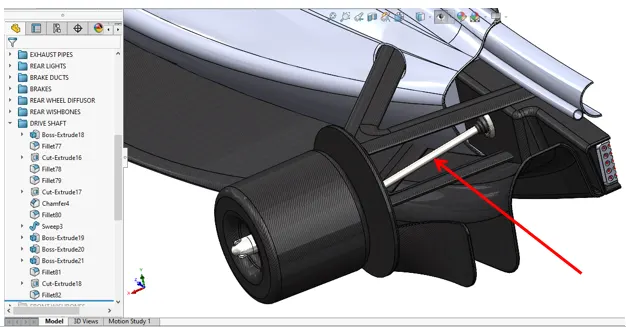
The drive shaft, some time called half shaft, is only link between the gearbox/differential and the rear wheel. The problem is that the common view about the drives haft is "it's a simple link". The fact is, while you can't gain horsepower through the drives haft, you can certainly lose it.
The drive shafts of Formula 1 racing cars are made of. carbon fiber, because the material is light and strong.
The drive shaft comes after the gearbox. It exists to transmit the torque (rotational force) provided by the engine to the wheels themselves in order to actually get the car moving.
FRONT WISHBONES
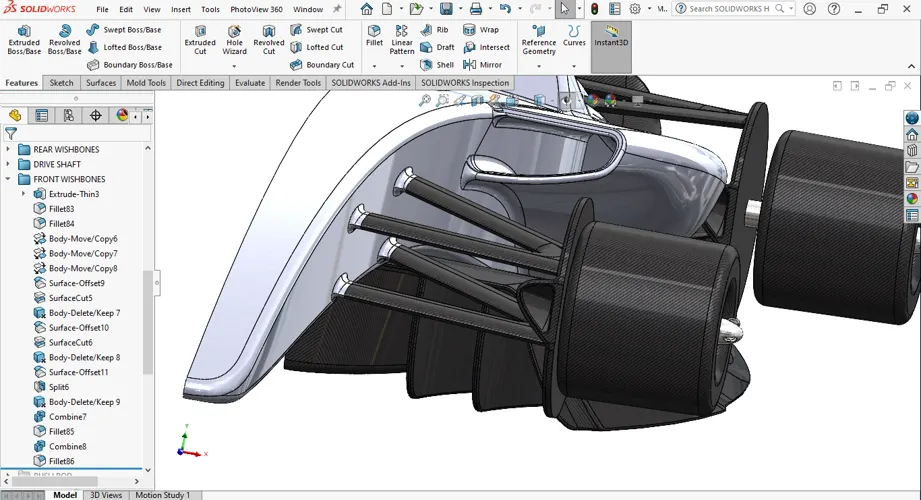
The function of the wishbone is mainly to take up horizontal forces, such as occur when accelerating or braking and cornering. Triangular wishbones are used in most SEAT models for the front wheel suspension and form a second, lower bearing of the vertical axis about which the steering movements are performed.
When an F1 car goes over a kerb at high speeds, the suspension needs to be strong and stiff to be able to handle those loads without occurring any damage. Carbon fibre elements such as the push rods and pull rods, for example, are very strong in compression and tension and can take loads of ten Kilonewtons or more.
PUSH ROD
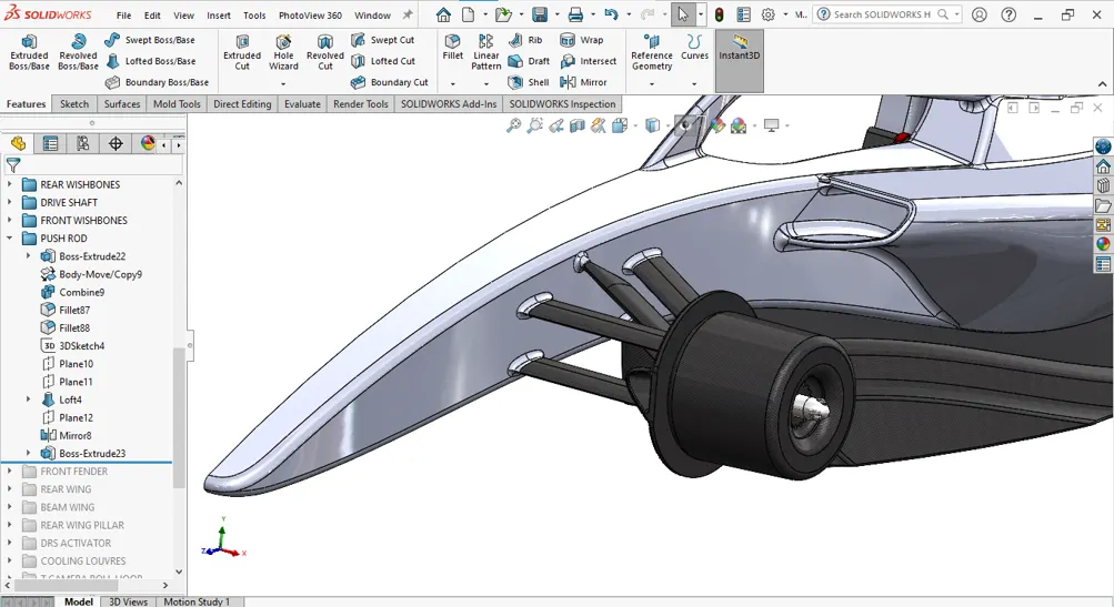
Push-rod suspension might make the springs and dampers easier to access as they're mounted higher up in the car, but other components might be harder to access as a result. Push-rod is also mounted higher on the car, increasing the car's centre of gravity.
A push-rod sits high up on the chassis where a diagonal rod then connects it to a low point of the wheel. So, over bumps or kerbs the wheel pushes on the torsion spring and that causes the push-rod to go upwards and towards the chassis. That is the opposite to a pull-rod.
FRONT FENDER
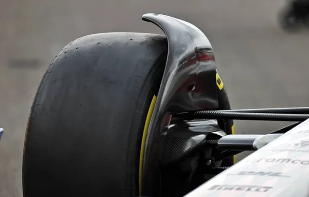
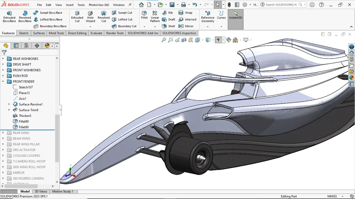
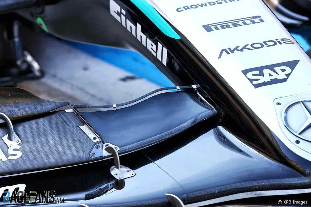
Each car has over-wheel winglets or shrouds, not mudguards or mud-flaps, as we Yanks refer to them.
This component’s job is to help control the air wake coming off the front tires and direct it away from the rear wing. Before the shroud, these air vortices went from the front wing. These are sensitive in close quarters battles as the shroud is less susceptible to getting ripped off by a wheel or curb. The shroud is more resilient to damage during a good battle and achieves the same result as previous components on the front wing.
Formula One is doing all that it can to reduce the chaotic airflow coming off the car during cars following each other closely. Stable airflow allows the cars to closely follow each other without losing downforce in the wake of the lead car.
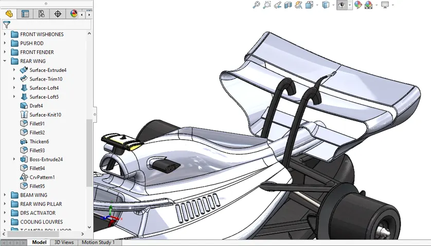
Rear Wing- The rear wing plays a critical role in generating downforce through its upward-sloping design. The wing's end plates feature notched designs with various contours, aiding in directing wing tip vortices away from the car.
However, like downforce, the rear wing also contributes to drag. To address this, Formula 1 cars are equipped with a Drag Reduction System (DRS), which the driver can deploy to achieve higher straight-line speeds, especially during overtaking maneuvers. Hydraulic actuators in the wings open a section of the wing, allowing air to pass through and reducing drag, resulting in an extra speed boost of around 10-12 km/h.
BEAM WING
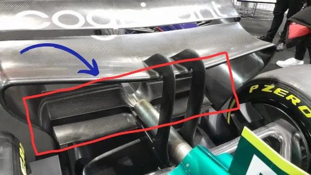
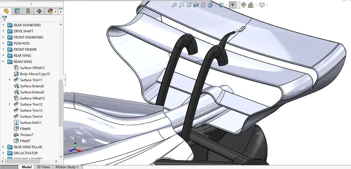
Beam Wing. A single element wing at the lower part of the rear wing that helps regulate the air below the upper rear wing sets and improves diffuser performance. As F duct mounted on the upper flap is banned, there is now more aerodynamics consideration taken into the beam wing design.
First, it creates downforce by redirecting air that passes under the car, which helps to increase traction and stability during cornering. The beamwing also helps to control the airflow over the rear of the car, which can improve aerodynamic efficiency and reduce drag.
The rear beam wing works by redirecting the airflow, air passing over the rear of the car and creating a high-pressure area above the wing and a low-pressure area below it. Pressure differences produce downforce
REAR WING PILLAR
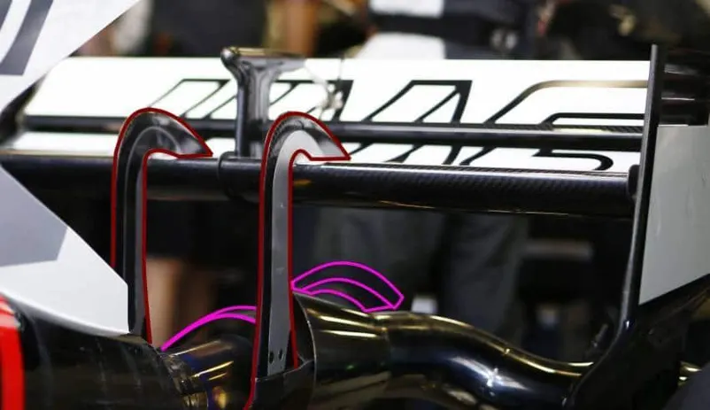
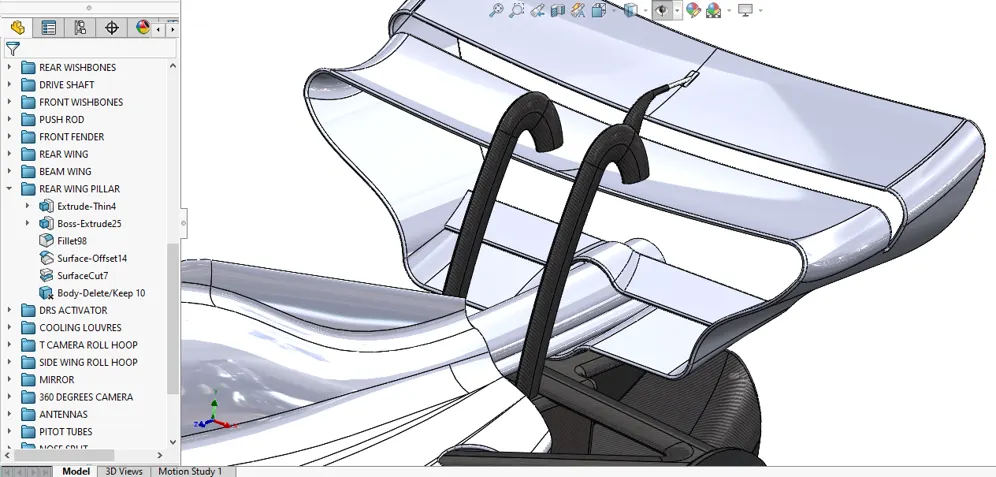
The rear wing is positioned at the back of the car and creates a wake that flows over and around it, reducing the air resistance or drag. The rear wing is also adjustable, which allows the driver to optimize the car's stability and speed on different tracks.
DRS ACTIVATOR
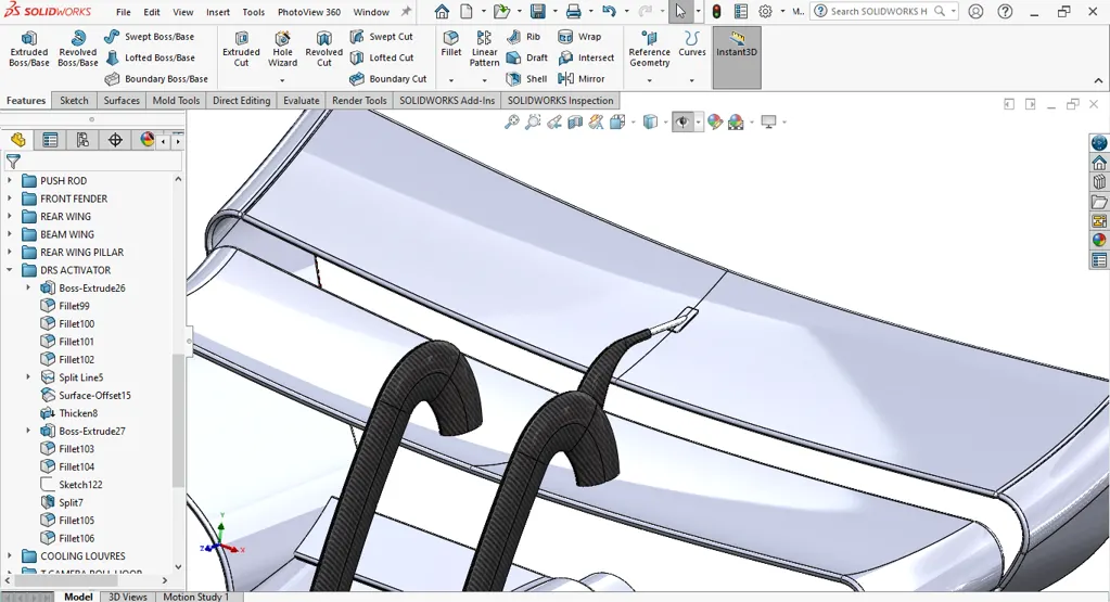
When can DRS be used in F1? In Formula 1, DRS (Drag Reduction System) can be used in designated DRS zones on certain parts of the track during qualifying and the race. To activate DRS, a driver must be within one second of the car ahead at a specific detection point before the DRS zone
The term stands for drag reduction system, a controversial mechanism controlled by the driver. With the press of a button in specific zones the rear wing can open on F1 cars. DRS facilitates closer racing and helps with overtaking as the rear wing's flap opens up, reducing drag to increase speed.
But DRS is not a simple ‘overtake button’ that automatically means getting past the car in front. While there have been plenty of occasions where its power has been deemed to be too great and so passes have occurred well before braking zones on straights, the tool is generally aimed at assisting overtaking when drivers would otherwise be stuck in dirty, turbulent air
However, as the latest generation of F1 cars have been designed to allow drivers to follow more closely with a reduced ‘dirty air’ effect, many people had hoped this would lead to DRS being dropped. While that is an aim of F1’s sporting bosses in the coming years, the device’s continuing usage remains disputed.
Since wing-produced aerodynamics became an integral part of F1 car performance in late 1960s this has had a direct effect on how closely the cars are able to follow each other.
COOLING LOUVRES
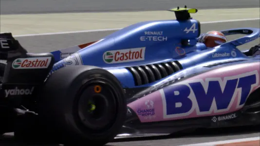
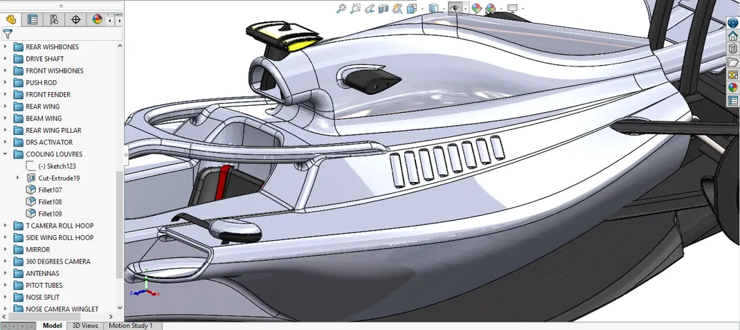
A shoulder louvre is used for ventilation and is a slatted panel used to help airflow move around the car and help keep the engine cool. It is so named a 'shoulder' louvre based on its positioning on the car - mounted on the shoulders of the engine. The slats or vents are angled to increase the speed of the airflow.
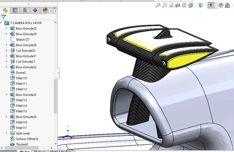
T CAMERA ROLL HOOP
A T-Cam is a small camera that is mounted on a T-shaped bracket on top of the car. It is one of the several onboard cameras that are used to film the race from different angles and perspectives.
The roll hoop of a Formula 1® car provides a critical part of the overall safety cell for the driver. Mounted at the top of the chassis, behind the driver's head, the roll hoop must support the weight of the car during a rollover accident and protect the driver's head.
The main purpose of the T-Cam, however, is to provide data and telemetry for the teams and the FIA. The T-Cam is connected to a transmitter that sends information such as speed, position, lap time, tire temperature, fuel level, brake pressure, and engine mode to the team's garage and to the FIA's race control. This data is essential for the teams to monitor their performance and strategy, and for the FIA to enforce the rules and regulations.The T-Cam is also equipped with a GPS system that tracks the location of each car on the circuit. This allows the teams to see where their rivals are on track, and to plan their pit stops accordingly. The GPS system also enables the FIA to implement virtual safety cars (VSC) and delta times, which are used to slow down the cars in case of an incident without deploying an actual safety car.The T-Cam is therefore a vital piece of technology that enhances both the racing and the viewing experience of Formula 1. It offers a unique perspective of the cars and their drivers, while also providing valuable data and information for analysis and decision making.
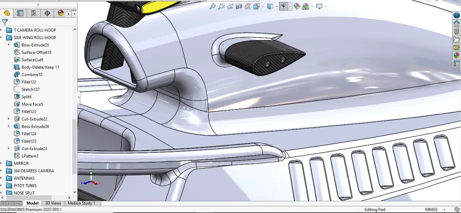
SIDE WING ROLL HOOP
The series installs 23 to 28 trackside cameras at each race, another 10 in the pit lane, and has a camera in a helicopter to capture aerial shots. These are complemented by small cameras on every car, facing forward, backward and looking at the face of the driver in the cockpit.
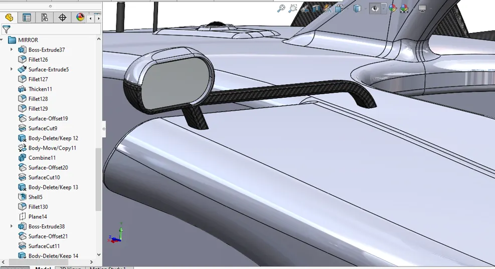
MIRROR
Do F1 cars have rear view mirror? Ofcourse all race cars and rally cars need a rear view mirror/side view mirror. they will have one of the 2 as they need to see the car following them to avoid impact around corners and yet maintain their speeds and braking paces.
Revised mirrors to improve driver visibility. In an attempt to increase driver visibility, there will be a change to rear-view mirrors on F1's 2023-spec cars, with the width of the reflective surface increasing by 50mm from 150mm to 200mm.
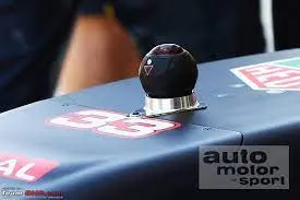
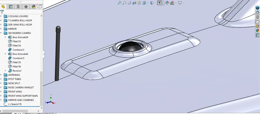
360 DEGREES CAMERA
ANTENNAS
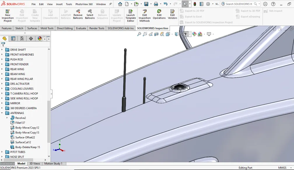
The larger one is a radio antenna. The smaller one in front is a stack of pitot tubes. These are used to measure local airspeed and direction, which can then be used in conjunction with suspension load cells to measure and correlate downforce and aero balance with the incoming flow conditions.
The antenna converts the electric current to radio waves that are transmitted out in all directions. A receiving antenna intercepts EM waves transmitted through the air. From these waves, the antenna generates a small amount of current, which varies depending on the strength of the signal.
PITOT TUBES
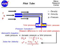
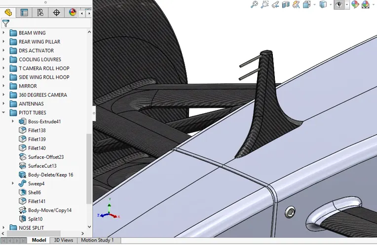
Pitot tubes were invented by Henri Pitot in 1732 to measure the flowing velocity of fluids. Basically a differential pressure (d/p) flow meter, a pitot tube measures two pressures: the static and the total impact pressure.
Pitot tubes are most commonly found in aeroplanes where they are used as speedometers. In an F1 car, a pitot tube measures the speed of wind flowing over the top of the car. This measurement is affected by wind speed, wind direction, speed of the car, and the position of the Pitot Tube on the car.
NOSE SPLIT
NOSE CAMERA WINGLET
FRONT WING
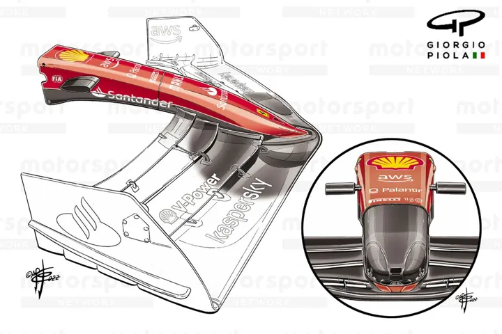
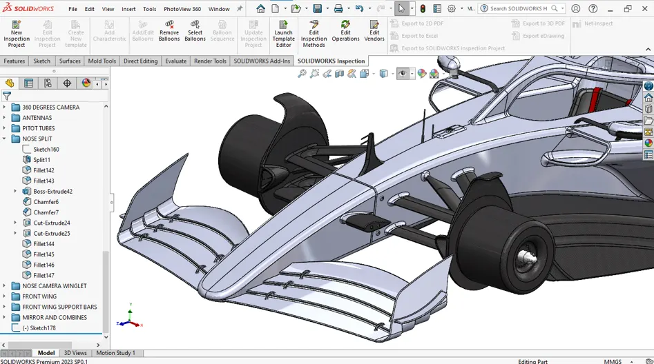
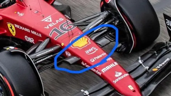
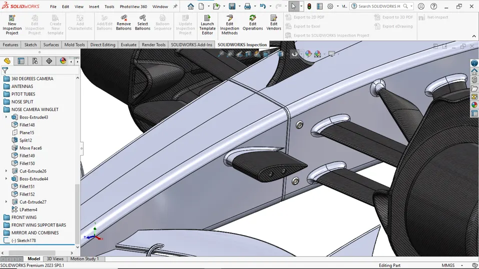
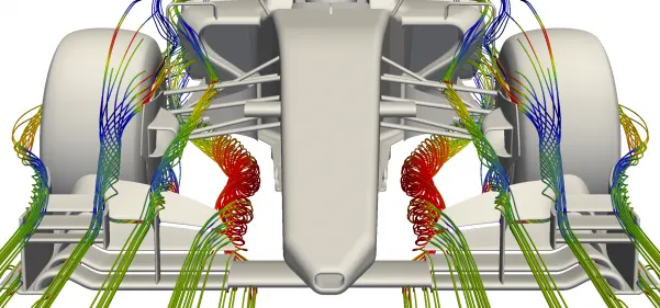
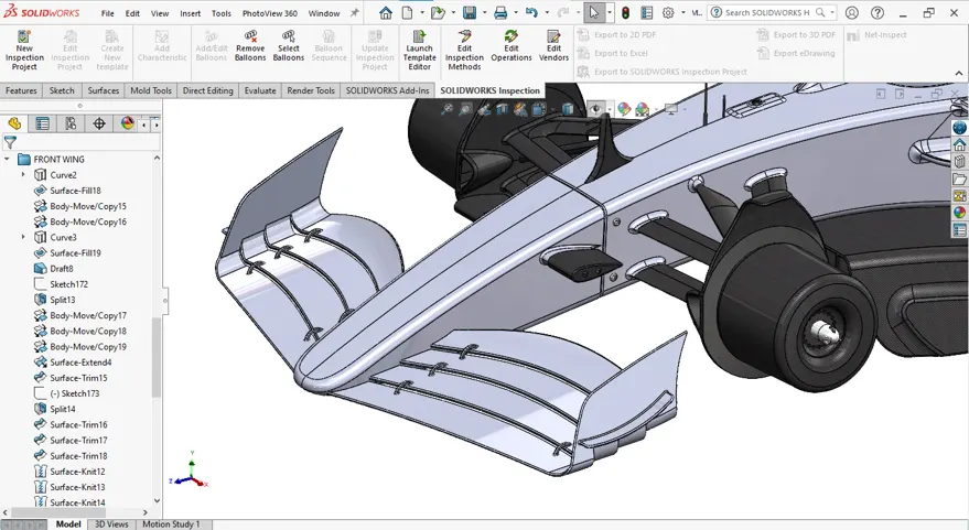
The front wing of a Formula 1 car operates in a manner opposite to that of an airplane wing. While aircraft wings generate lift, the F1 car's front wing creates downforce, which pushes the car onto the track. As air flows over the wing, it creates a high-pressure area above and a low-pressure area below, resulting in a net force that enhances traction. At the wing's edges, the upper and lower airflows interact, generating vortices (turbulent air) that contribute to drag. To mitigate this effect, the front wing is equipped with end plates, akin to winglets seen on commercial aircraft. The central section of the wing curves inward intentionally, producing vortices directed beneath the car, effectively sealing clean air beneath the vehicle.
FRONT WING SUPPORT BARS
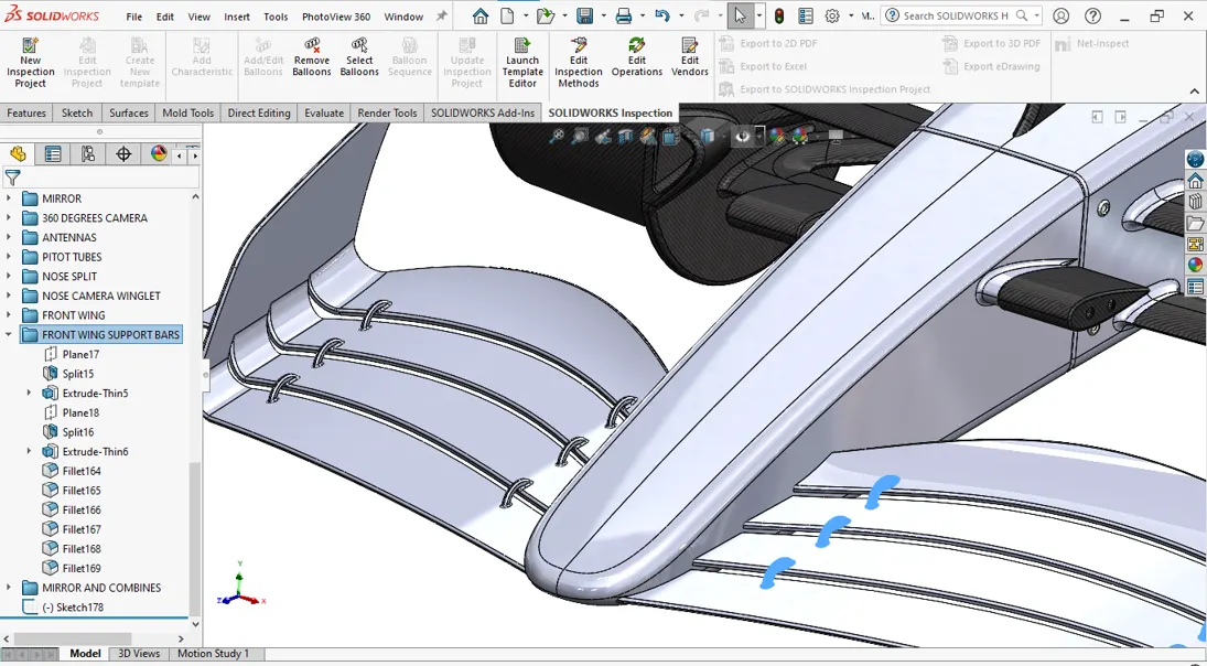
The front wing works in the opposite way of how an aircraft wing works. While an aircraft wing produces lift, the front wing produces downforce to keep the car from taking off. In other words, the airfoil of a front wing is profiled so that it helps keep the car on the ground and wheels in contact with the surface.
A straight, unswept wing experiences high drag as it approaches the speed of sound, due to the progressive buildup of sonic shockwaves. Sweeping the wing at an angle, whether backwards or forwards, delays their onset and reduces their overall drag.
STEERING WHEEL
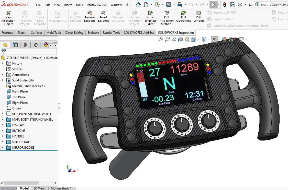
An F1 car does not have a clutch pedal controlled by the driver's foot, instead, such cars have a clutch paddle located on the steering wheel. Formula 1 cars have semi-automatic transmission and a clutch that works electro-hydraulically.
Paddle shifters are mechanisms built into the back of a car's steering wheel or on the steering column that actuate the car's gears. The right paddle upshifts, while the left paddle downshifts. In certain vehicles, both the left and right paddles are designed to shift up or down for maximum flexibility.
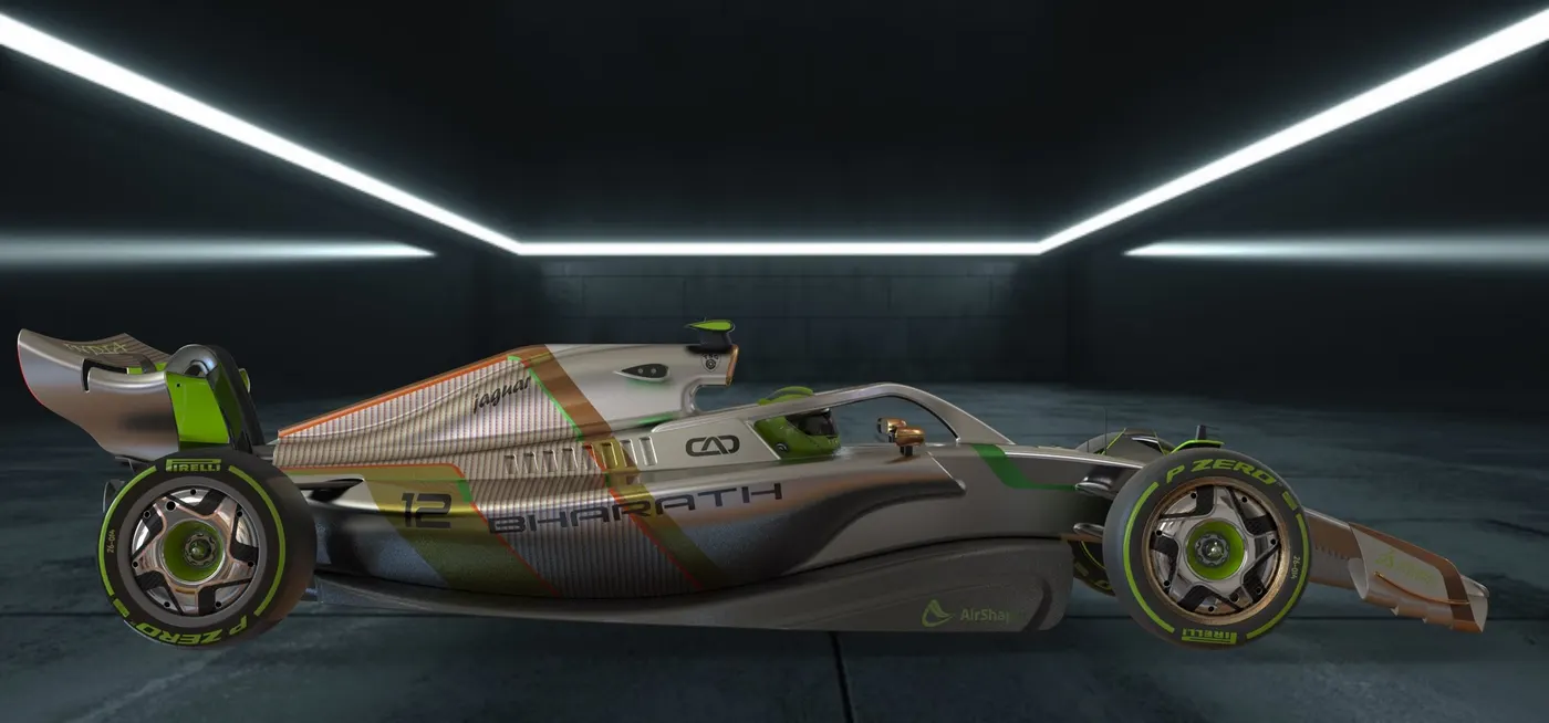
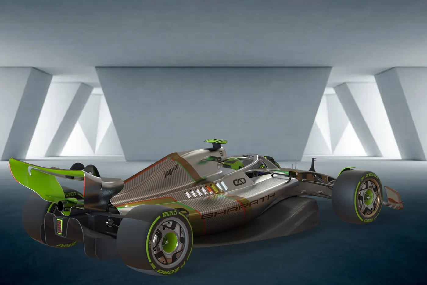
NOTE: CAD FILES AND RENDERING FILES LINK PROVIDED IN THE PPT .