FINAL INDEPENDENT PROJECT
MBD Of Four Bar Mechanism Using Solidworks
AIM
The aim of this project is to analysis the kinematic properties of piston crank assembly using motion analysis in solidworks.
OBJECTIVE
- To understand about the four-bar mechanism used in engines
- To analysis the kinematic properties of number of links used in this project.
- To understand about how the rotational motion transfer into linear motion.
THEORY
A slider-crank linkage is a four-bar linkage with three revolute joints and one prismatic, or sliding joint. The rotation of the crank drives the linear movement the slider, or the expansion of gases against a sliding piston in a cylinder can drive the rotation of the crank.
There are two types of slider-cranks: in-line and offset.
In-line: An in-line slider-crank has its slider positioned so the line of travel of the hinged joint of the slider passes through the base joint of the crank. This creates a symmetric slider movement back and forth as the crank rotates.
Offset: If the line of travel of the hinged joint of the slider does not pass through the base pivot of the crank, the slider movement is not symmetric. It moves faster in one direction than the other. This is called a quick-return mechanism.
SETUP
It is a simple design and setup but the output result is most important and also this mechanism should be known by everyone. Therefore, the following three-part files are created separately with simple dimensions. Then all the part files are assembled together and finally achieved the motion analysis of this four-bar mechanism.
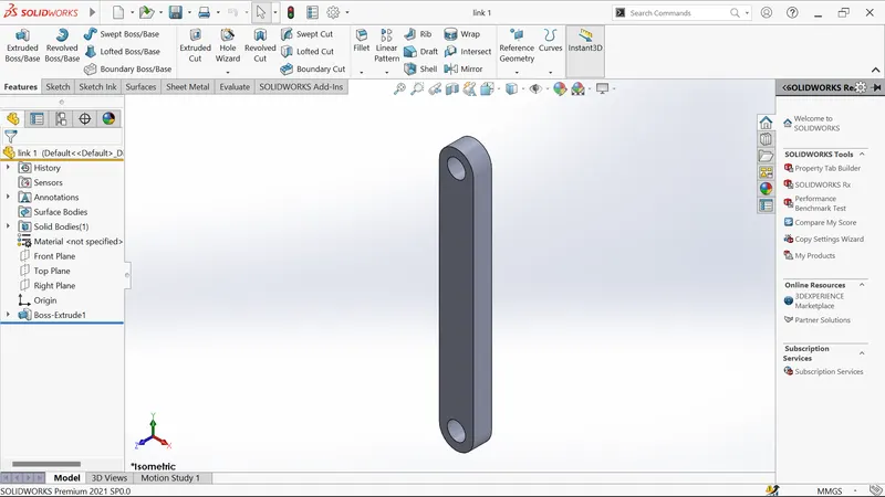
(i)link 1: it is act as a crank in engines. The input speed of 10rpm is given to this one of the hole axes. So, it rotates about that axis with constant speed of 10rpm.
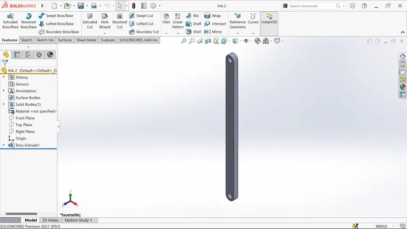
(ii)link 2: it is act as a connecting rod in engine. It’s one of the hole axis is concentric with another hole axis from link1.
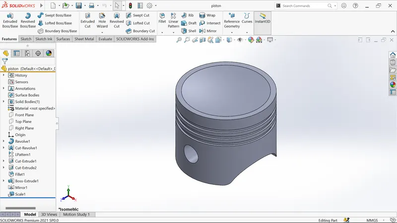
(iii)piston: here we can see that output result that means linear displacement after proper mates are given to all the components.
RESULT
As I mentioned in the aim of this project the following plots are obtained. This will help for everyone clearly about this four-bar mechanism.
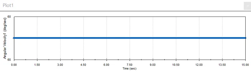
(i)Angular velocity of link-1
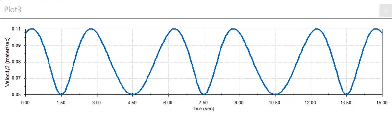
(ii)linear velocity of link-2
RESULT
So, from the first plot we can clearly understand the constant angular velocity that is 60deg/sec. because I assigned the input speed of 10rpm.
Also, from the second plot we got the linear velocity of link2. It comes like a sin wave. The linear velocity in trough is differ instead of the linear velocity in crest is same. During the forward stroke link1 and link2 meet in straight. So the velocity suddenly decrease in that position.