Fender Design - Wheel Arch Challenge
Wheel Arch Challenge
Aim:
Calculate the Wheel Arch gap at required points and check whether the car passes the European standard.
Objective:
- Study different wheel arch gap standards.
- Measure the wheel arch gap at specified points.
Wheel Arch:
The wheel arch is the semicircular part positioned above the wheel of a vehicle. The wheel arch is designed in such a way that it protects both the pedestrian and the vehicle cabin from mud, water stones and other road spray.
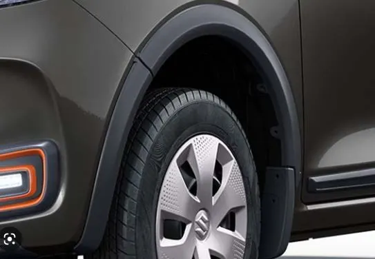
FIGURE: 1 WHEEL ARCH
Wheel Arch Regulations Requirments:
Japan Requirments:
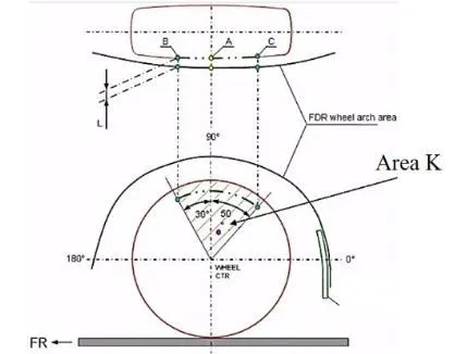
FIGURE: 2
'L' is the clearance between tyre, hub, cap and fender in area K.
Clearance 'L' must be greater than 5 mm in all three positions.
Also we have to measure the wheel guard requirment, defined by 'a'. For Japan requirments it is more than 5 mm at a line of 30 degree forward and 50 degree rearward from the central vertical axis of axis of wheel.
European Requirments:
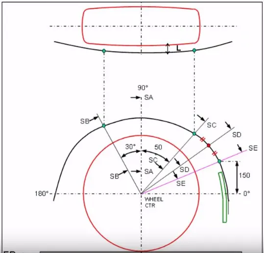
FIGURE: 3
'L' is the clearance at sections SA-SA, SB-SB, SC-SC, SD-SD, SE-SE.
Clearance 'L' must be greater than 10 mm in the five sections mentioned above.
For wheel guard requirment the 'a' is more than 5 mm at a line of 30 degree forward and 50 degree rearward from the central vertical axis of axis of wheel.
US Requirments:
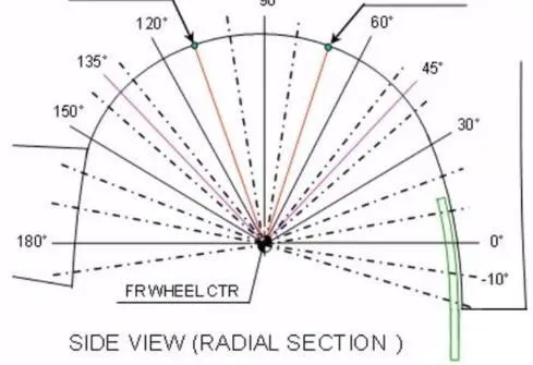
FIGURE: 4
Clearance 'L' is to be checked at all positions from -100 degree to 100 degree and create clearance check chart to validate.
Clearance 'L' must be greater than 5 mm in all three positions.
Also for wheel guard requirment 'a' is more than 5 mm at a line of 30 degree forward and 50 degree rearward from the central vertical axis of axis of wheel.
Wheel Arch calculation as per European Reglations
For calcultion the wheel arch we have to create a datum plane on the outer face of the given wheel part model. After that we have to draw some refrerence lines on the datum plane and give the required angle as per european regulations for measurement the wheel arch gap. We take Fig._3 as a reference.
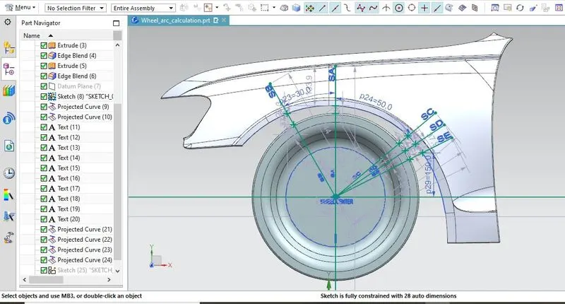
FIGURE: 5
After that I'm adding text on reference lines. Then I'm creating the intersection point between the reference line and the wheel arch for measuring the wheel arch gap.
Then I measure the gap and the results are given below.
For 'a' values
- SB = 44.7577 mm
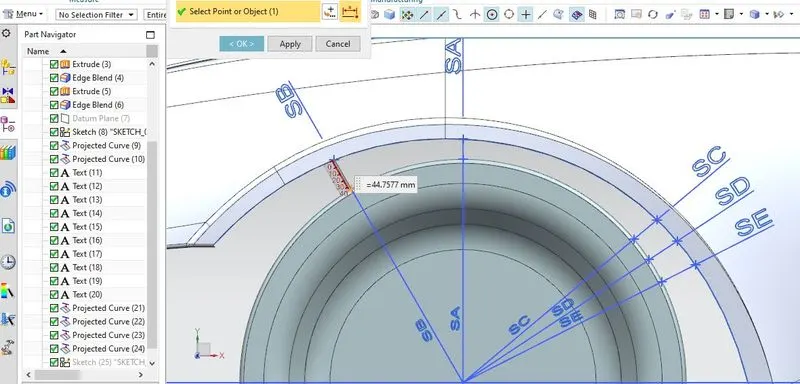
FIGURE: 6
- sc = 38.3597 mm
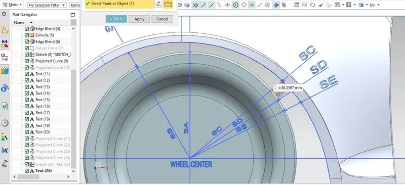
FIGURE: 7
For 'L' values
- SB - SB = 10.0000 mm
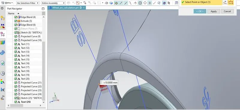
FIGURE: 8
- SA - SA = 9.9490 mm
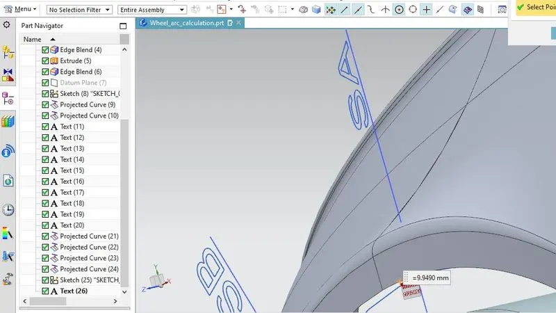
FIGURE: 9
- SC - SC = - 0.113949 mm
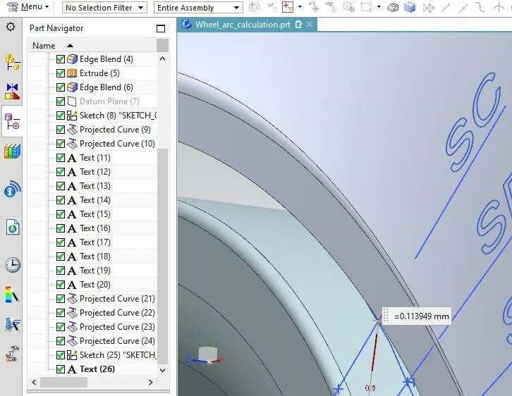
FIGURE: 10
- SD - SD = -2.8875 mm
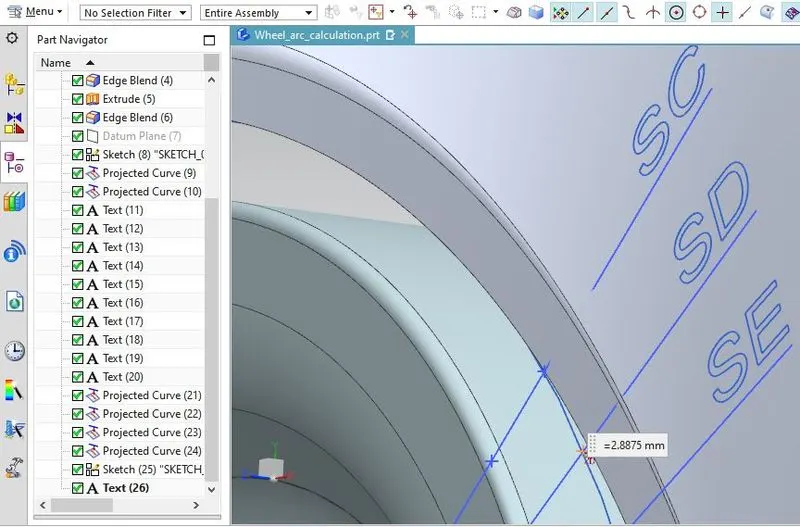
FIGURE: 11
- SE - SE = -5.9973 mm
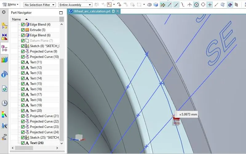
FIGURE: 12
Now the results are tabulated which is given below
For European Standards:
- 'a' is more than 5 mm at a line of 30 degree forward and 50 degree rearward from the central vertical axis of axis of wheel.
- Clearance L must be greater than 10 mm at sections SA - SA, SB - SB, SC - SC, SD - SD, SE - SE.
Tabultion Chart:
| SECTION | L (> 10 MM ) | RESULT | a (> 5 MM ) | RESULTS |
| SB - SB | +10 | PASS | 44.7577 | PASS |
| SA - SA | +9.9490 | FAIL | ||
| SC - SC | -0.113949 | FAIL | 38.3597 | PASS |
| SD - SD | -2.8875 | FAIL | ||
| SE - SE | -5.9973 | FAIL |
Conclusion :
From the above results we can conclude that the wheel arch gap does not meet the requirments of European regulations as the minimum clearance between the wheel arch to the outer most wheel (tyre) is 10 mm in all five sections.
So, we can not consider this design for further process. We have to work on it to meet the requirments of European regulations.