Fender Design - Wheel Arch Challenge
Aim: To analyze the WHEEL ARC of the FENDER according to the requirements of different nations.
Fender:
- The main purpose is to prevent sand mud rocks liquids and road spray from being thrown into the air by the rotating tire.
- Prevent injuries for pedestrians from all the chips and rocks from tires.
- It also covers the engine compartment.
Wheel Arc:
- The shaped part of the bodywork of a car or other vehicle that allows the wheel to be accessed, and in the case of front wheels, enables them to be steered.
Design requirements for the Wheel arc:
When it comes to wheel arc different Nations have different standards and in our case, we consider 3 of them they are
- Japan
- European
- United States
Japanese Regulations requirements for fender design:
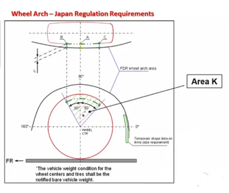
- According to the Japanese Regulations requirements for the fender design there should be a 5mm or above gap between the wheelbase and the fender at three different points as mentioned below
- The three different points are the intersecting points on the projected curve of the fender and the lines that are drawn at an angle of 30deg, 50deg from the perpendicular lines, and the perpendicular line itself which is drawn from the center by making the outermost layer of the wheel as a datum.
- Wheel guard requirement: The value of 'a' shall be more than 5 mm at line 30 forward and 50 rearward from the central vertical axis of the wheel.
European Regulation Requirement:
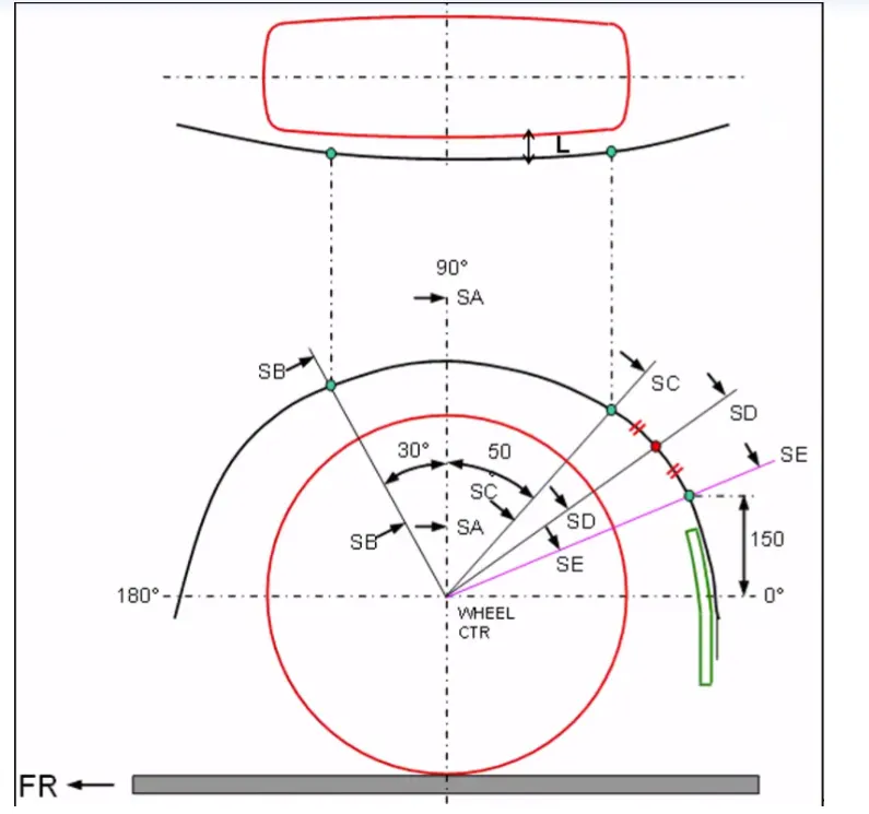
- In addition to the japan requirement here they have added 2 more inspection points and the minimum gap is increased to 10mm or above.
- The two points are the intersections points of the fender arc and the line drawn 150mm away horizontal line from the origin point of the wheel circle and a line that is drawn at the center to the previous line and the 50deg angle line.
US Regulation Requirement:
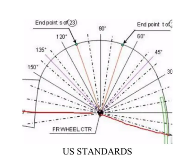
- In the above 2 cases they ask for 3 or 5 only but in this case, they ask for every intersection point of the wheel arc and the line at every 10 degrees where the line starts at -20deg to 180deg.
- As per US Regulation Requirements the clearance gap should be 5mm or above.
Note: Taking into Consideration of the above 3 nations if we have to design a car fender we can take the maximum value of clearance among the 3 So the max is 10mm or above.
Design Part:
- Drawn the line as per the requirements
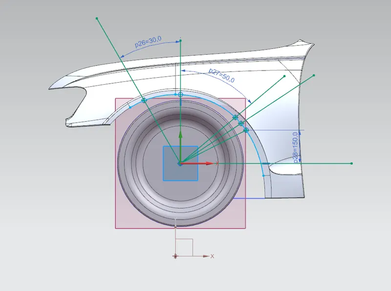
Measure the Clearance L(10mm or above) as per European regulatory requirements.
- At SA
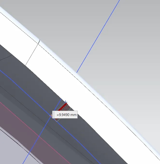
- At SB
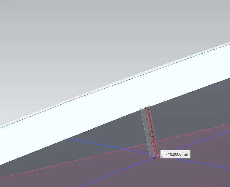
- At SC
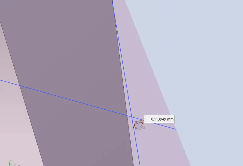
- At SD
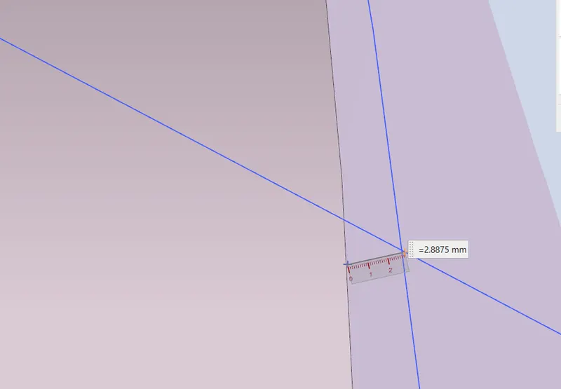
- At SE
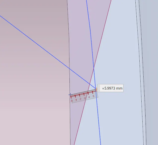
| S.No | Section | Clearance(L) in mm |
| 1 | A | 9.949 |
| 2 | B | 10 |
| 3 | C | 0.113949 |
| 4 | D | 2.8875 |
| 5 | E | 5.9973 |
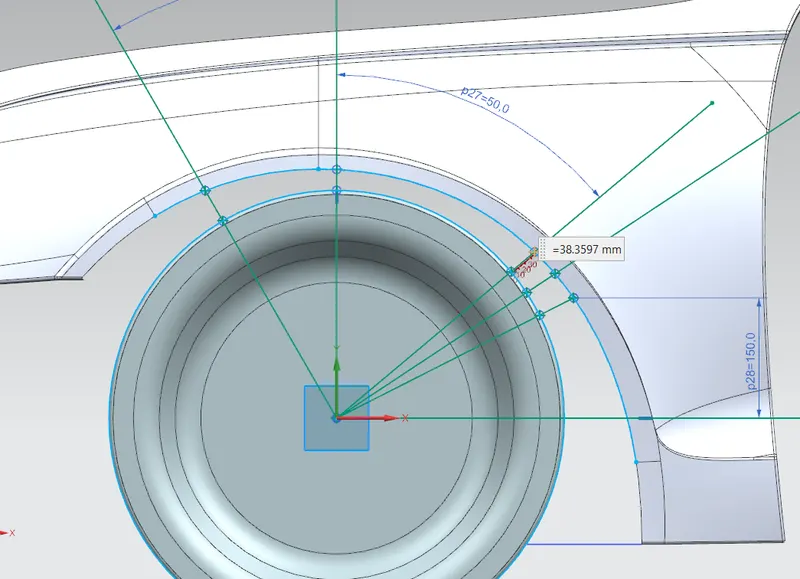
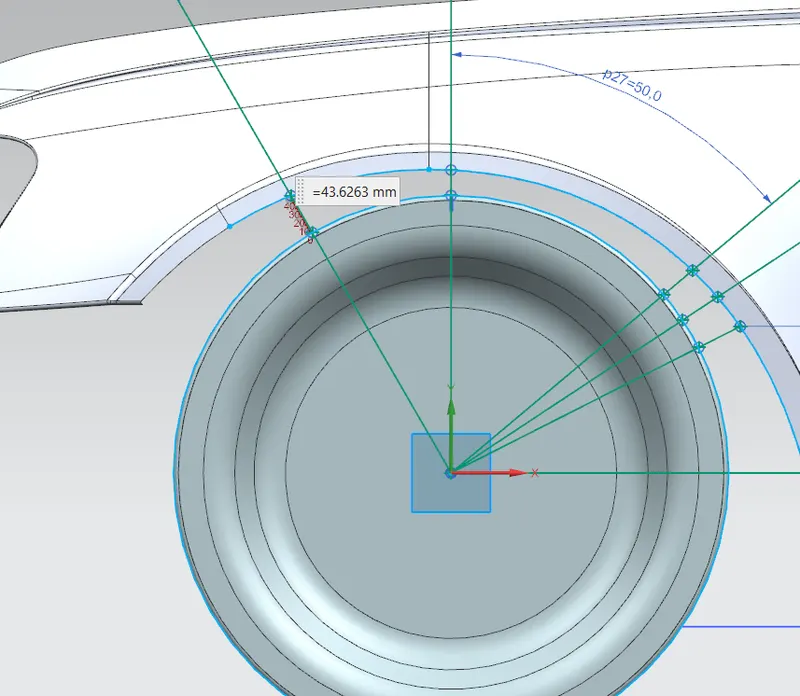
Value of 'a' which should be more than 5mm from the central vertical axis of the wheel.
- At 50 deg intersection line
- At 30 deg intersection line
-
S.No Section Clearance(a) in mm 1 at 30 deg 43.6263 2 at 50 deg 38.3597
Results:
From the above analysis, we can see that the minimum clearance (a) is achieved and clearance(L) is not achieved so we can recommend the styling team to rework on the surface in order to satisfy the European regulation requirement.