Fender Design Challenge
Aim: To prepare a report by explaining Fender Design and its different mounts, manufacturing process, and its design parameters.
Theory: -
1. Fender:
> A metal or plastic enclosure over the wheels of an automobile or other vehicle to protect against splashing mud, etc.
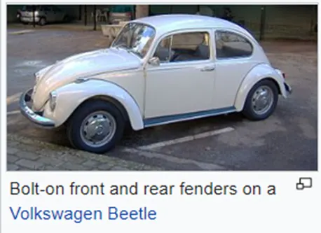
>Fender is the American English term for the part of an automobile, motorcycle, or other vehicle body that frames a wheel well (the fender underside). Its primary purpose is to prevent sand, mud, rocks, liquids, and other roads spray from being thrown into the air by the rotating tire.
2. Types Of Fenders: -
> Full Bumper Type:

> Half Bumper Type:

Advantages of Using Half Bumper Type Fender: -
> Less Material Usage
> Less Overall Costing
> Reduction of weight and overall length
> Improvement in Automobile performance.
3. Areas of Mounting in the Fender: -
>Sill
>Bumper
>A-Pillar
>Drip Area
>Baffle Area
>Cowl
4. Design Considerations in Fender Designing and development of mountings: -
A. Spring Back Effect: -
> It is the phenomenon in which the bent surface tends to recover its original position which is not desirable in structures like U- bent, C- bent, L – bents, etc.
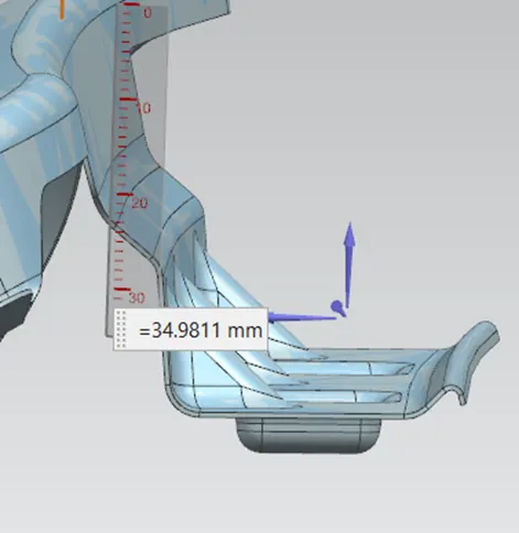
> It takes place majorly in the drip area of the Fender, hence the length of the drip area flange is restricted to 40-60mm.
>Also to avoid such phenomenon to occur, darts are used.
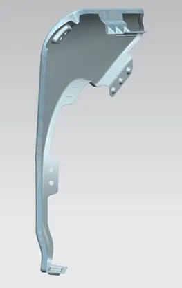
>Below is an image of the fender designed for the project depicting its measurements within the given safe range.
B. Cowl Area Measurement: -
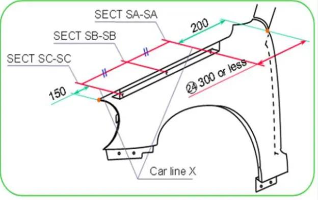
> Cowl is the area of the fender which is attached to the ORVM and the main body windshield vipers, thus appropriate safe length is to be provided to avoid any interference between the component, like in our case 200 mm is the set distance.
C. Baffle Mounting:-
> Baffle is the additional plastic parts added within the fender assembly, to improve the NVH in the cabin.
> Below is an image of the Maruti Brezza, depicting its baffle.

- Design of the Fender: -
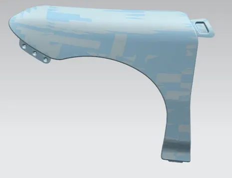
> Master Section:-
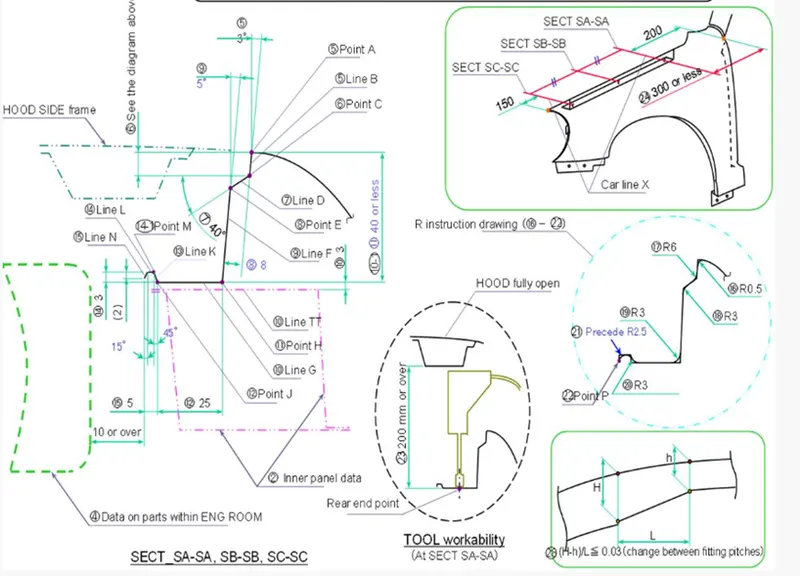
> We start by first using the command ‘curve on the surface’ in the Curve section to cut the sheet of the fender according to the master section and the desired lengths of the different mounting sections.
>Now, we make a desirable offset from the top section of the fender to provide an optimum surface for the fender outer surface, i.e 5 mm in our design.
> Then after making the boundaries on the Fender, we use the trim command in the surface section, to remove the undesirable sheet metal.
> Now we proceed to make the Drip area first, in which we first need to provide the required 200 mm distance in the cowl section from the A-pillar side, hence we use the command ‘datum’ and then choose ‘on the curve’, then we select the base point from the A-pillar mounting and choose the curve, then we offset it to 200 mm.
> Then we make use of law extension and make flanges of the drip area as per the master section.
> Then we again create a datum plane to make the design of the mounting and use emboss feature.
> Later on we provide optimum face blends and edge blends.
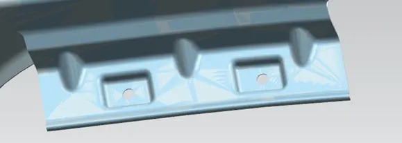
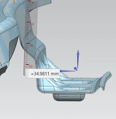
> Now we come to the A-pillar mounting, in which we first make a new surface to draw the sketch.
> Then we project the sketch on the desired surface and use the emboss feature and followed by a trim surface to make the cut-outs for the mounting bolts.
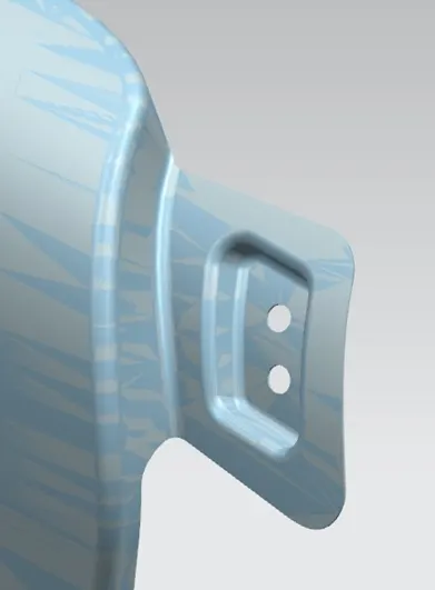
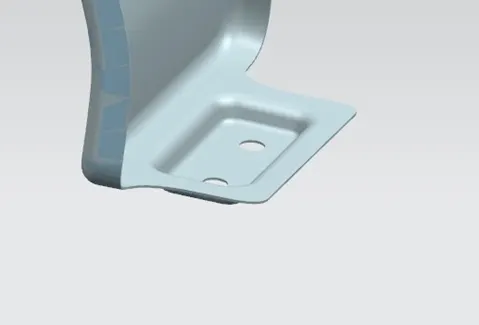
> Then we Come to sill mounting, in which we first use the ‘Extend Sheet’ command in the Surface section, and extend the sheet to optimum distance.
> Then we make a new surface to draw the sketch, and we project the sketch on the desired surface and use the emboss feature and followed by a trim surface to make the cut-outs for the mounting bolts.
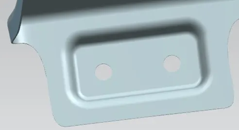
> Following which we now design the baffle mountings in which we have already made cut-outs in two separate places for the mountings.
> In these two sections we make a new surface to draw the sketch, and we project the sketch on the desired surface followed by a trim surface to make the cut-outs for the bush pins of the baffle mounting.
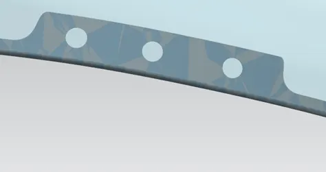
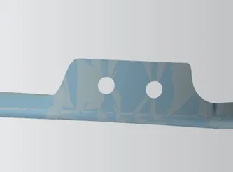
> Now at the end, we reach the bumper mounting, in which we first use the ‘Extend Sheet’ command in the Surface section, and extend the sheet to the optimum distance and desired angle.
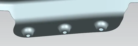
> Then we make a new surface to draw the sketch, and we project the sketch on the desired surface and use the emboss feature and followed by a trim surface to make the cut-outs for the mounting bolts.

6. Manufacturing Processes:-
> Punch Press:-

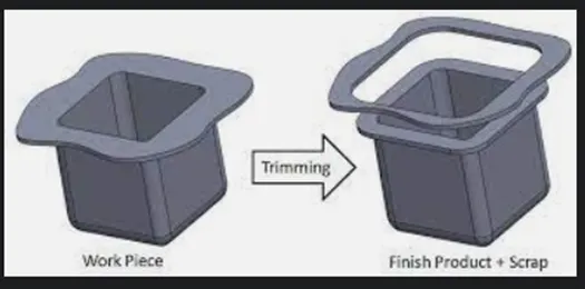
>Trimming:-
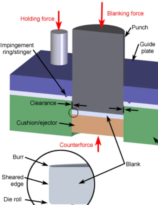
> Blanking:-
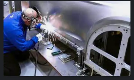
> MIG Welding:
Conclusion:-
The fender is an integral part of the automobile, hence all the design considerations need to be followed and the designer should focus on both aesthetic and manufacturing points of view as well, as designing the fender.