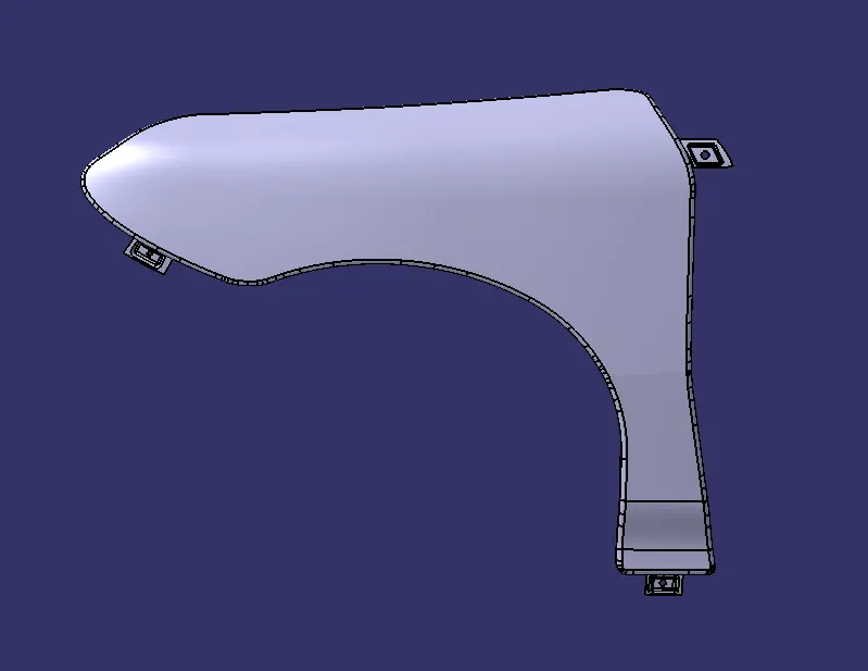
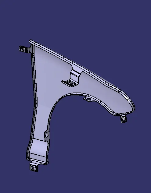
Fender Design Challenge
Aim:
To create a Fender from the given Class A surface with Flanges and Drip area which comes in a fender.
Explanation:
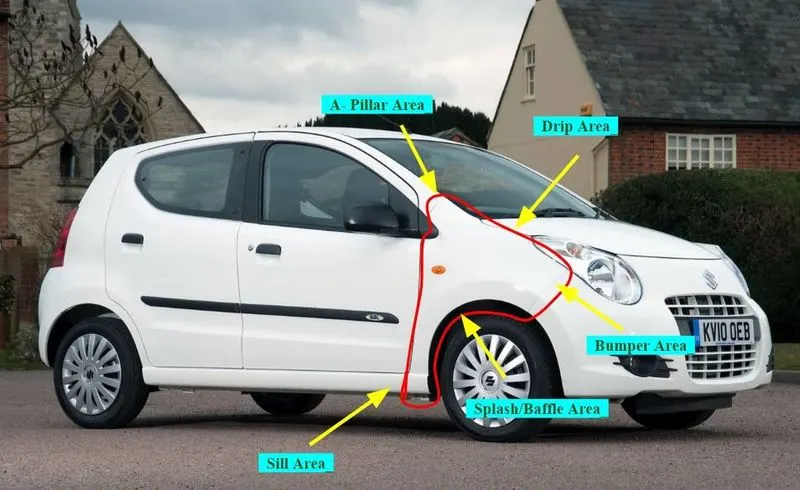
A fender is the part of a car that protects and frames its wheels and keeps mud from splashing it. Most modern vehicles have fenders on their front wheels. When you get into a minor car accident, you can call it a "fender bender," and it's possible that your fenders did get slightly dented.The fender has flanges which is used to fix them to the A pillar of the car , drip area to the engine bay , sill area to the bottom and flanges on bumper area to attach it to the bumper, it also as area for baffles or splash along the wheel arc.
Creation of Fender:
- First all the surface from the given model are joined to form a single surface and then the points where the flanges come are first drawn on the surface of the Class A and then splitted to get the required shape.
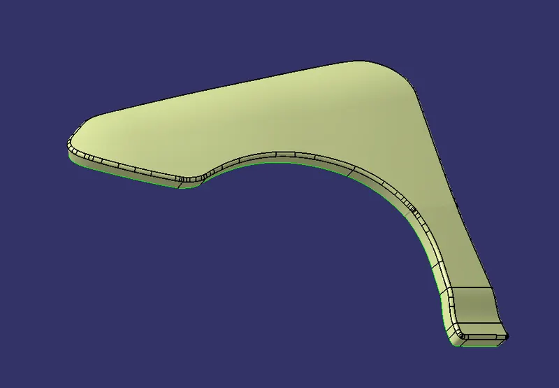
- Some irregularities are then removed and corrected to form a smooth surface.
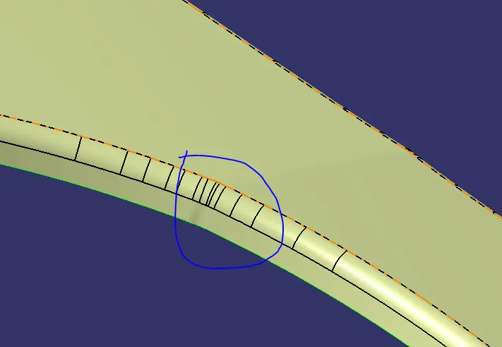
- Then the boundary of the surface is offseted using parallel curve command and whereverthe flange is required it is then marked on that boundary for later splitting them.
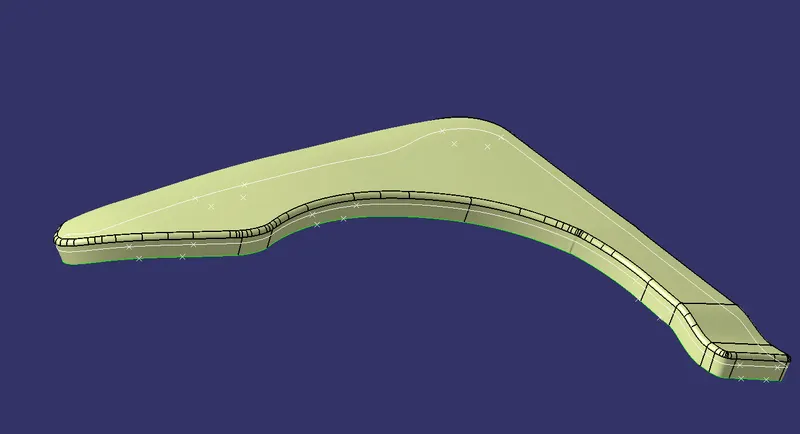
- Then after splitting we get the required surface for the flanges as shown below,
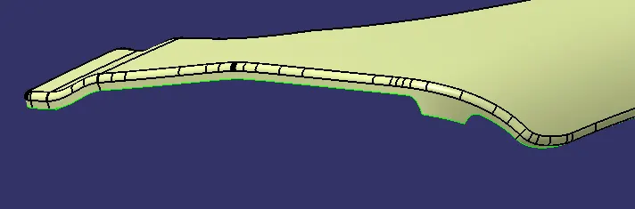
The above shown is the place where the flange is created to attach it to the A pillar.
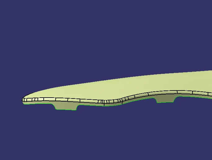
The above shown is the place where the flange is created to attach it to the Bumper .
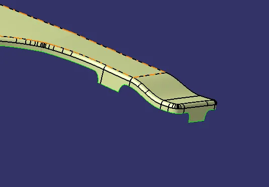
The above shown is the place where the flange is created to attach it to the sill area.
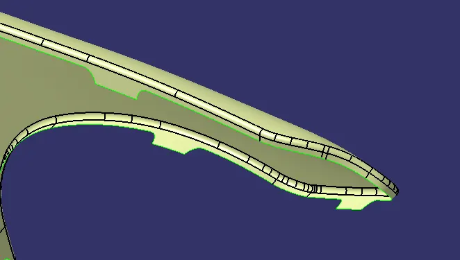
The above shown is the place where the flange is created to attach it to the engine bay.
- The flanges for the drip area is created with the taking note of calculations to correctly sit inside the engine bay at the same time should have a distance 10mm or over and the length of flange position should be 40 or more.
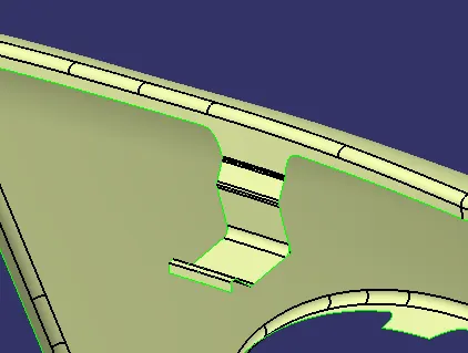
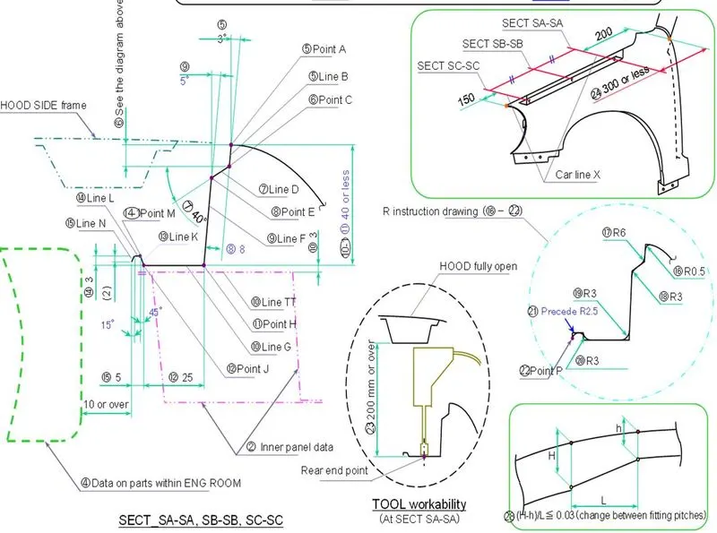
The above shown image and parameters are the measurements and claculations to take note of while designing this fender.
- And after creating a surface for the flanges with all the parameters taken into consideration now we create a emboss on each flange for the nut and bolt to be placed and fitted.
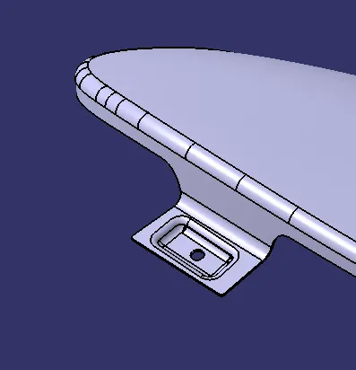 - Bumper area flange with emboss.
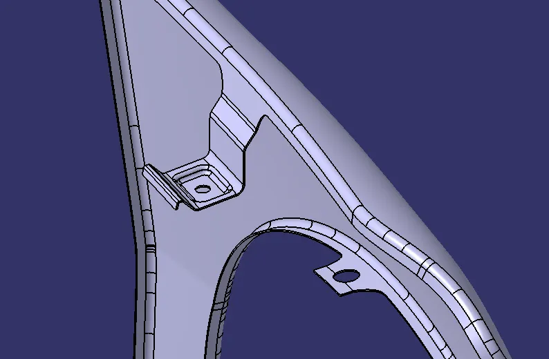 - Emboss cretaed on the drip area.
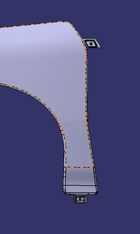 - Sill and A pillar area with emboss created over it.
- Now that we have created the required flanges we then thicken it to 0.75mm as it is the minimum thikness and we finish the model. Now our model is ready to be tested in real world and after testing it is ready for prodcution.