Fender Design Challenge
AIM:
To design the car fender and the necessary mounts by following the Master section.
INTRODUCTION:
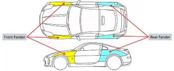
Fender is the part of an automobile, motorcycle or other vehicle body that frames a wheel well (the fender underside). Its primary purpose is to prevent sand, mud, rocks, liquids, and other road spray from being thrown into the air by the rotating tire. Fenders are typically rigid and can be damaged by contact with the road surface.
Sticky materials, such as mud, may adhere to the smooth outer tire surface, while smooth loose objects, such as stones, can become temporarily embedded in the tread grooves as the tire rolls over the ground. These materials can be ejected from the surface of the tire at high velocity as the tire imparts kinetic energy to the attached objects. For a vehicle moving forward, the top of the tire is rotating upward and forward, and can throw objects into the air at other vehicles or pedestrians in front of the vehicle.
PROCEDURE:
Bumper mounting area
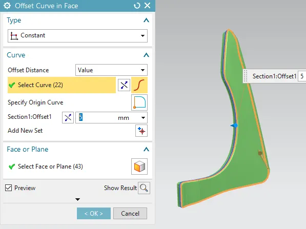
- First open the fender part and offset the surve in fender side face for 5 mm using offset curve in face command.
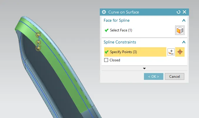
- Next create bumper mounting edges by using curve on surface and select the face, spline points as well with infer G1 at start and end point for one side.
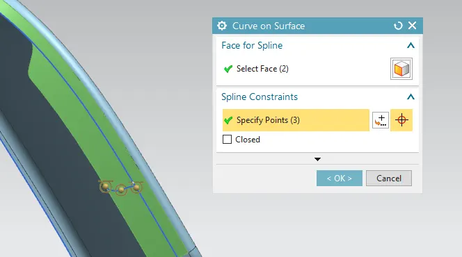
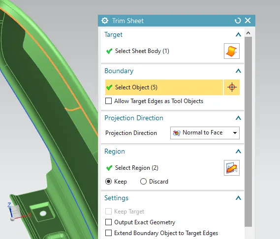
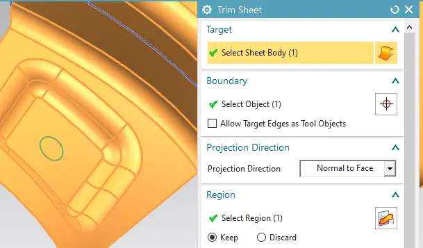
- Then trim the other edges except the mount and also untick the extend boundary option using trim sheet command.
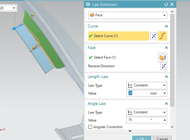
- Use law extension command to draw the mount for 20 mm at 75 degree angle.
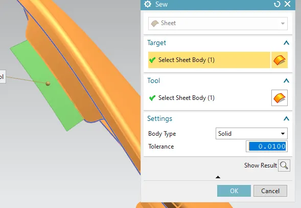
- Sew the extended mount face and the body together.
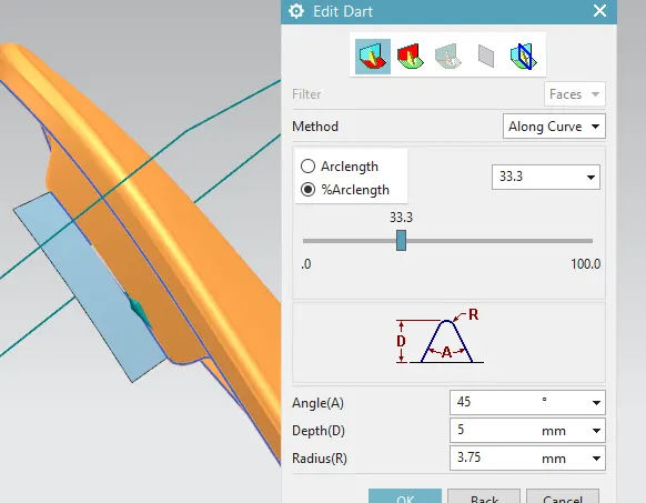
- Now create a dart for the bumper mount for 5 mm depth, radius 3.75 mm and an angle of 45 degree.
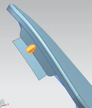
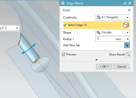
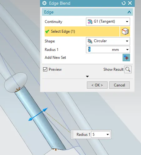
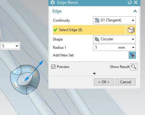
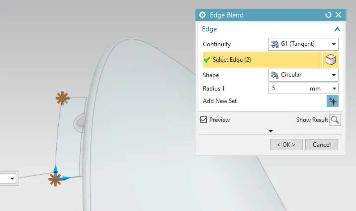
- Apply the edge blend for the given master section of 5 mm.
Drip mounting area
- Create datum plane to create mount edges at two positions for 40 mm and 150 mm.
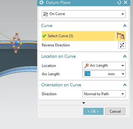
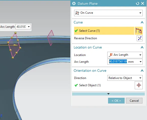
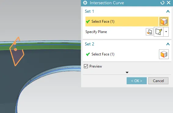
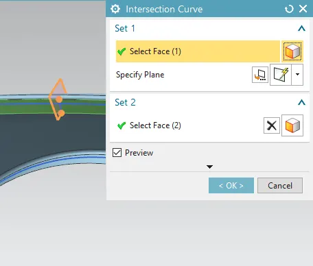
- Create an intersection curve between the datum plane and mount faces.
- Next create dip mounting edges by using curve on surface and select the face, spline points as well with infer G1 at start and end point for both side.
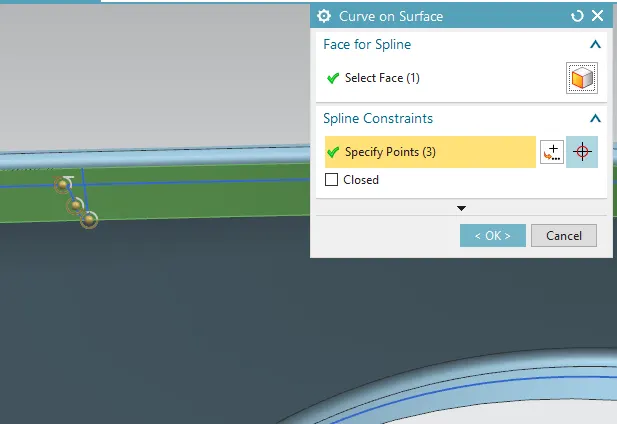
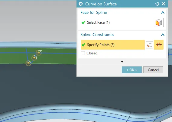
- Then trim the other edges except the mount and also untick the extend boundary option using trim sheet command.
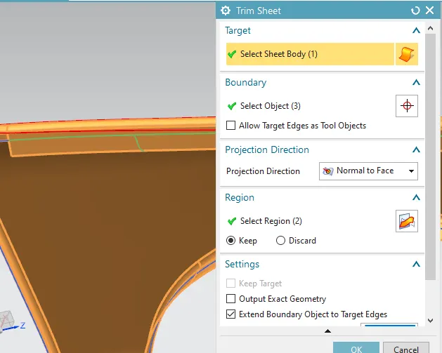
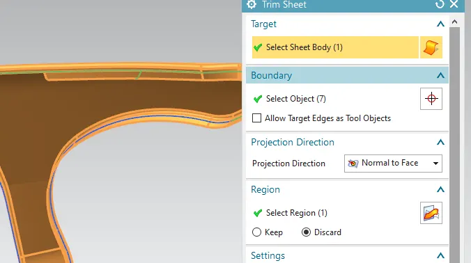
- Use law extension command to draw the mount for 8 mm at 40 degree angle.
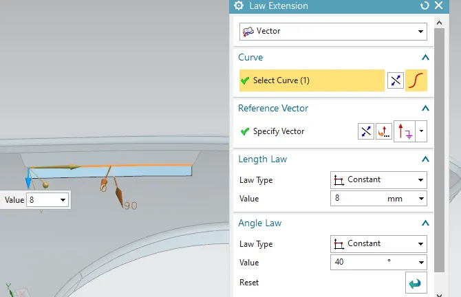
- Then continously add the dip mounting faces by using law extensions for the given master section.
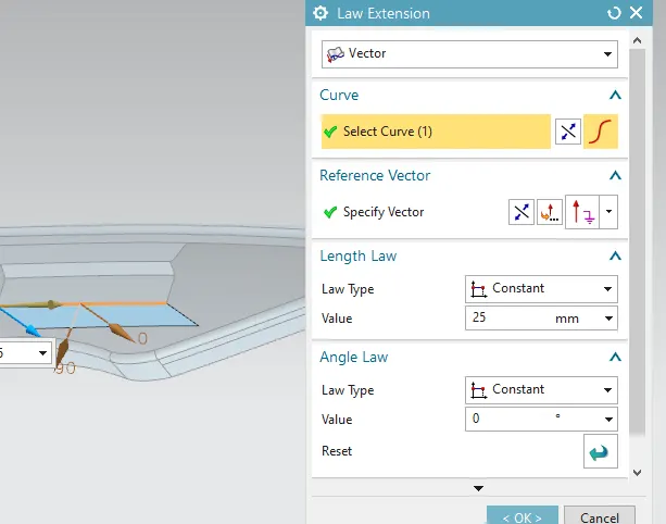
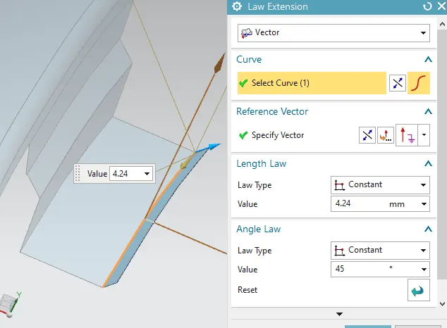
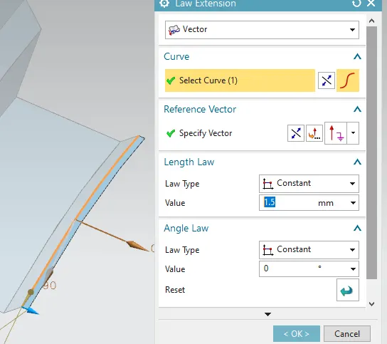
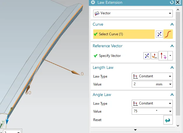
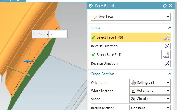
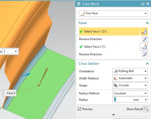
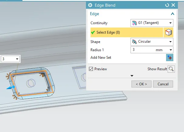
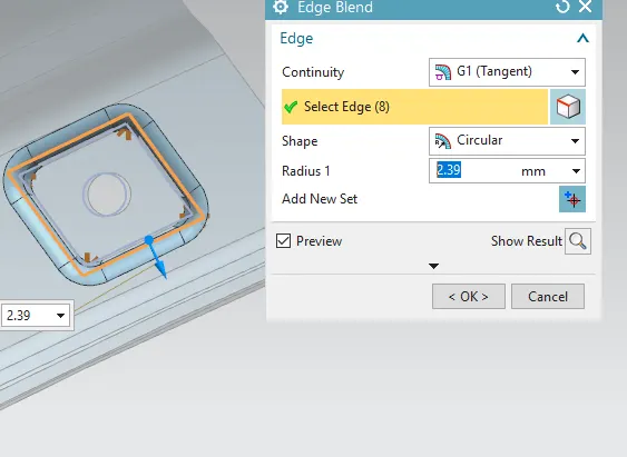
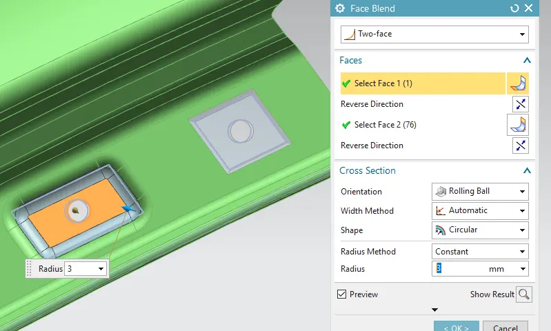
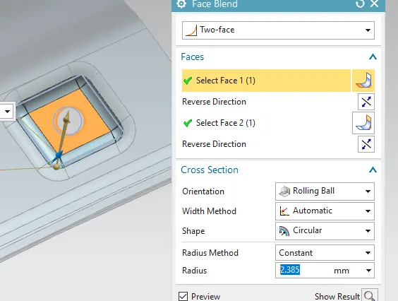
- Apply the edge blend and face blend for the given master section of 6 mm.
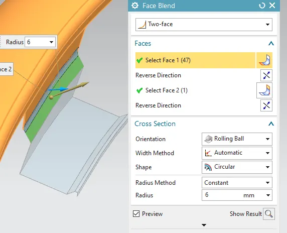
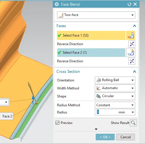
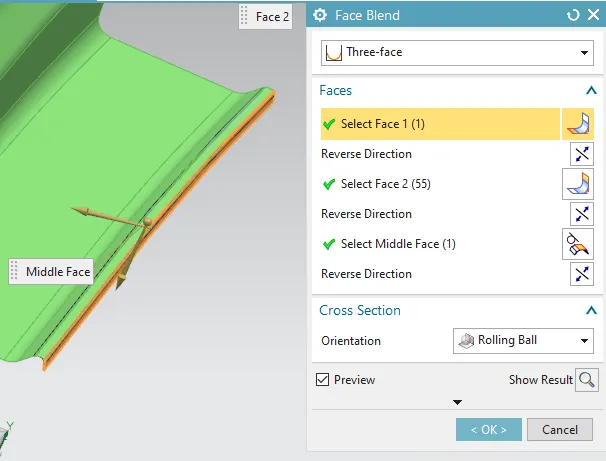
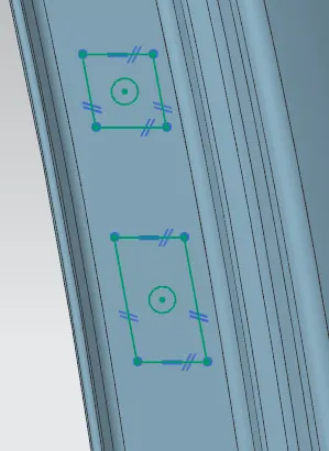
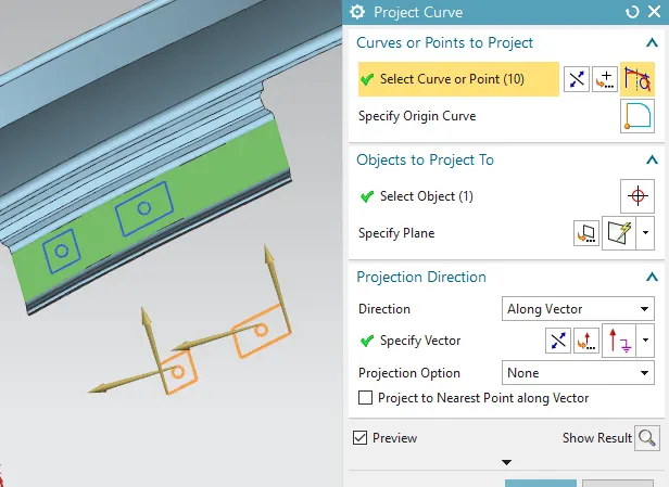
- Sketch the mount attachment and hole in the drawn face and project the curve to the face.
- Next project the curve in face and create a datum plane for the embosement.
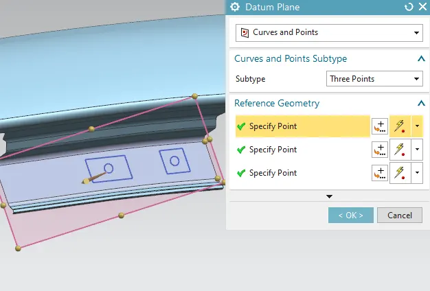
- Now emboss the inner section of mount for 3.5 mm at 15 degree angle.
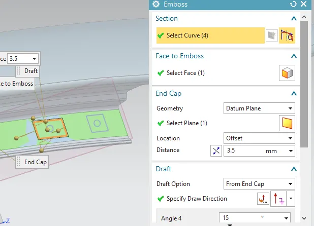
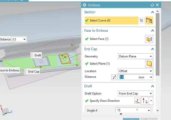
- And trim the sheet mount holes for the dip mounting area.
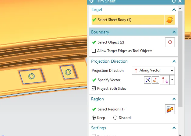
- Apply the edge blend and face blend for the base sheet of master section.
Baffle mounting area
- Next create baffle mounting edges by using curve on surface and select the face, spline points as well with infer G1 at start and end point for both side in 3 places.
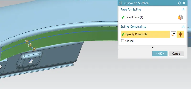
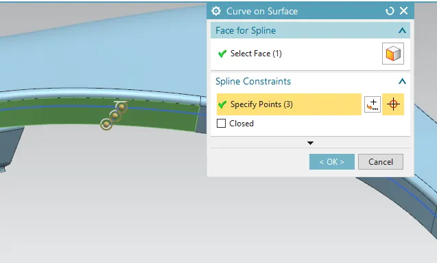
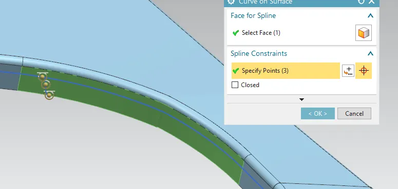
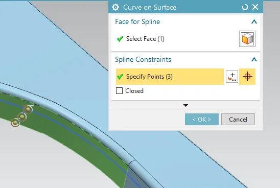
- For bottom baffle mount, offset the curve in face for 8 mm and add the spline points to trim the mount edges.
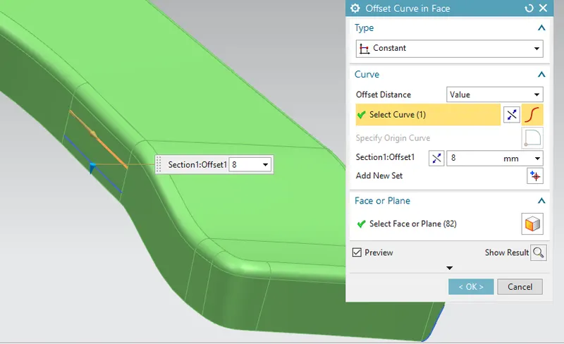
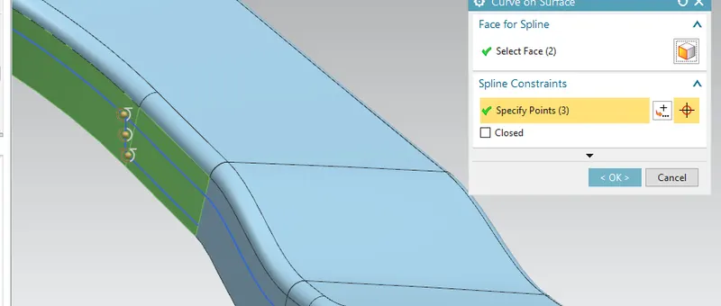
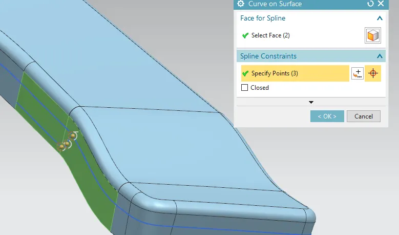
- Then trim the other edges except the mount and also untick the extend boundary option using trim sheet command.
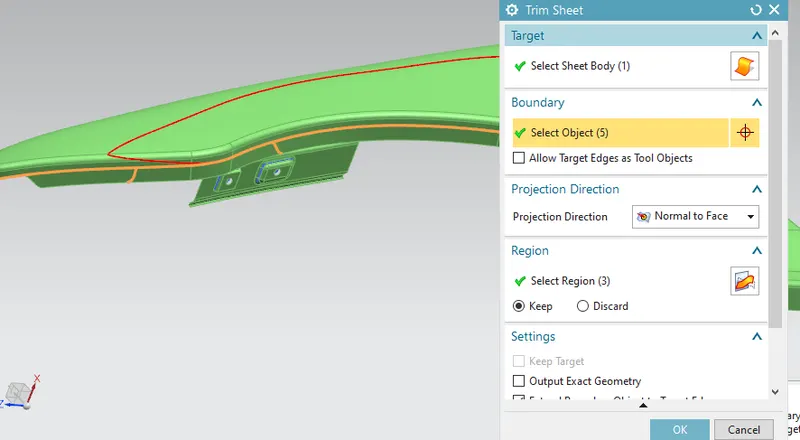
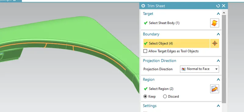
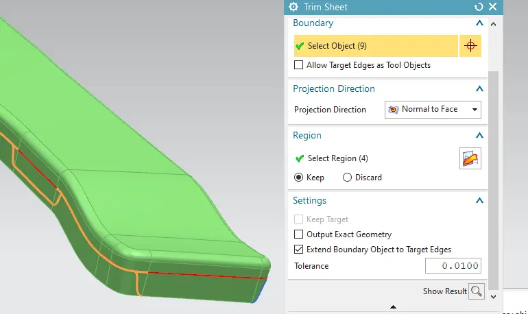
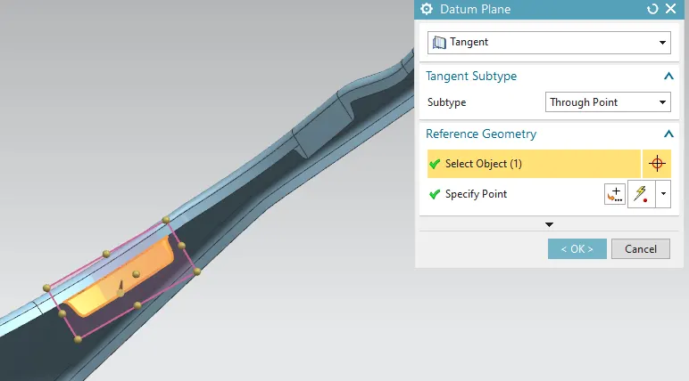
- create a datum plane for the mount holes by selecting the mount face.
- Sketch the hole in the drawn face and project the curve to the face.
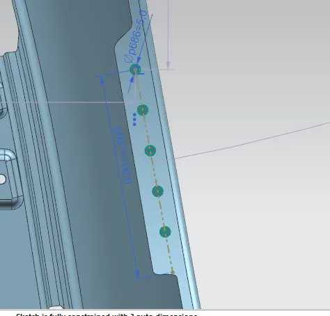
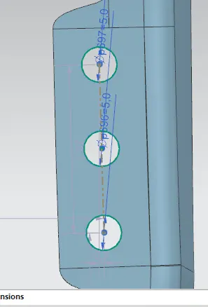
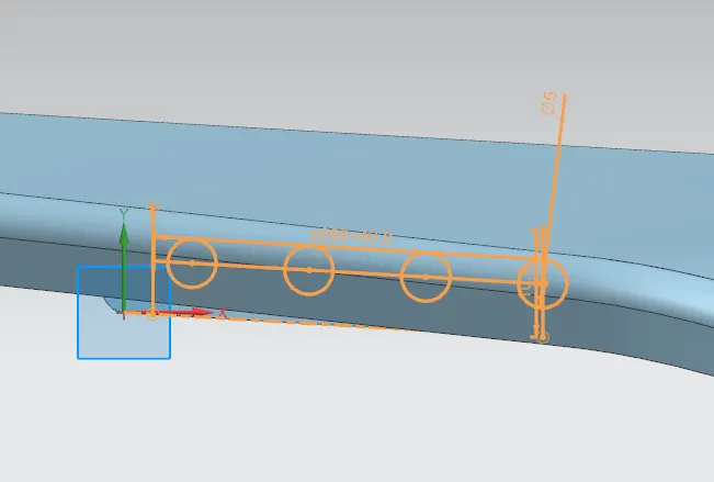
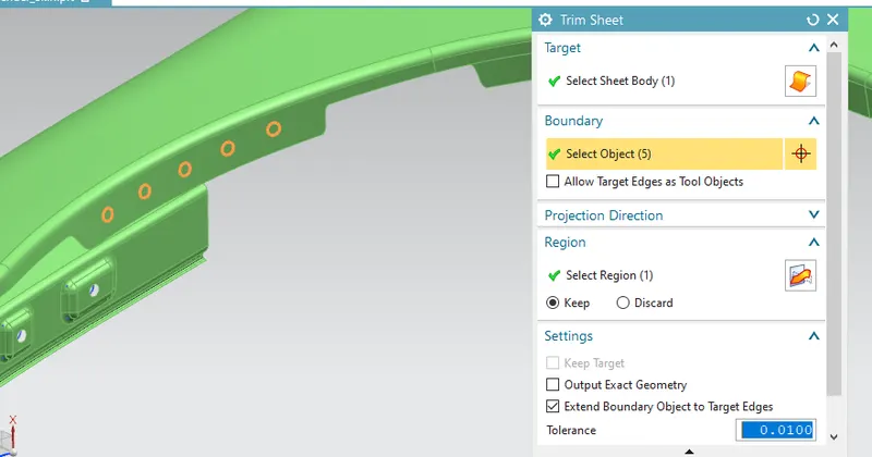
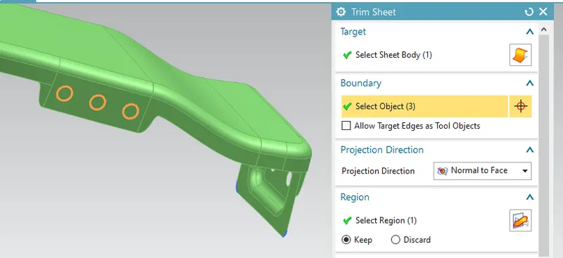
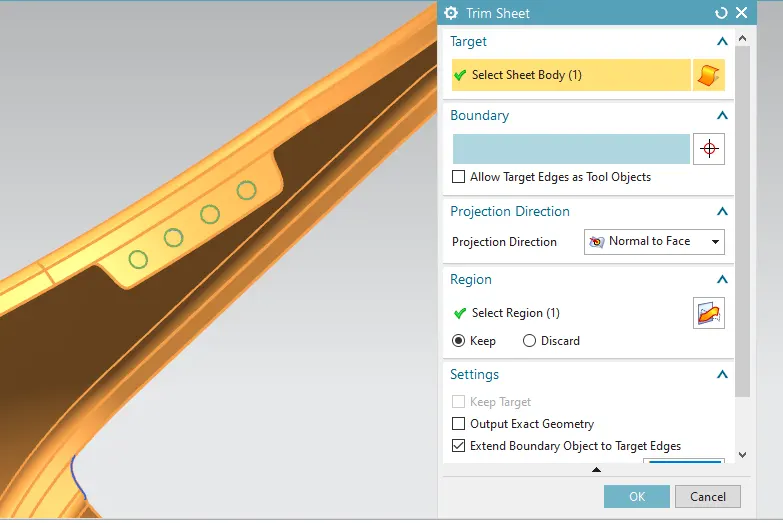
- Next project the curve in face and trim the sheet mount holes for the baffle mounting area.
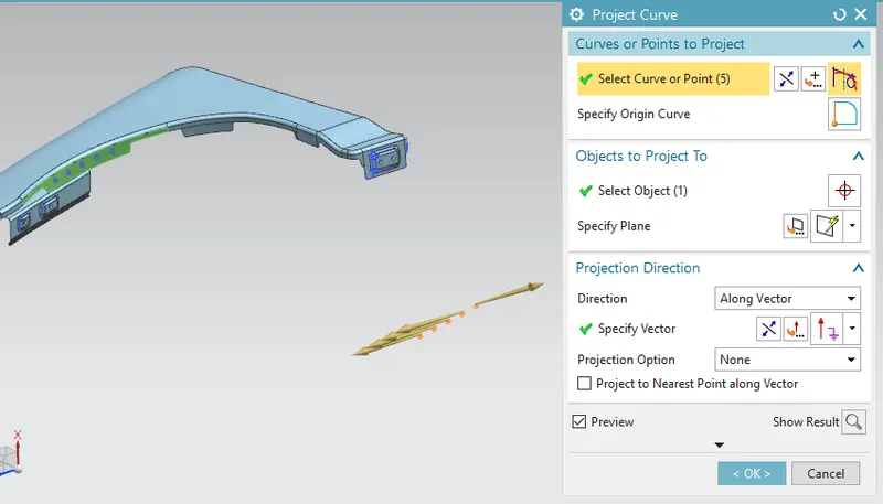
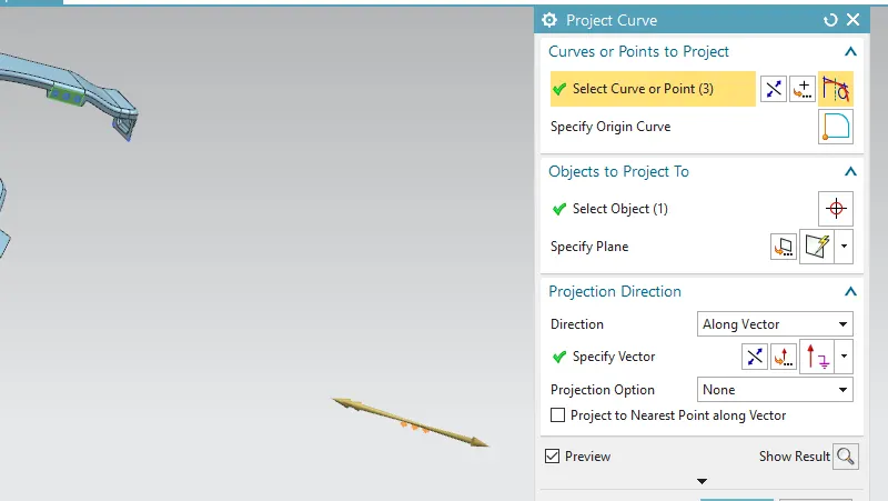
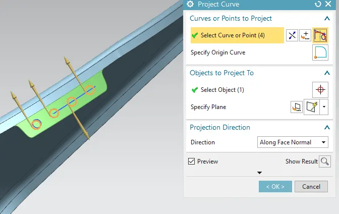
- Now trim the sheet mount holes for the baffle mounting area.
sill mounting area
- Next create sill mounting edges by using curve on surface and select the face, spline points as well with infer G1 at start and end point for both side.
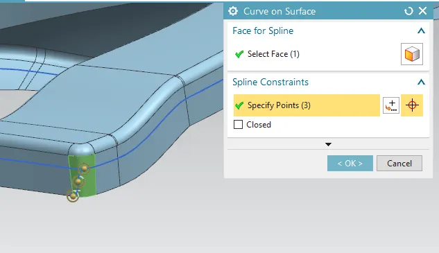
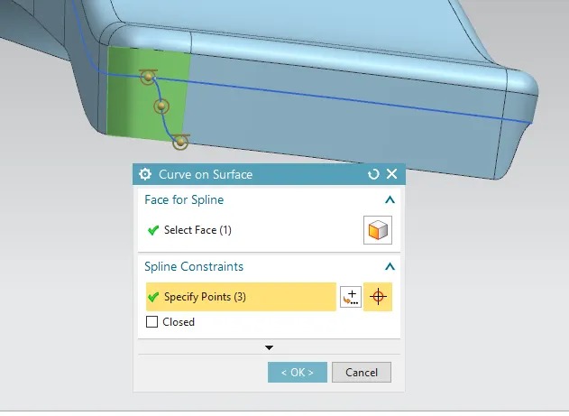
- Then trim the other edges except the mount and also untick the extend boundary option using trim sheet command.
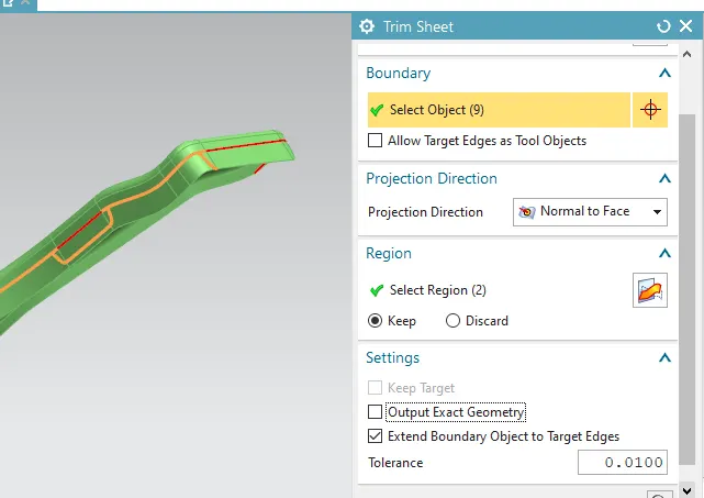
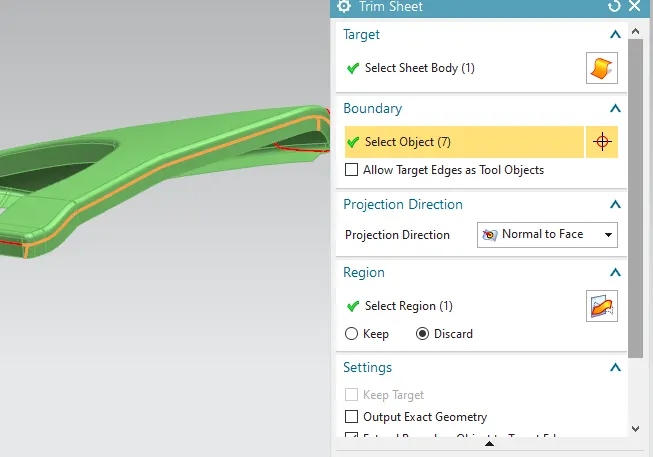
- Use extend sheet command to draw the mount for 15 mm.
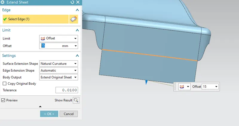
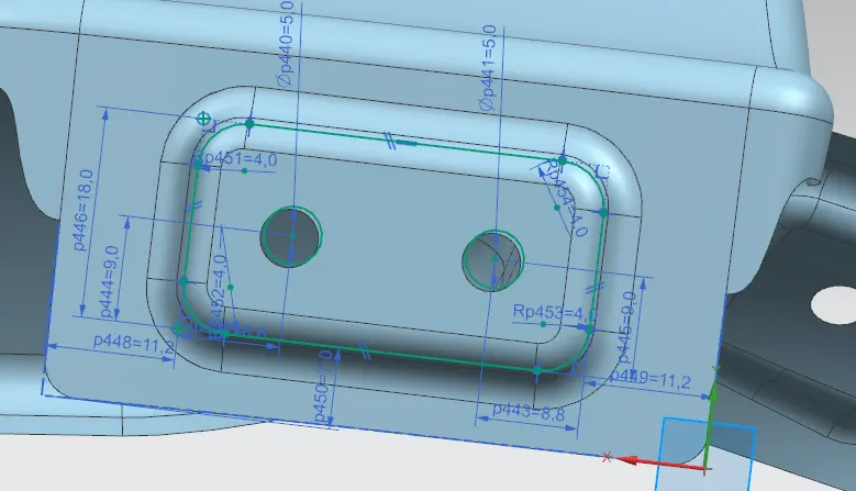
- Sketch the mount attachment and hole in the drawn face and project the curve to the face.
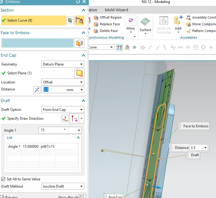
- Now emboss the inner section of mount for 3.5 mm at 15 degree angle.
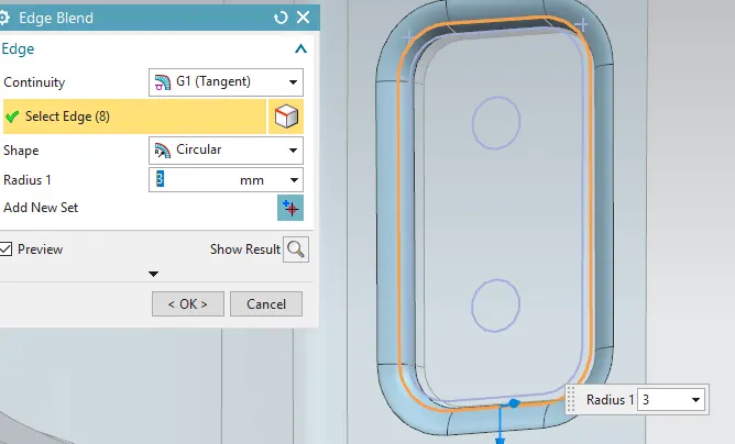
- Apply the edge blend and face blend for the given master section of 3 mm.
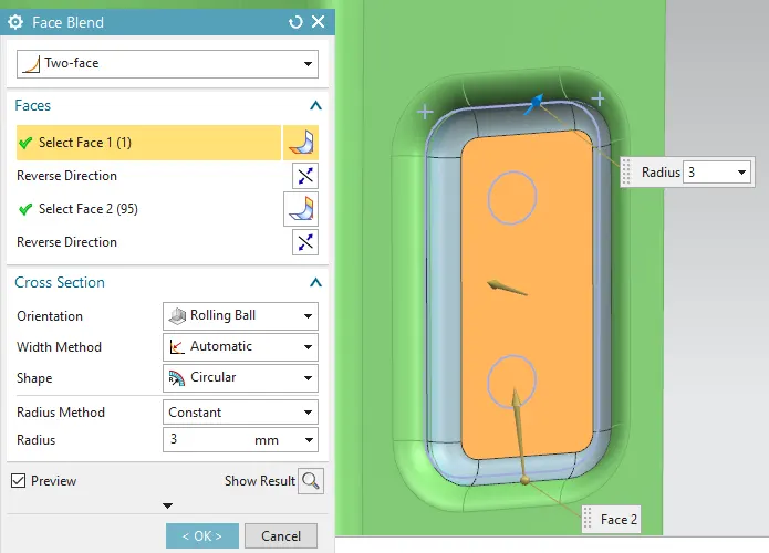
- Next project the curve in face and trim the sheet mount holes for the bumper mounting area.
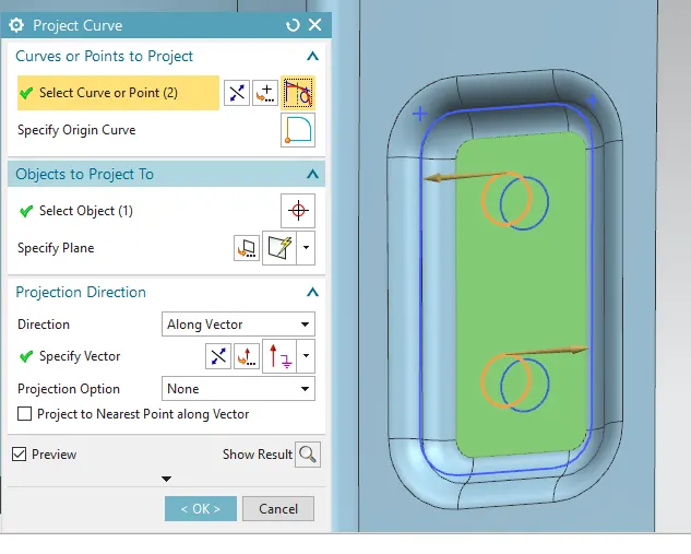
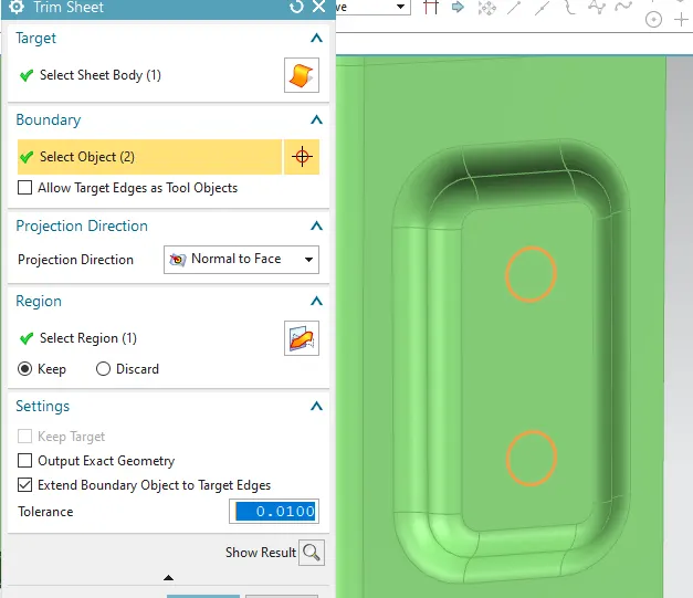
'A' mounting area
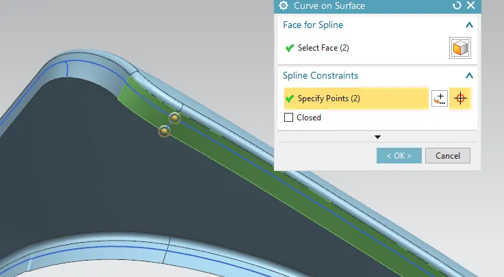
- Next create bumper mounting edges by using curve on surface and select the face, spline points as well with infer G1 at start and end point for one side.
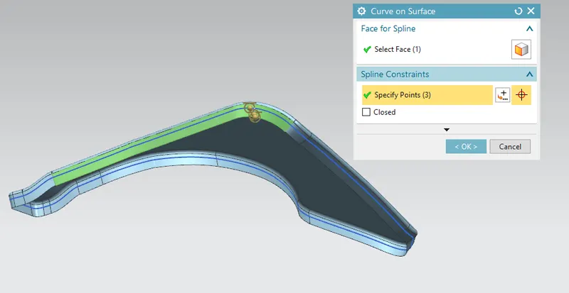
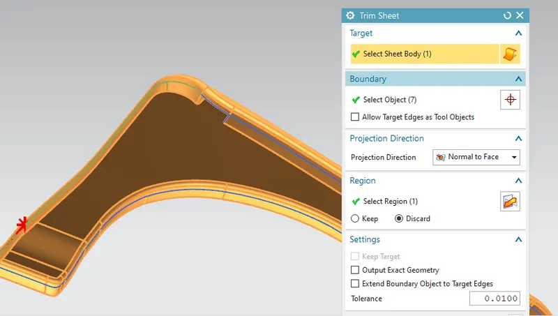
- Then trim the other edges except the mount and also untick the extend boundary option using trim sheet command.
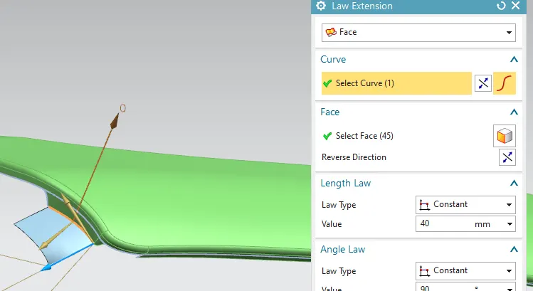
- Use law extension command to draw the mount for 40 mm at 90 degree angle.
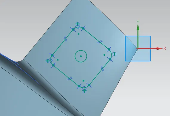
- Sketch the mount attachment and hole in the drawn face and project the curve to the face.
- Now emboss the inner section of mount for 3.5 mm at 15 degree angle.
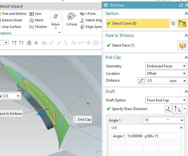
- Apply the edge blend and face blend for the given master section.
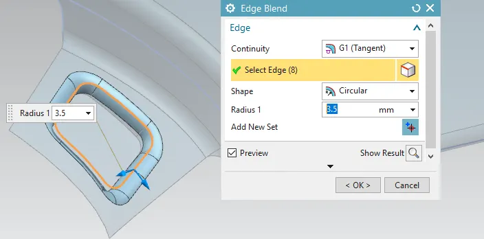
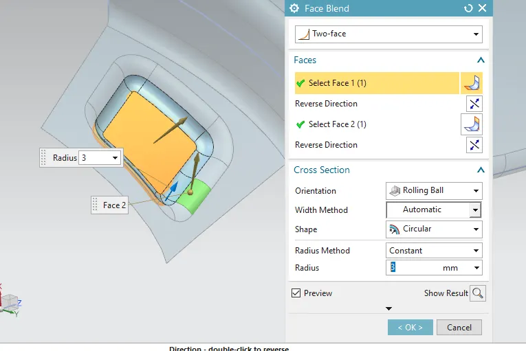
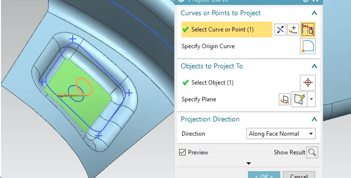
- Next project the curve in face and trim the sheet mount holes for the bumper mounting area.
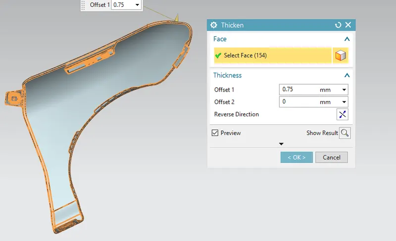
- Thicken the surface for 0.75 mm.
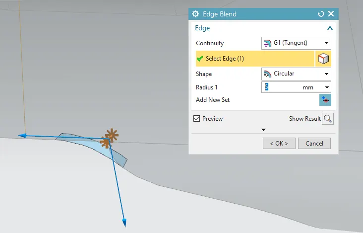
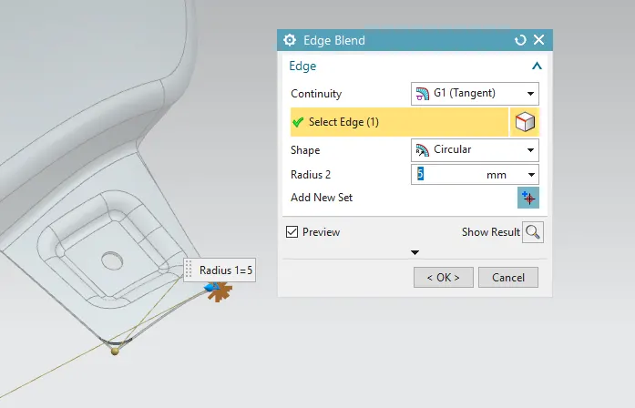
- Create edge blend for sharper edges for 5 mm.

CONCLUSION:
The following images are the designed assembly of the complete hood or bonet of a car.
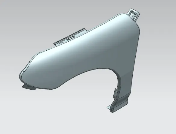
3D view
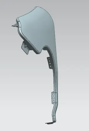
Front view
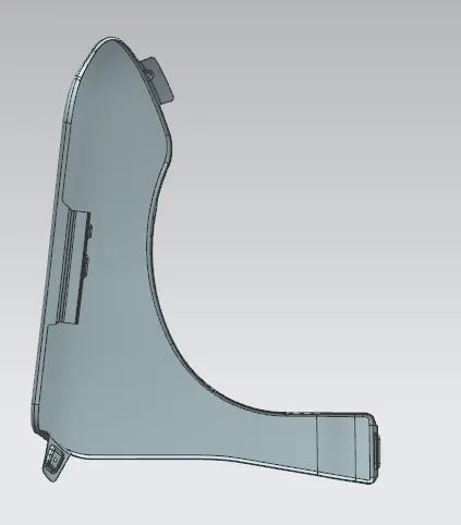
Bottom view
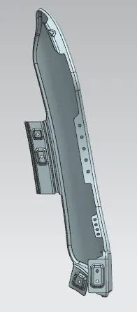
Side view