Fender Design Challenge
Title of the project: Fender Design Challenge
Objective: To design various mounting points like Drip Area mounting, Sill Mounting, Bumper mounting, A-Pillar mounting and Baffle mounting on the front fender with design consideration.
Introduction: A fender is the curved portion of the car’s body that sits over and houses the wheel. It is the side covering unit of the engine compartment. Its function is to keep mud, rocks, and other road debris from being thrown around by the tyres. It also enhances the overall look of the car. In other words, fender is the housing for the wheels that keeps road debris contained. If there was nothing covering the wheels, all kinds of debris would be kicked up by the rotating tyres.
The fender not only protects our car from sustaining damage from road debris but it prevents this debris from being thrown up at other vehicles on the road. This is why the vehicles with large, oversized tyre are often required by law to install fender flares.
Fender is made aerodynamic in shape to reduce the air drag.
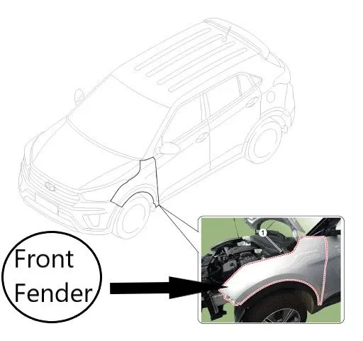
Fig.1: Front Fender
Types of Automobile fender:
- Full Bumper Type
- Half Bumper Type
Full fender use a large blank size resulting in a large amount of scrap metal which results in increased manufacturing cost. On the other hand, if we increase the size of the blank slightly we can manufacture 2 half fender from the same sheet metal blank. This results in the low cost of the material. This is the reason half bumper type fenders are used in automobile these days.
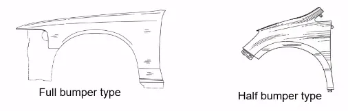
Fig.2: Types of fender
Mounting:
There are 5 mounting points in a fender.
- Body
- A Pillar
- Sill
- Cowl
- Drip
Master section for drip area:
This master section is used to create drip area and rest of the mounting points should be created as per the design requirements.
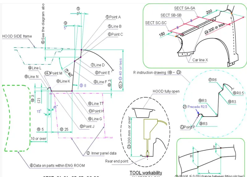
Fig.3(a): Master section for Drip area
Styling data:
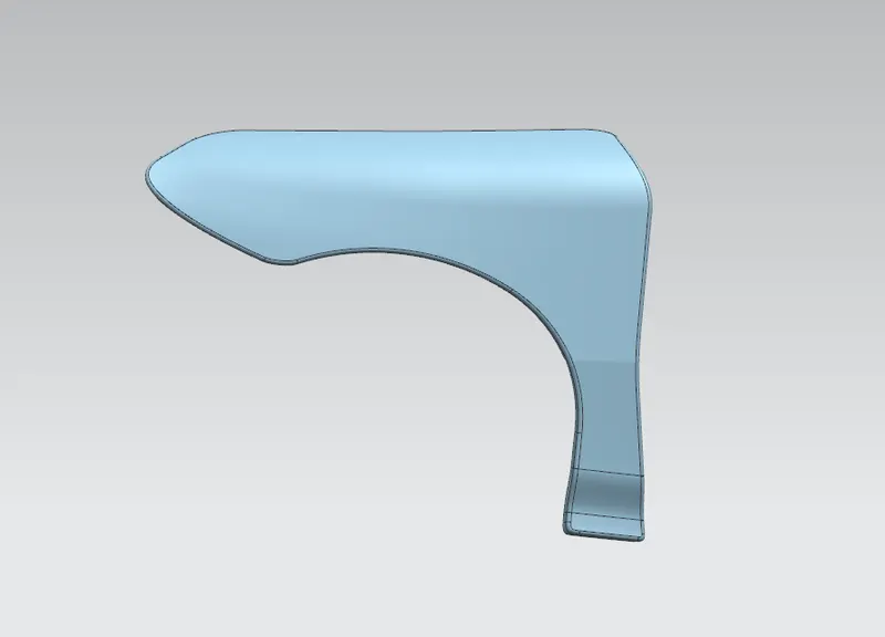
Drip Area:
It is a critical mounting area located inside the engine component. It is mounted to engine compartment by weld nuts.
Design consideration for the Drip Area:
- During designing of the front fender the angle gap between the fender and the hood is 3 degree minimum.
- There should be 150 mm gap from for head light housing from front of the fender and also 300 mm or less clearance from back of the fender for easy installation of component in engine bay.
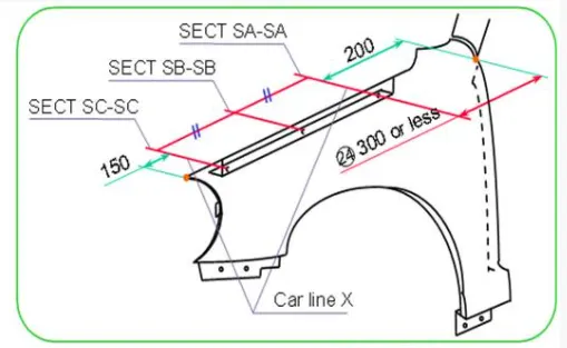
Fig.4: Measurement of drip area
- A minimum of 5 mm flatness is given to all mounting holes except for baffle mounting area.
- Drip area should not reach the engine assembly due to restriction of 40 mm length so there will some L-Shaped Bracket to connect with it.
- The engine component should not be visible from outside. For this we have been given 3 degree of angle and around 9 mm length (not 10 mm or over).
- The other parameters should be taken in consideration as per the given master section.
Drip Area Mounting:
As the drip area was designed as per the design requirements, embosses were given making the mounting area along with the 5 mm flatness on the holes located on the embossed region. The dart was given on the edge of the drip zone giving it more stability and adding strength to the material.
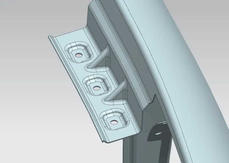
Fig.5: Drip Area Mounting
A-Pillar Mounting:
This mounting region is located near the cowl of the vehicle where the fender is fastened with the bottom edge of the windshield. This region is mounted to the A-Pillar frame of the chassis so that it is rigidly attached to the body of the car.
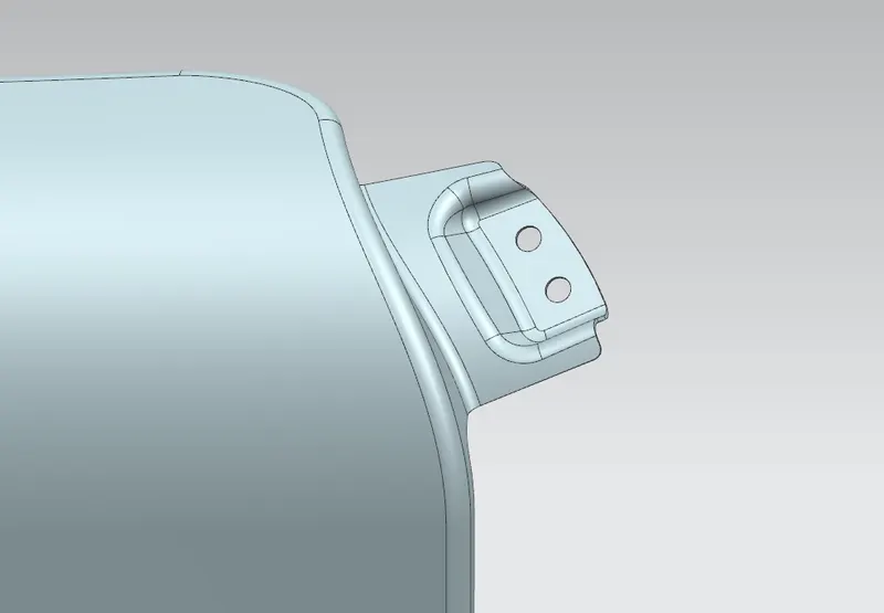
Fig.6: A-Pillar Mounting
Sill Mounting Area:
This is the area at which the bottom of the fender gets connected to the floor near the bottom edge of the door. The embossed sill mounting of the fender is attached with the fasteners.
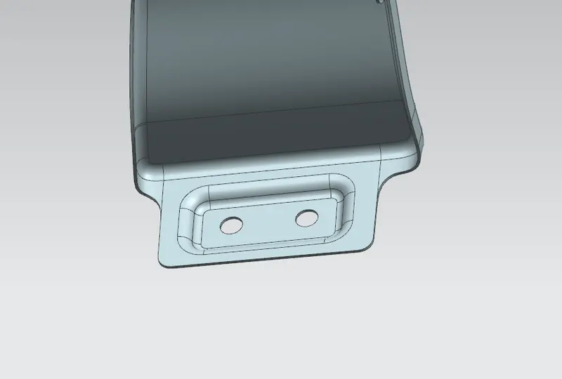
Fig.7: Sill Mounting Area
Bumper Mounting Area:
The bumper mounting area is located beneath the bumper. The fender gets attached before the installation of the bumper. After fixing the fender with fasteners the bumper will cover the bumper mounting.
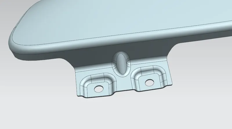
Fig.8: Bumper Mounting Area
Baffle Mounting Area:
In this region, the baffle gets attached with the help of clips which hold the baffle with the fender along with the wheel arch.
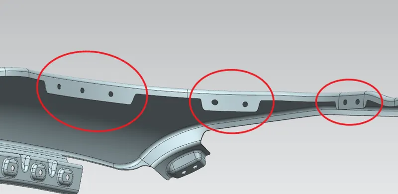
Fig.9: Baffle Mounting Area
Different views of Fender:
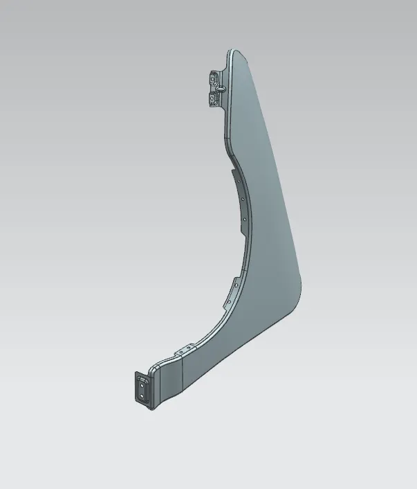
Fig.10: Isometric View
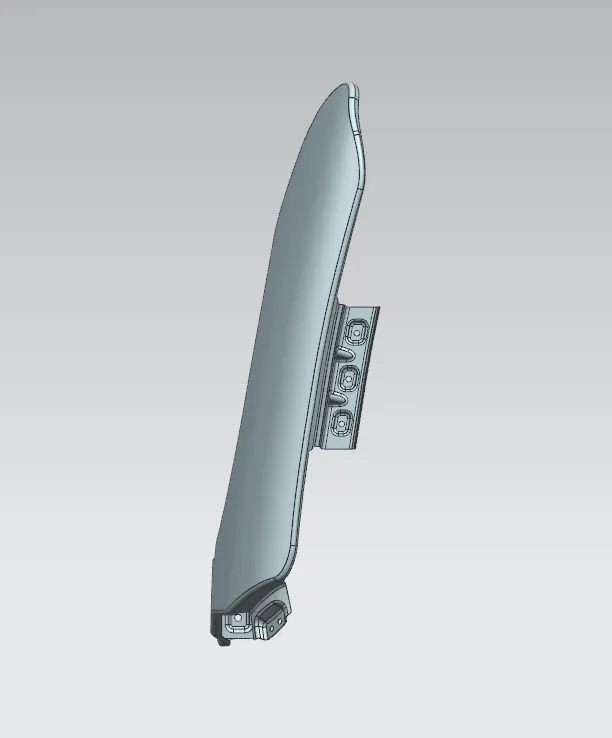
Fig.11: Back View
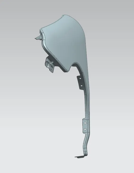
Fig.12: Top View
Manufacturing Process for a Car Fender:
The manufacturing process of a fender includes various steps which are as follows;
- Firstly, unfolding and shearing are carried out on a plate, wherein a proper cold roll specification is selected at first, a cold roll is unfolded, and then the unfolded cold roll is sheared to an iron plate of the corresponding size according to production material specification.
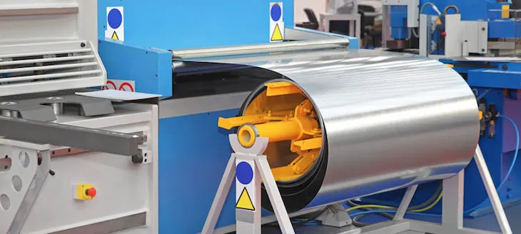
Fig.13: Shearing of sheet metal
- Secondly, oil pressing and punching are carried out, wherein the iron plate is extended at first, then side shearing and punching are conducted on the iron plate then folding and shaping are done on the iron plate and finally reshaping is done on the same plate.
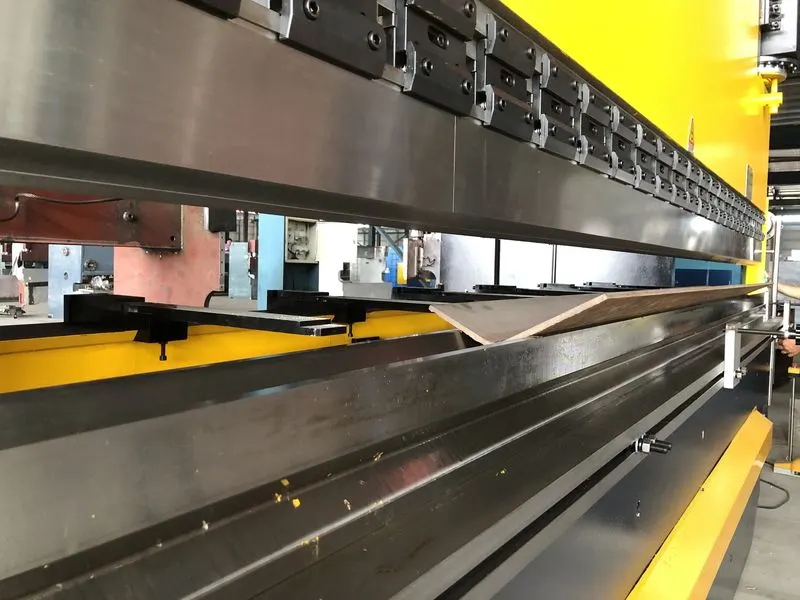
Fig.14: Oil Pressing
- Thirdly, small first parts of the fender are machined, wherein first of all, the iron plate is punched to a needed outer counter blank, then the iron plate completing the outer counter blank is further shaped, and the iron plate is punched at last.
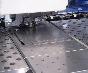
Fig.15: Sheet metal Punching
- Fourthly, installation and welding of a metal plate are conducted.
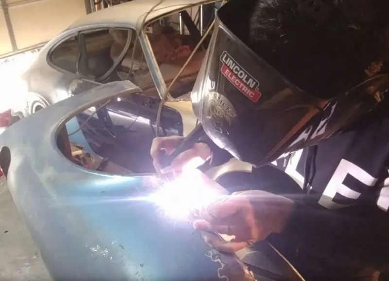
Fig.16: Tig Welding
The manufacturing process for a car fender is simple and high in production efficiency. A body of the fender and the small parts can be separately machined, so waiting time is shortened, working efficiency of production is improved.
Conclusion:
The front fender of a car is designed with the necessary mounting points considering the design parameters.