Fender Design Challenge
DESIGN OF FRONT FENDER
Objective
To design the front fender of the car from the given skin data and the master section provided.
Aim
To design Drip mounting, A-pillar, Sill, Bumper, Cowl mounting.
Fender
It's main function is to absorb the impact upon collision, minimizing the damage to main body. The fender of a vehicle contains the tire and wheel and would generally refer to the front left and right of the vehicle. The rear tires are covered or contained in what is generally referred to as a quarter panel, but may also be referred to as a fender. Fender is the American English term for the part of an automobile, motorcycle or another vehicle body that frames a wheel well (the fender underside). Its primary purpose is to prevent sand, mud, rocks, liquids, and other roads spray from being thrown into the air by the rotating tire. Fender also affects the aerodynamics of the vehicle.
Front Fender Types
1. Full Bumber type
2. Half Bumber type
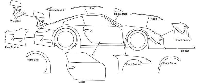
Front Fender Design
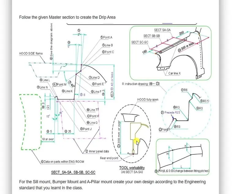
By using the given drawing inputs and Fender skin data, the front fender with Drip area, bumber mount, Sill mount, Cowl mount, A pillar mount is designed and modelled.
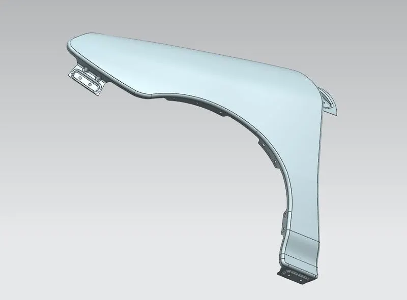

1. Drip Mounting
Drip Mounting is used to mount the front fender with the engine compartment. It is the main mounting among all of the mountings of the front fender.
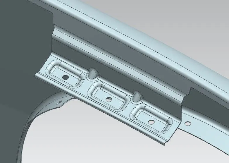
2. Bumber Mounting
It is used to mount front bumber with the front fender. Bumber is used to reduce the impace force.
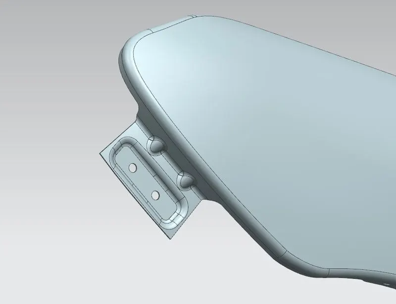
3. Splash Cover Mounting
Splash cover mounting is used to mount the splash cover which is used to prevent sand, mud, rocks, liquids, and other roads spray from being thrown into the air by the rotating tire.
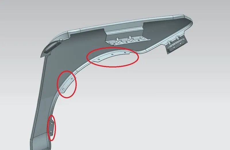
4. Sill Mounting
It is used to mount the front fender with sill. The rocker panel, or sill, is the part of the car traditionally running between the wheel-arches beneath the doors.
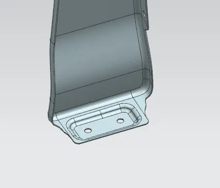
5. A pillar Mounting
A-Pillar mounting is also called as body mounting. It is used to mount the Front fender on the body of the vehicle.
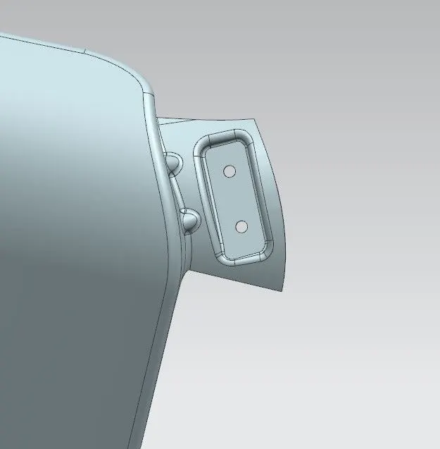
Design Parameters
1. Offset curve in face - to create offset curves on one or more faces from connected edges or curves on the surfaces. The offset curves can be associative.
2. Curve on Surface - to create a surface spline directly on a face or faces of one or more surfaces. With Curve on Surface splines, you can define tangent hold lines for a transition surface or blend, or define trim edges. You can create a Curve on Surface spline instead of projecting curve on a surface.
-
Constrain surface curves to other objects using G0, G1, and G2 continuity.
-
Constrain curves in isoparametric or sectional directions.
3. Trim Sheet - to trim sheet bodies to intersecting faces and datums, and projected curves and edges.
4. Law Extension - to extend an existing surface or sheet based on the laws for distance and the angle of the extension.
5. Datum Plane - to create a planar reference feature to help define other features, such as swept bodies and features at angles to the faces of target solids. Datum planes can be associative or non-associative.
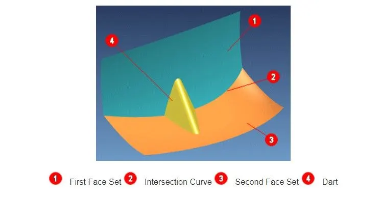
6. Intersection Curve - Creates intersection curves between two set of objects.
7. Face Blend - to add tangent and curvature continuous blend faces between two or three sets of faces.
8. Dart - This function lets you add a dart feature along the intersection curve of two sets of faces.
9. Projected Curve - to project curves, edges, and points onto faces, faceted bodies, and datum planes.
10. Emboss - Modifies a body with faces made by projecting a section along a vector. Emboss features are useful for stiffener and locator objects.
11. Extend Sheet - to extend or trim a solid or sheet body.
12. Sew - to join two or more sheet bodies into a new single sheet body. If the collection of sheet bodies encloses a volume, a solid body is created.
13. Thicken - to offset one or more connected faces or sheets into a solid body.
14. Edge Blend - to round sharp edges between faces.
Conclusion
Thus the front fender of the car using NX cad by given Fender skin data and drawings is modelled and the results are obatined.