Fender Design
FENDER DESIGN
AIM:-
- From the FENDER's provided Class-A Surface, we must modify the model's design and add a few new features that are:
- Bumper
- Drip
- A-Pillar
- Sill
- Baffel
COMMANDS USED:-
- Offset in face
- Curve on surface
- Trim sheet
- Law Extension
- Intersection plane
- Datum plane
- Sketch
- Face blend
- Bridge curve
- Projected curve
- Emboss
- Edge Blend
- Sew
- Dart
- Thicken
INTRODUCTION:-
- FENDER:
- The portion of the car that encloses the wheel is called the FENDER. The fender's main function is to stop rolling tires from launching sand, mud, gravel, etc. into the air, which could endanger pedestrians.

fig(1)- [Car Front Fender]
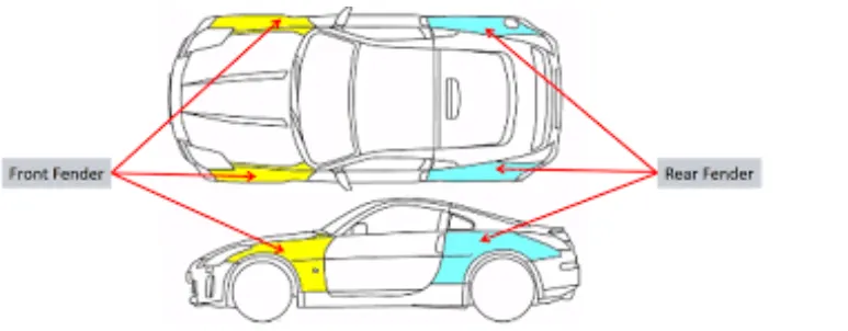
- There are two types of fender in a car body, front fender and rear fender as shown in fig(2).
fig(2)
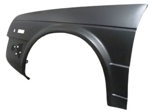
- There are two varities of Fenders: Full Bumper and Half Bupmer. These days, most fenders are half bumper style. As two half bumper style fender can be produced from a single blank, the cost of the sheet metal blank is decreased. In addition, this results in less scrap.
DESIGN FEATURES OF FENDER:-
fig(3)
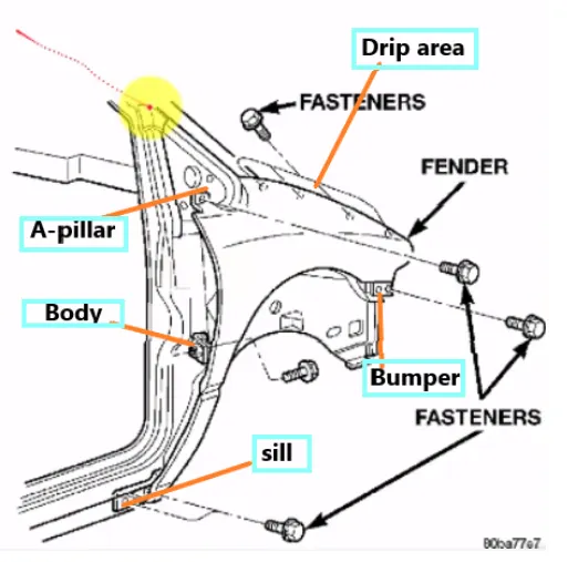
- Mounting Area:
- Bumper
- Drip
- Sill
- A-Pillar
- Baffel
BUMPER:
- The bumper mounting area is used to fix the plastic bumper to the fender with help of the fasteners.
DRIP:
- This is the crucial fender mounting unit, because of its connection to the engine comparment. The fender must adhere to several design guidelines.
- We must first leave 200-300 mm for the cowl top while designing the drip region.
- To place the headlights, we must leave at least 150mm in front when designing the fender.
- The cowl top part consists of a wiper motor and its instruments.
SILL:
- A Sill is a floor support panel located directly under the bottom of the door that can be used to connect the floor to the body. The lower end of the fender is mounted on the sill pack frame to strengthen the fender panel, so the sill mount is designed with holes and relief. M5 fasteners are used to fix the fenders on the sill body.
BAFFEL MOUNTINGS:
- Baffel mounting or mudguard are clip-fit types of mounting on the inner side of the fender arch over the tyre. It protects the car engine compartment and pedestrians from causing injuries from chip-out debris on the road when the car is in motion. They are mounted on the fender using special type of locking clips which are made up of plastics.
A-PILLAR AREA:
- The A-Pillar is the structural pillar that combines the body with the roof. This makes the sides of the windshield rest. Front fenders are fastened to the A-Pillar to form a robust structure.
FENDER MANUFACTURING PROCESS:-
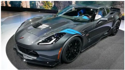
- The purpose of the fender is to prevent liquids, rocks, mud and other objects from being thrown into the air or onto pedestrians by rotating wheel. The shape of the fender is aerodynamic to reduce the air drag.
fig(4)
- Manufacturing process of the fender majorly involves these operations:
- Embossing
- Bending
- Cutting and Blanking
EMBOSSING:
- Embossing is a metal forming process for producing raised or sunken designs or relief in sheet metal using matched male and female roller dies, theoretically with no change in metal thickness, or by passing sheet or a strip of metal between rolls of the desired pattern.
BENDING:
- Metal bending is a process by which metal can be deformed when applying force to the subject, which causes it to bend at an angle and form the anticipated shape, which often results in it being in a 'V' or a 'U' shape. This is done through the application of force on a workpiece. The force on the workpiece can be mechanical, pneumatic or hydraulic.
CUTTING & BLANKING:
- Cutting processes are those in which a piece of sheet metal is separated by applying a great shearing force to cause the material to fail, Blanking is sheet manufacturing process in which a flat, geometric shape is created by feeding a coil of sheet metal into press and die in this process, the blank is punched out from the large metal sheet.
TYPES OF BUMPER:
- FULL BUMPER:
fig(5)
- HALF BUMPER:
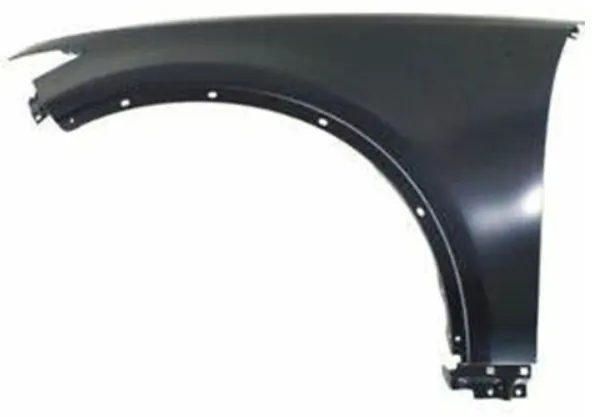
fig(6)
MAIN CONSIDERATION:-
- DRIP AREA:
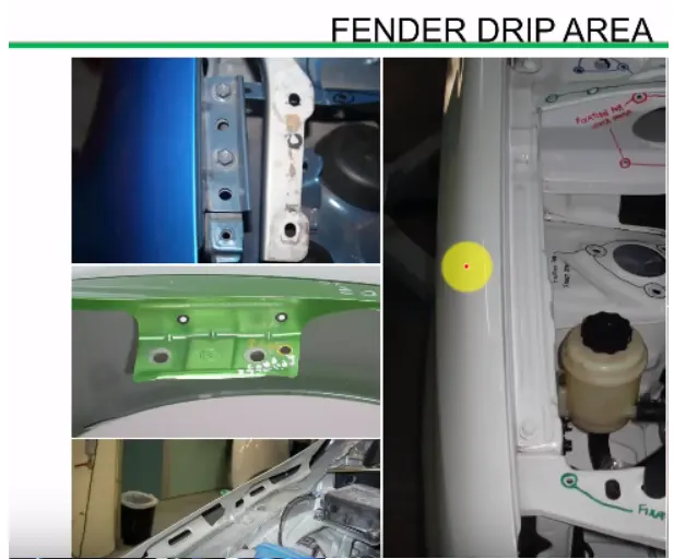
fig(7)
MASTER SECTION FOR DRIP AREA:-
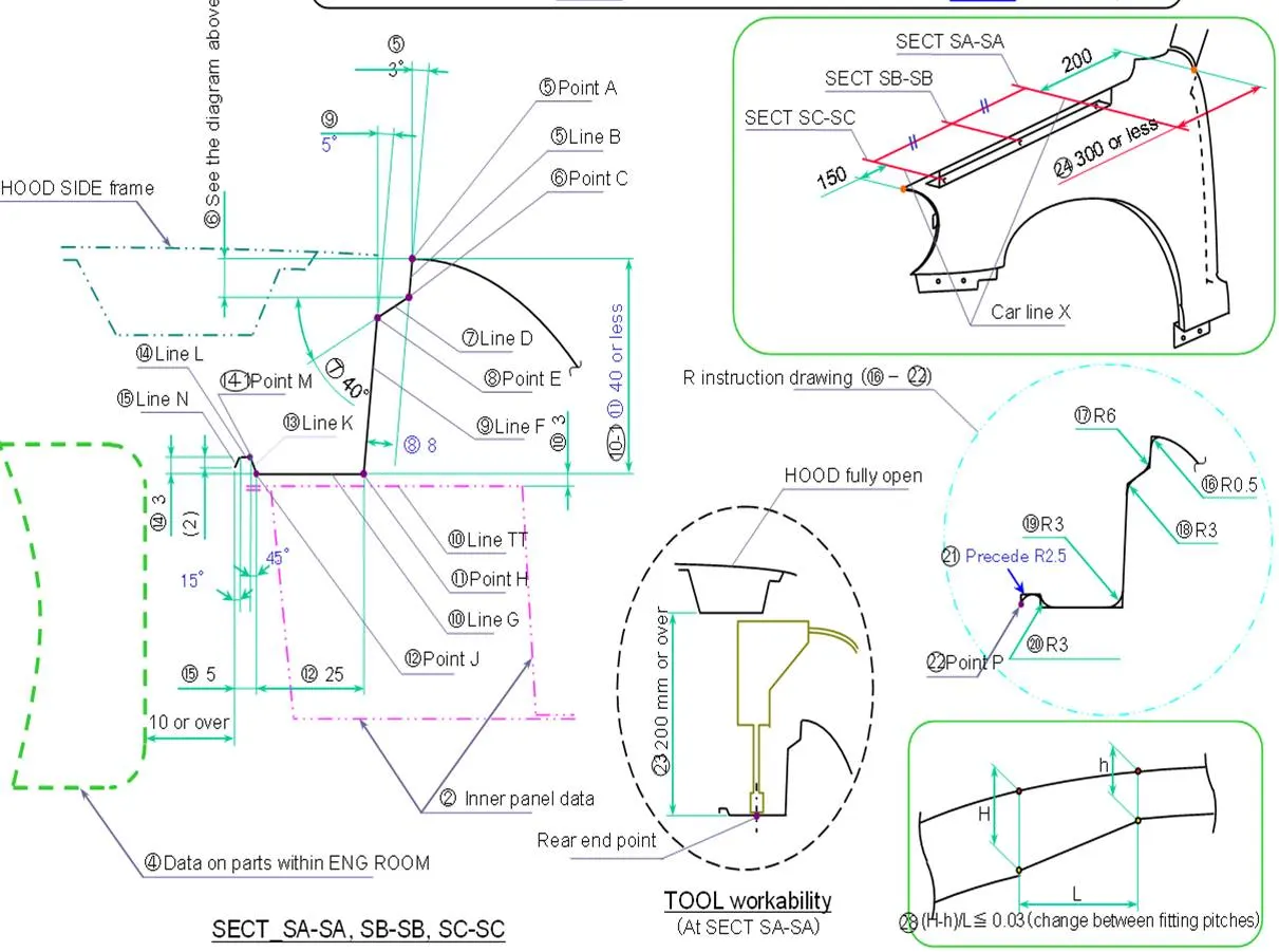
fig(8)
DESIGN METHODOLOGY:-
- CLASS-A SURFACE:
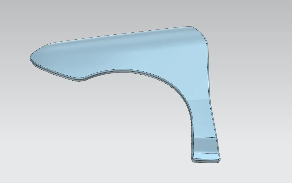
fig(9)
- DRIP AREA DESIGN:
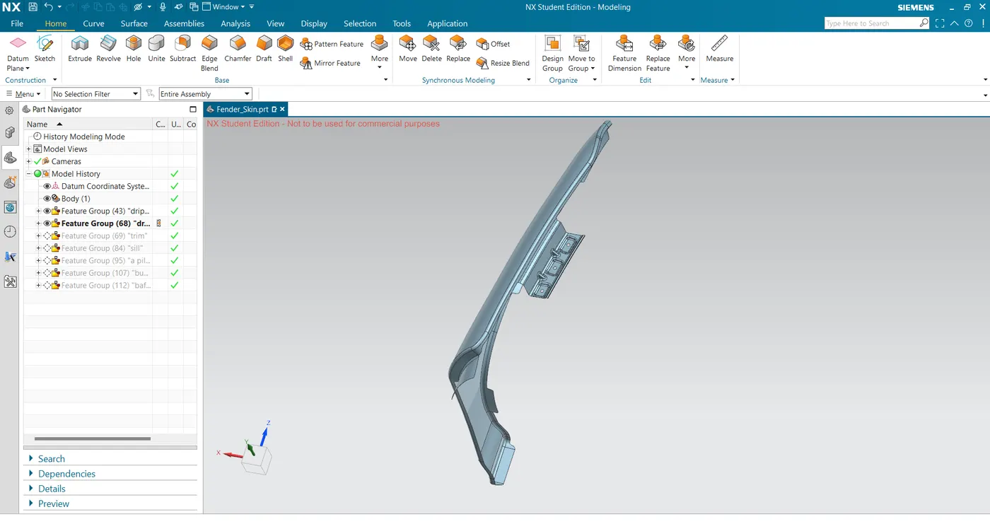
- Drip area mounting is the crucial part in the fender. This mounting is attached to the engine compartment of the car. Fender drip area is mounted via weldnuts to the engine compartment.
fig(10)
- The height of drip area mounting should be less than 40 mm so that it reduces the springback effect during manufacturing and reduce NVH issues during vehicle movement.
- Mounting screw holes of dia 5mm and locator pin holes are created for mounting guidance.
- It should be distanced atleast 150mm from the front side and 200mm from the rear side.
- Ribs are to be provided in order to increase the strength of the mounting part.
- Embosses are created as per design standards for proper fixation.
- A-PILLAR:
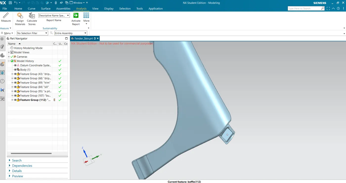
- The A-Pillar area mounting depends upon the A-Pillar of the car.
fig(11)
- BUMPER AREA DESIGN:
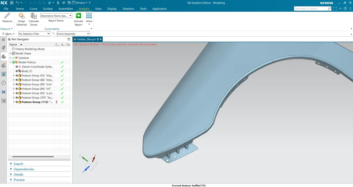
- This is designed by consulting the bumper design team to design the bumper and fender assembly fixation.
fig(12)
- SILL AREA MOUNTING:
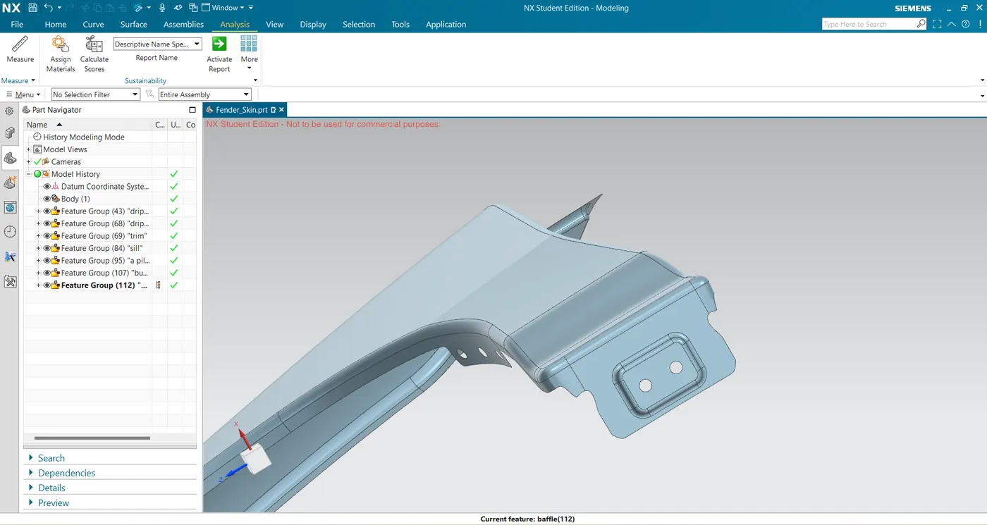
- Sill area mounting is also an important mounting part. This area mounting is basically on the bottom of the fender. The mounting part should be created such that the fender is firmly attached to the sill to avoid NVH issues.
fig(13)
- BAFFEL AREA MOUNTING:
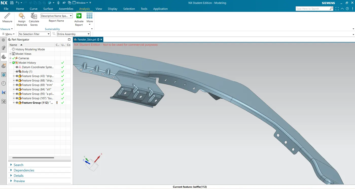
fig(14)
- At last use the THICKNESS command of .75mm to obtain the solid body.
3-D ORIENTATIONS:-
- ISOMETRIC VIEW:
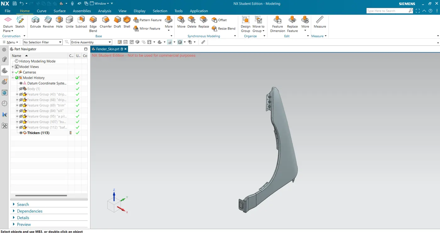
fig(15)
- FRONT VIEW:
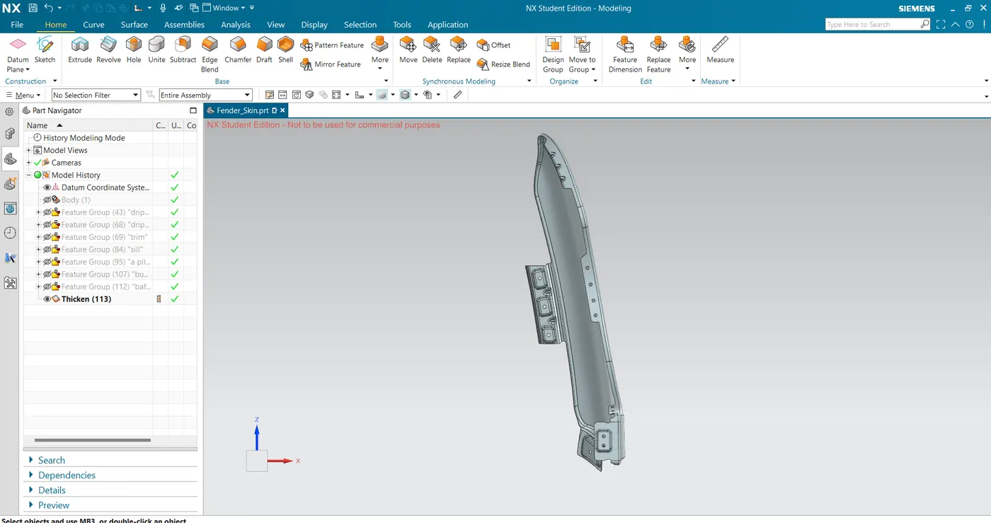
fig(16)
- SIDE VIEW:
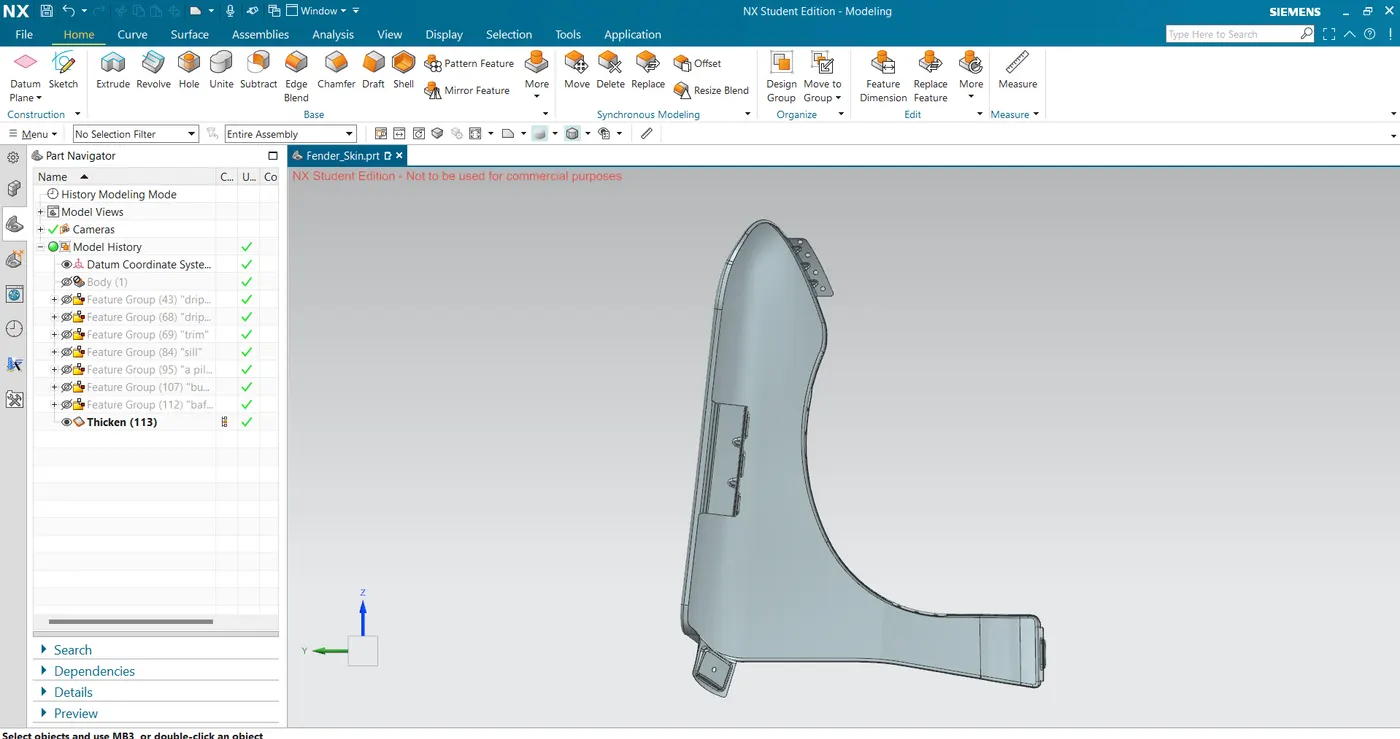
fig(17)
- TOP VIEW:
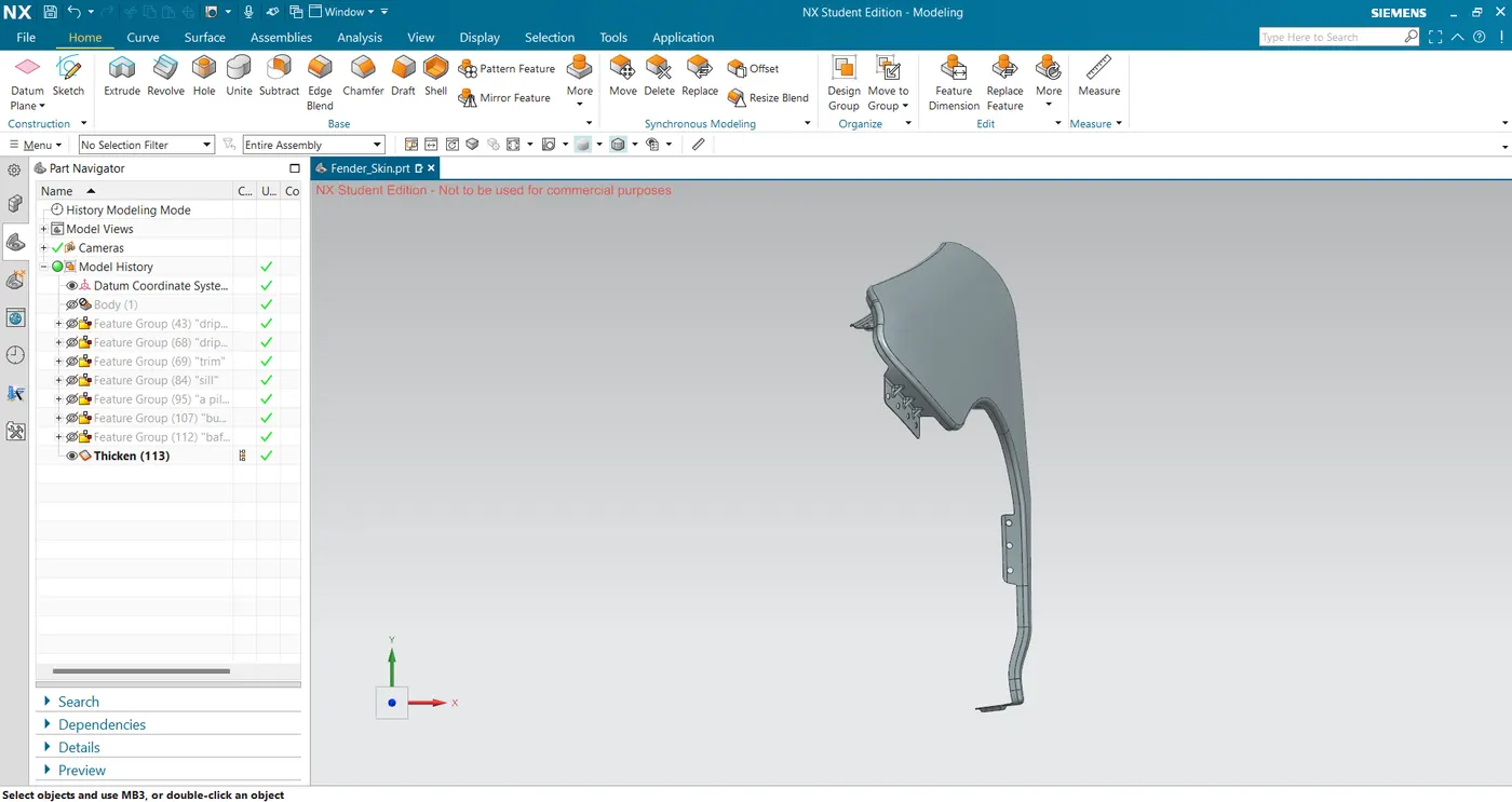
fig(18)
CONCLUSION:-
Vehicle Fenders are checked for wheel arch radius according to European rules and Front Half Fenders are designed using master section according to pedestrian safety and to protect engine commpartment next to vehicle.