Fender Design
AUTOMOTIVE FENDER
(i) Purpose
The primary purpose of fender is to prevent sand,mud,rocks,liquids and other road spray from being thrown into the air by the rotating tyre. When vehicle is moving, tyres pick up stones and other and hurl them in all directions. Fenders are basically present to prevent any injuries to the pedestrians and contain the motion of these particles
 .
.
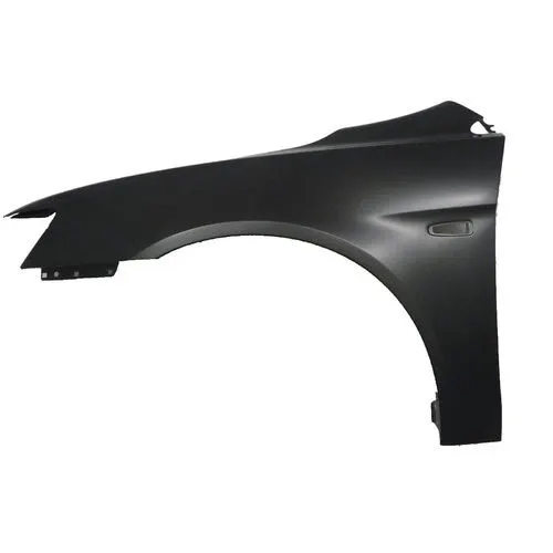
The above figure represents the front fender of an automotive car
(ii) Design requirements for fender (given master section for Drip area)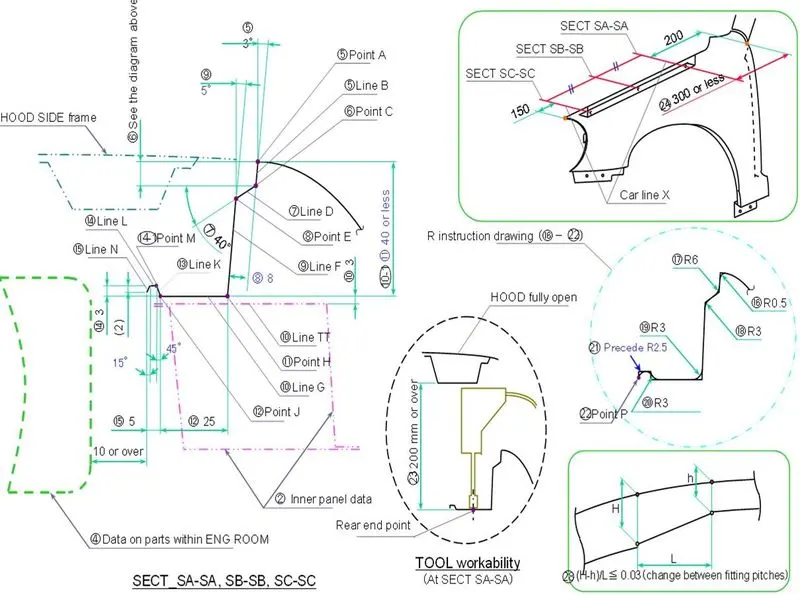
The above figure represents the design for fender drip area
- The 200mm distance is left for wiper cowl mount
- The 150mm distance is left for headlight housing
- The 3 deg draft (Line B) is for easy removal of component after stamping process.
- The 8mm length (Line D) is provided to prevent visibility of internal parts and fasteners of the engie compartment.
- The depth of fender drip (Pt A to Pt F) should be less than or equal to 40mm or less. This is because the Stamping process cannot produce fender drip surfaces with depth more than 40, even if it is manufacturable, it would cause springback problems.
- The surface length (line G) should be 25mm as it provides a clearnce of 200mm when the hood is in fully open condition. this clearance aides in positiong of fender using the tool.
- The distance between fender surface and engine room should be 10mm or more to avoid engine vibrations to the fender.
(iii) Manufacturing process
Fenders are manufactured using a method known as Stamping Process.
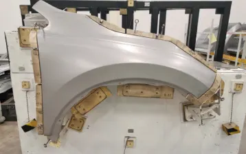
Metal stamping is a cold-forming process that makes use of dies and stamping presses to transform sheet metal into different shapes. Pieces of flat sheet metal, typically referred to as blanks, is fed into a sheet metal stamping press that uses a tool and die surface to form the metal into a new shape.

Stamping press machine
Fender
(iv) Designing mounts for Fender using NX Cad
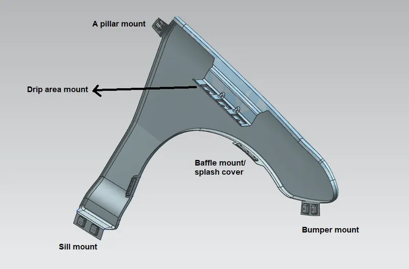
There are five mounts that are to be designed on Fender
(a) A pillar mount
(b) Drip area
(c) Baffle mount/splash cover
(d) Bumper mount
(e) Sill mount
Given Class A surface of Fender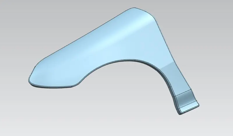
(a) A pillar mount
A pillar mount region assemles to the A pillar region of the car body and is created using law extension, embosses and fillets.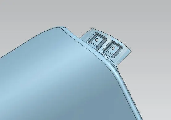
(b) Drip area mount
Drip area is created as per the given master section design. This region is either spot welded or bolted using slef tapping screws and is inflush with inner hood panel in closed condition of hood.
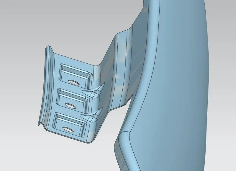
The ribs are created to provide strength to the drip area region. This feature is created using law extension, embosses & darts (for ribs).
(c) Baffle mount/splash cover
This region acts as cover for the wheel region. This feature is created using law extension & embosses.
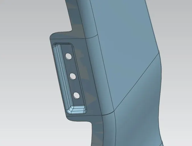
(d) Bumper mount
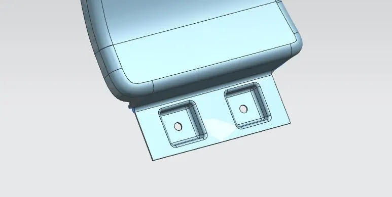
This region assembles to front bumper part of the car body. This feature is created using law extension & embosses.
(e) Sill mount
Sill mount region assembles to the sill portion of the car body (near the door). This feature is created using law extension & embosses.