Engine Wiring Harness Routing and Flattening in CATIA V5
OBJECTIVE
To route the wiring harness on the given Engine along with the necessary protective covering and to prepare a flattened view drawing in CATIA V5.
PROCEDURE
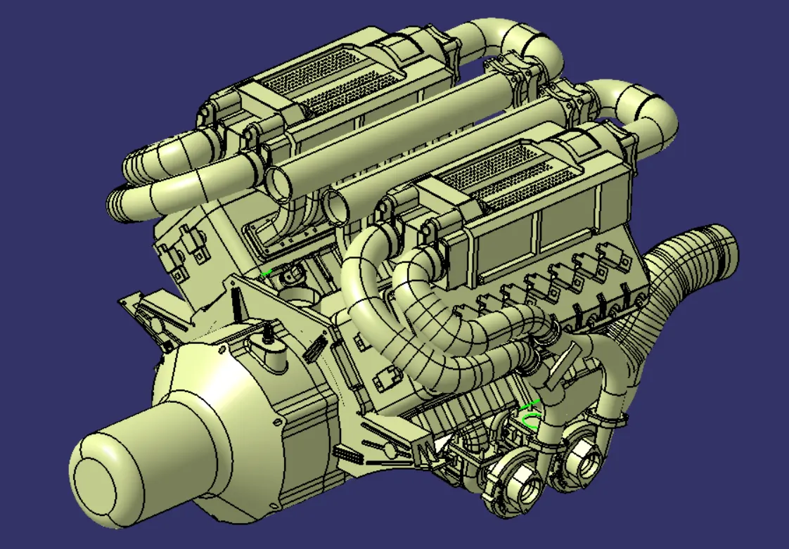
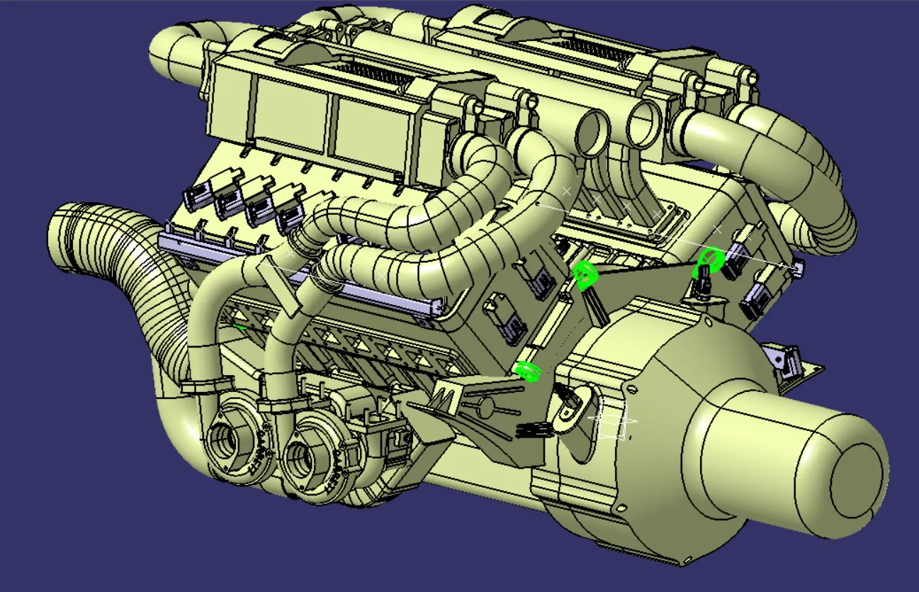
- The given engine is a V16 engine. Before we can route, we have to list all connection points that will house the connectors and thus would require a wiring harness connecting them. Upon close examination we can list the following connectors required:-
- 16 connectors (12 terminals) for fuel injectors
- 4 connectors (12 terminals) for camshaft position sensors
- 1 connector (12 terminals) for inter-connection and cavity clip
- 1 connector (2 terminals) for coolant temperature sensor
- 1 connector (2 terminals) for flywheel position sensor
- 1 connector (2 terminals) for crankshaft position sensor
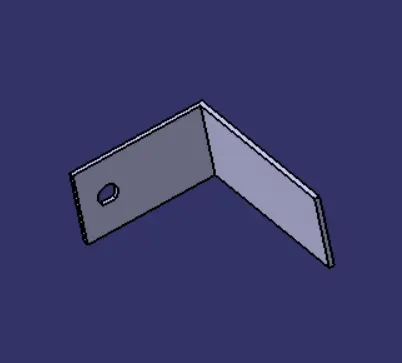
- L clip for mounting inter-connector.
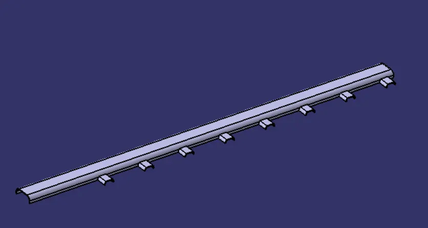
- In addition to connectors, we need two harness guiding channels. We are provided with channel top and bottom for one side and have to apply symmetry command for obtaining for the other side.
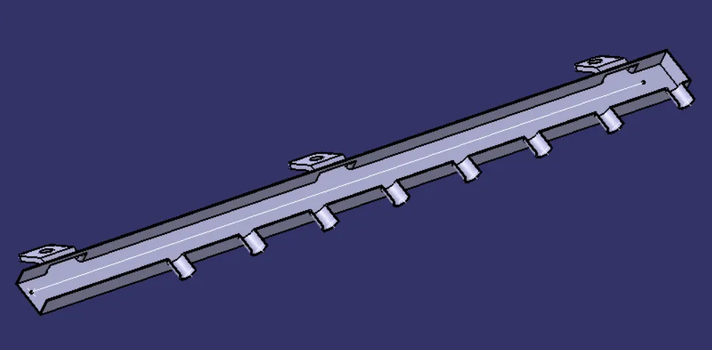
- For the next step, we would be required to define all the components we wish to use for the routing as an electrical component. This includes defining connectors and supports electrically and defining bundle entry points for connectors and channels.
- Defining Inter-connector
- First, in the electrical part design workbench, we use the define connector command
 to define the connector part number and terminal information.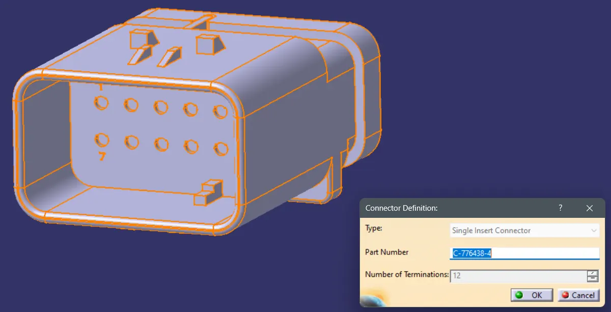
- Next, we create 3 points viz., the connector connection point, the bundle entry point, and the cavity connection point. We also create the axis system for connector connection and cavity connection.
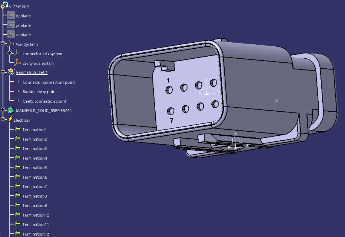
- As the final step, we use the define connector connection point command
 , define bundle entry point command
  , and define cavity connection point command
  to fully define the connector electrically.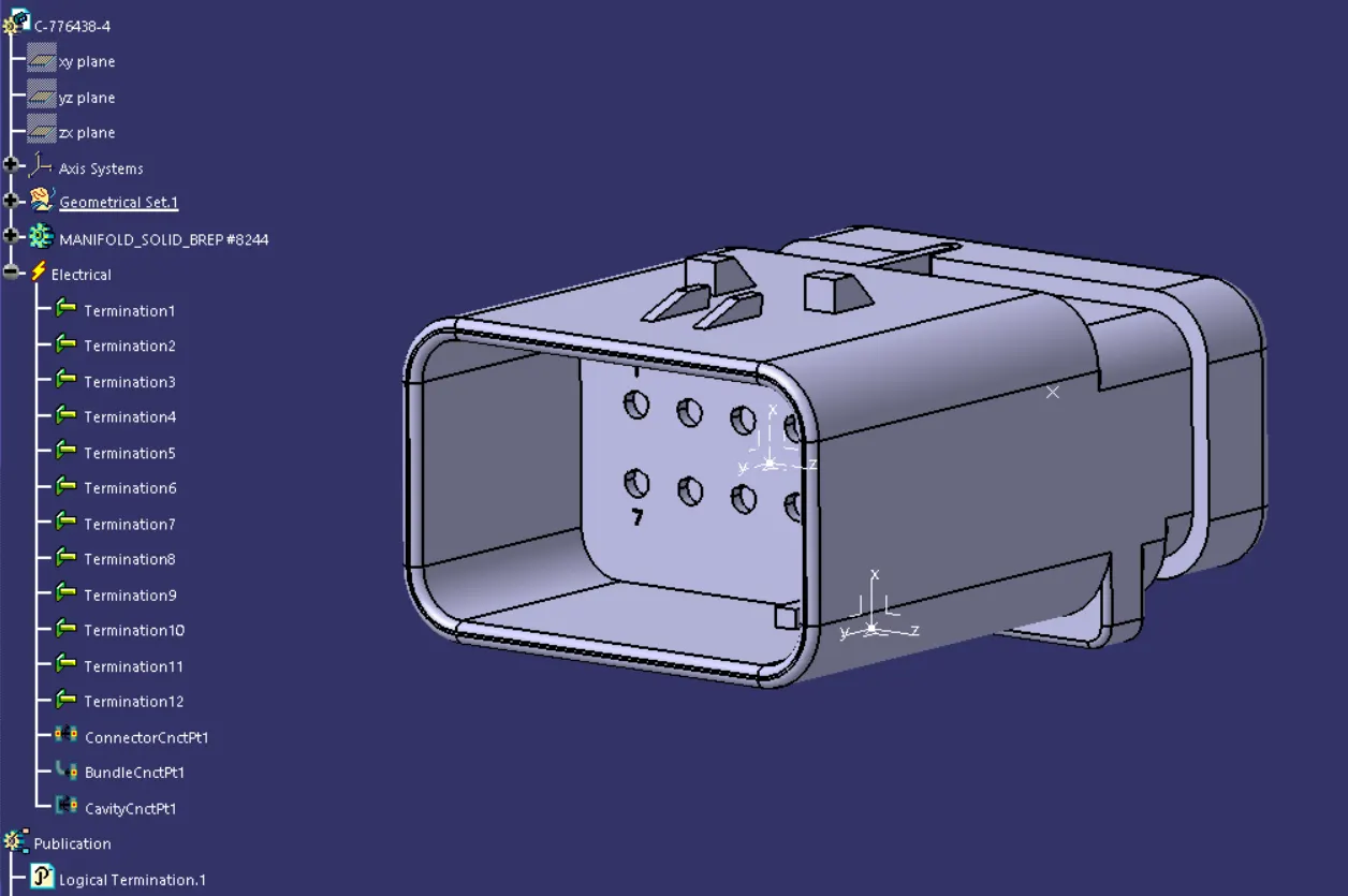
- First, in the electrical part design workbench, we use the define connector command
- Defining cavity clip
- We first, define the clip as an electrical mounting device.
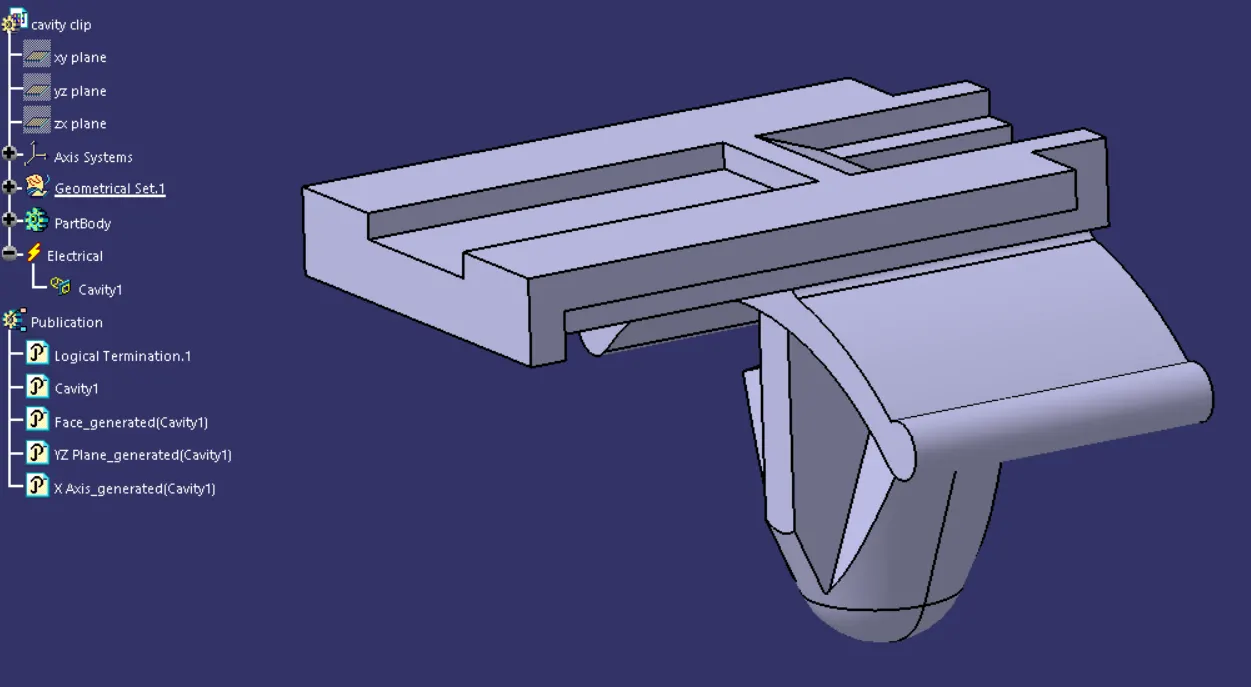
- Next, we create the cavity connection point and axis system.
- finally, we use the define cavity connection point command to define the cavity clip.
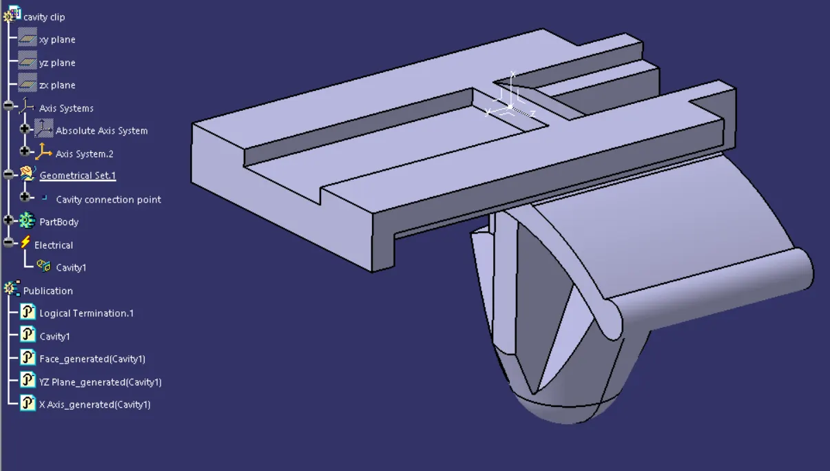
- We first, define the clip as an electrical mounting device.
- Defining 12-pin and 2-pin connectors
- First, in the electrical part design workbench, we use the define connector command to define the connector part number and terminal information.
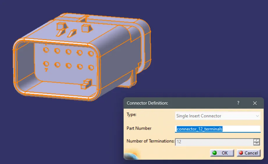
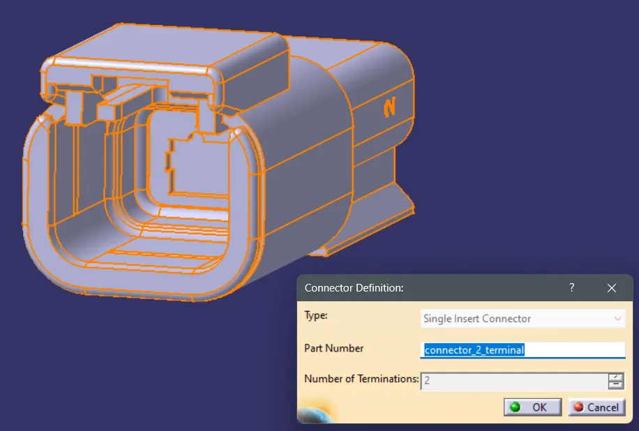
- Next, we create 2 points viz., the connector connection point, and the bundle entry point. We also create the axis system for connector connection.
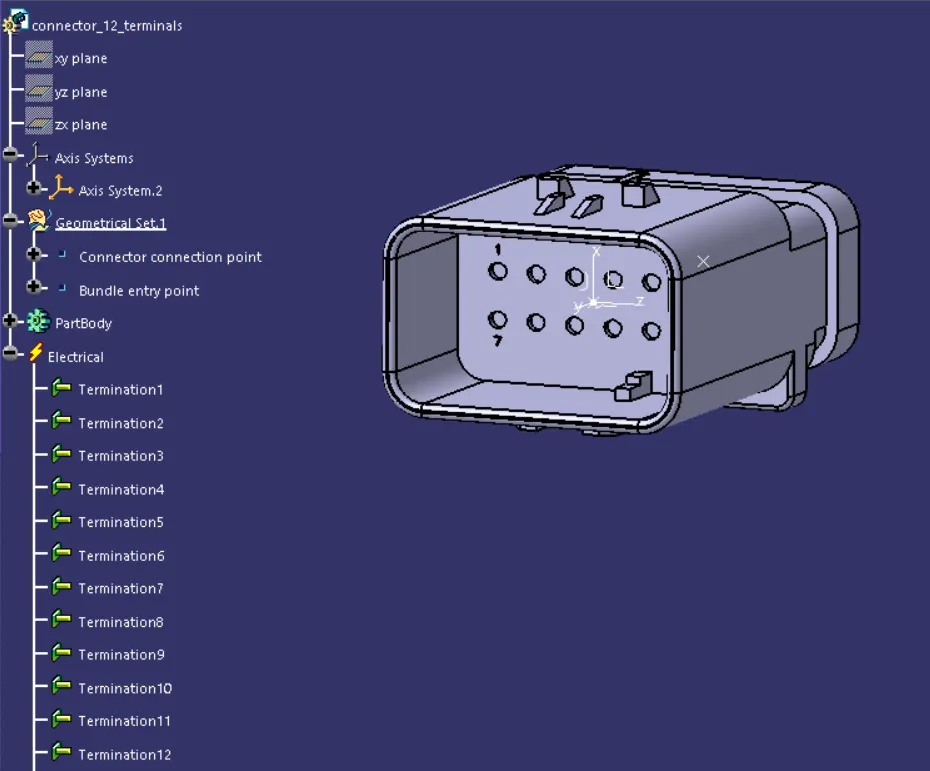
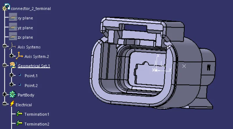
- As the final step, we use the define connector connection point command , and define bundle entry point command to fully define the connector electrically.
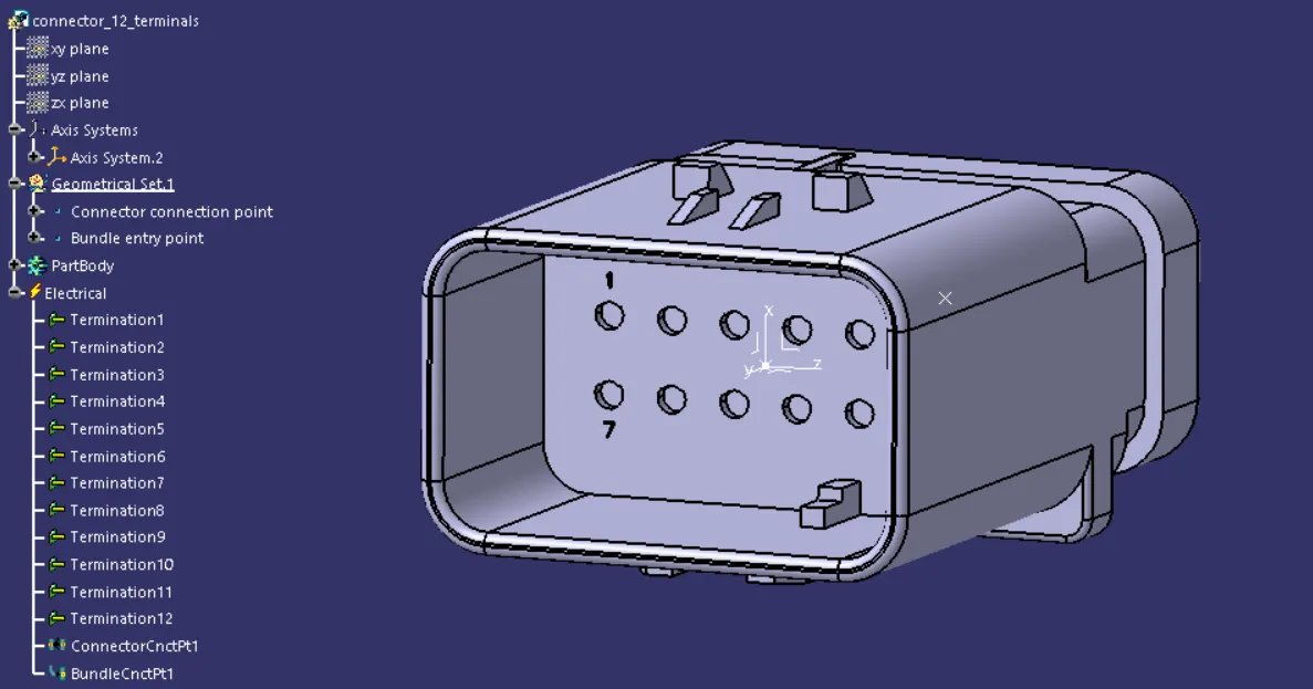
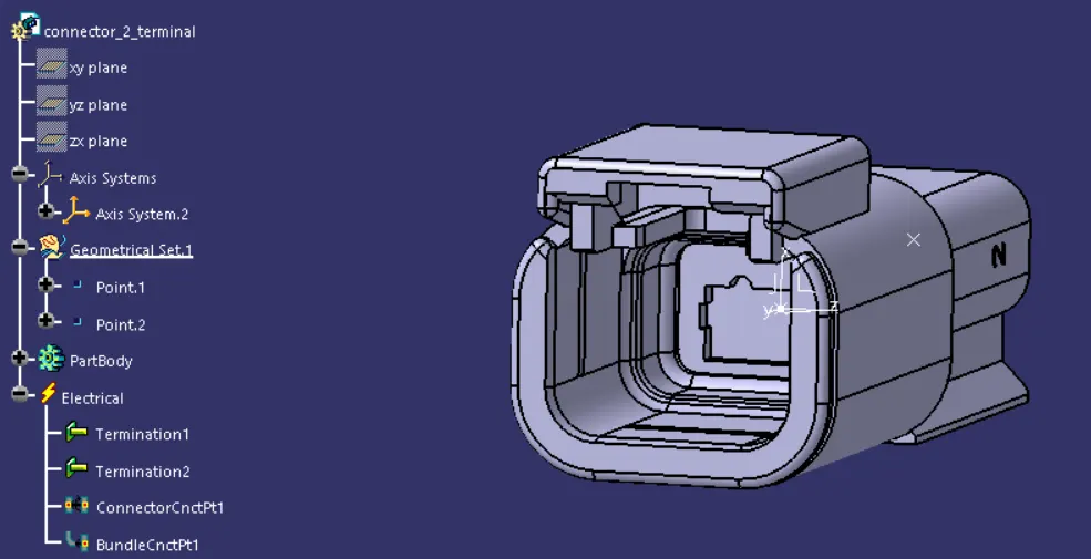
- First, in the electrical part design workbench, we use the define connector command
- Creating and defining support guide channels
- First, we need to create a symmetry of the given channel for the other side of the engine. We use the symmetry command in the part design workbench with the ZX plane as a reference. We repeat this for both channels (top and bottom) individually.
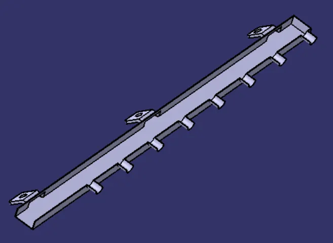
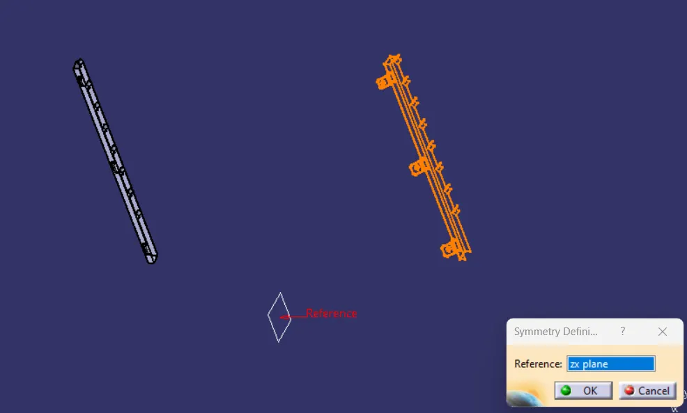
- Next, we create a line at the center of both bottom channels to serve as harness routing. We also create points at the center of the openings for harnesses.
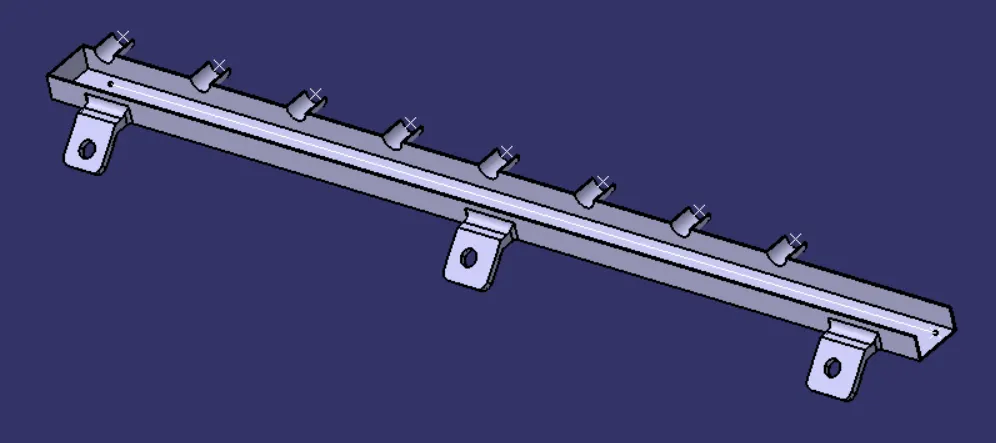
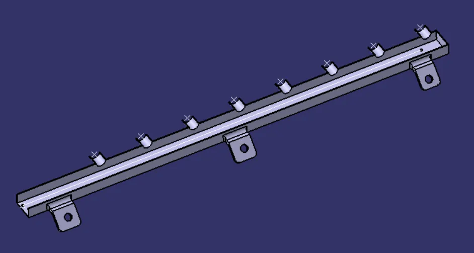
- Now, we define the bottom channels as support equipment and define all the bundle connection points to fully define them for use in routing.
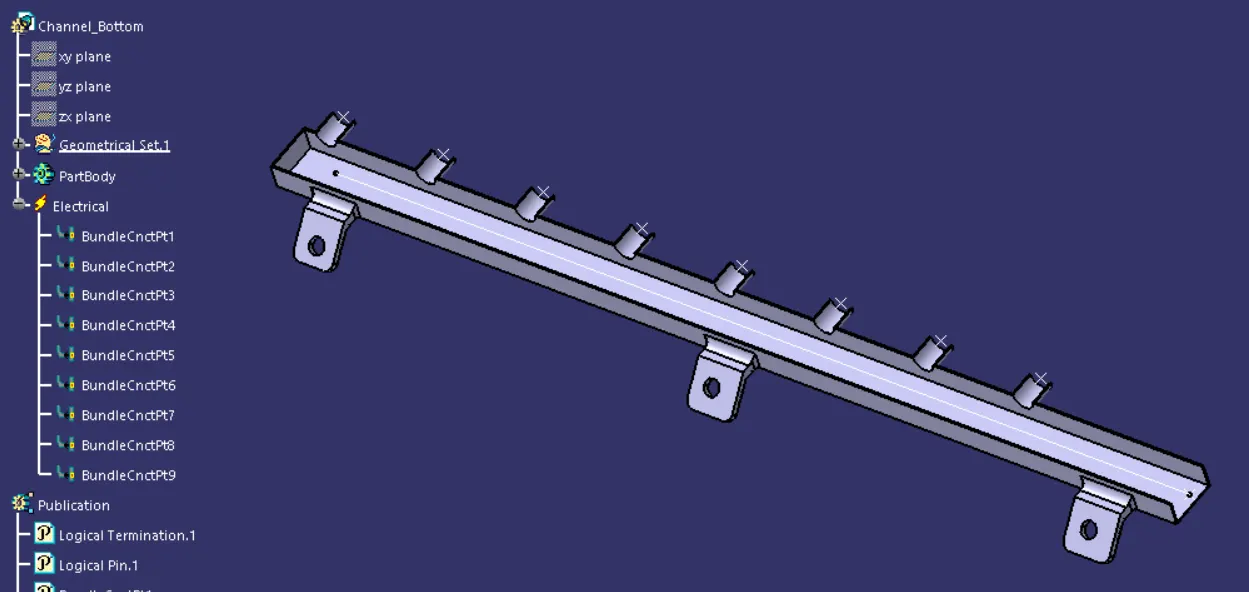
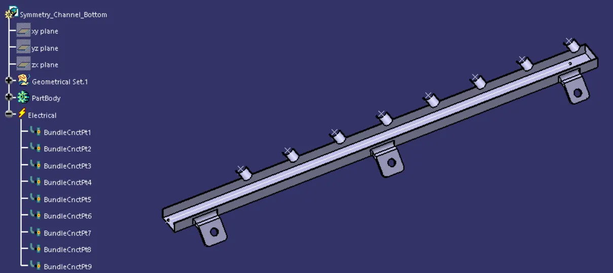
- First, we need to create a symmetry of the given channel for the other side of the engine. We use the symmetry command in the part design workbench with the ZX plane as a reference. We repeat this for both channels (top and bottom) individually.
- Defining P-clamp
- We create 2 points at the center of the openings and create 2 planes normal to the base and 3rd plane at the base.
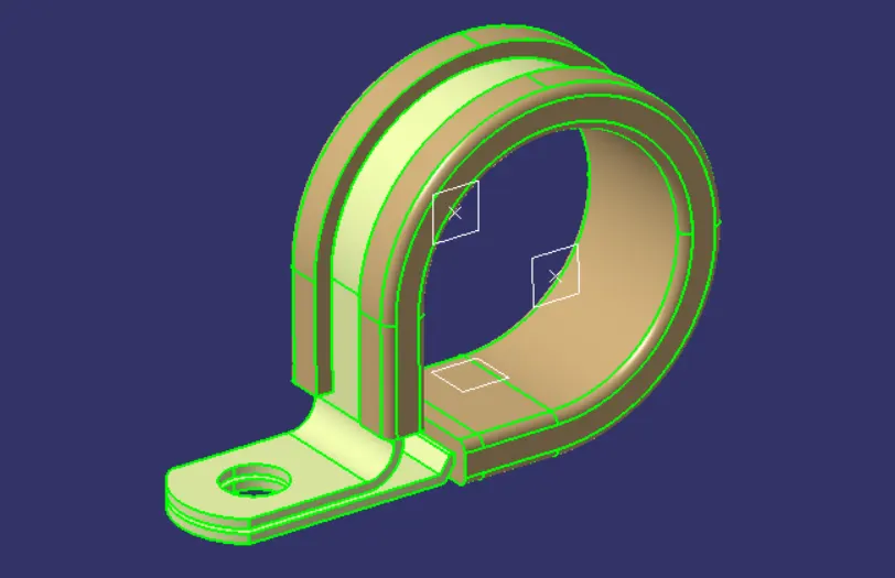
- We use the define support command to define the entry, exit, and base planes.
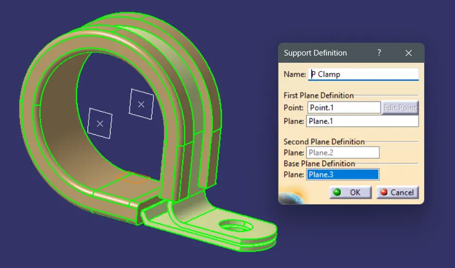
- We repeat the same for the other entry as well.
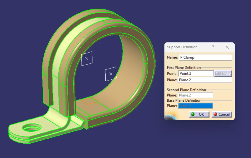
- The p-clamp is fully defined now.
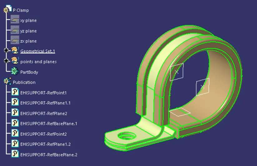
- We create 2 points at the center of the openings and create 2 planes normal to the base and 3rd plane at the base.
- Defining Inter-connector
- Now that we have defined all components required for routing, we create an assembly product, name it Engine_Wiring_Harness_Context assembly, and add the engine and L clip. We also create the Engine_Wiring_Harness_Geometrical_Bundle assembly which will house the connectors, channels, and the multi-branchable upon routing.
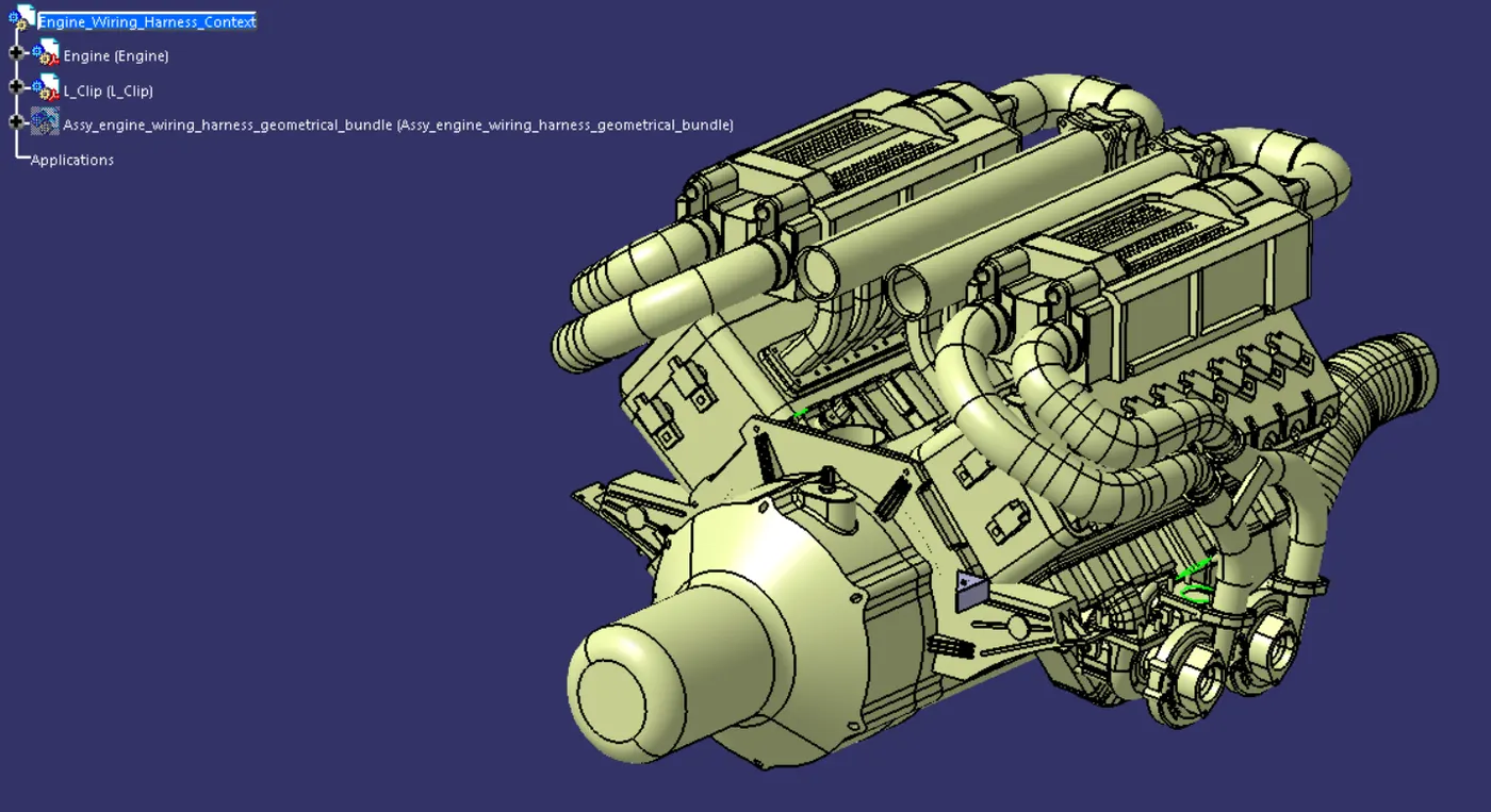
- Now, we open the Geometrical bundle in a new window and insert the engine, L clip, and all the required connectors. The engine and L clip will serve as a dummy for us to position our connectors and clamps and will be deleted after the positioning is final. In the assembly workbench, we move each connector and clamp to the required position using the move command to their final positions.
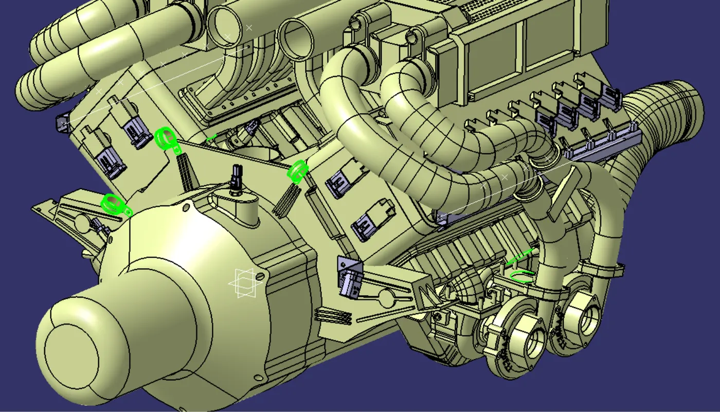
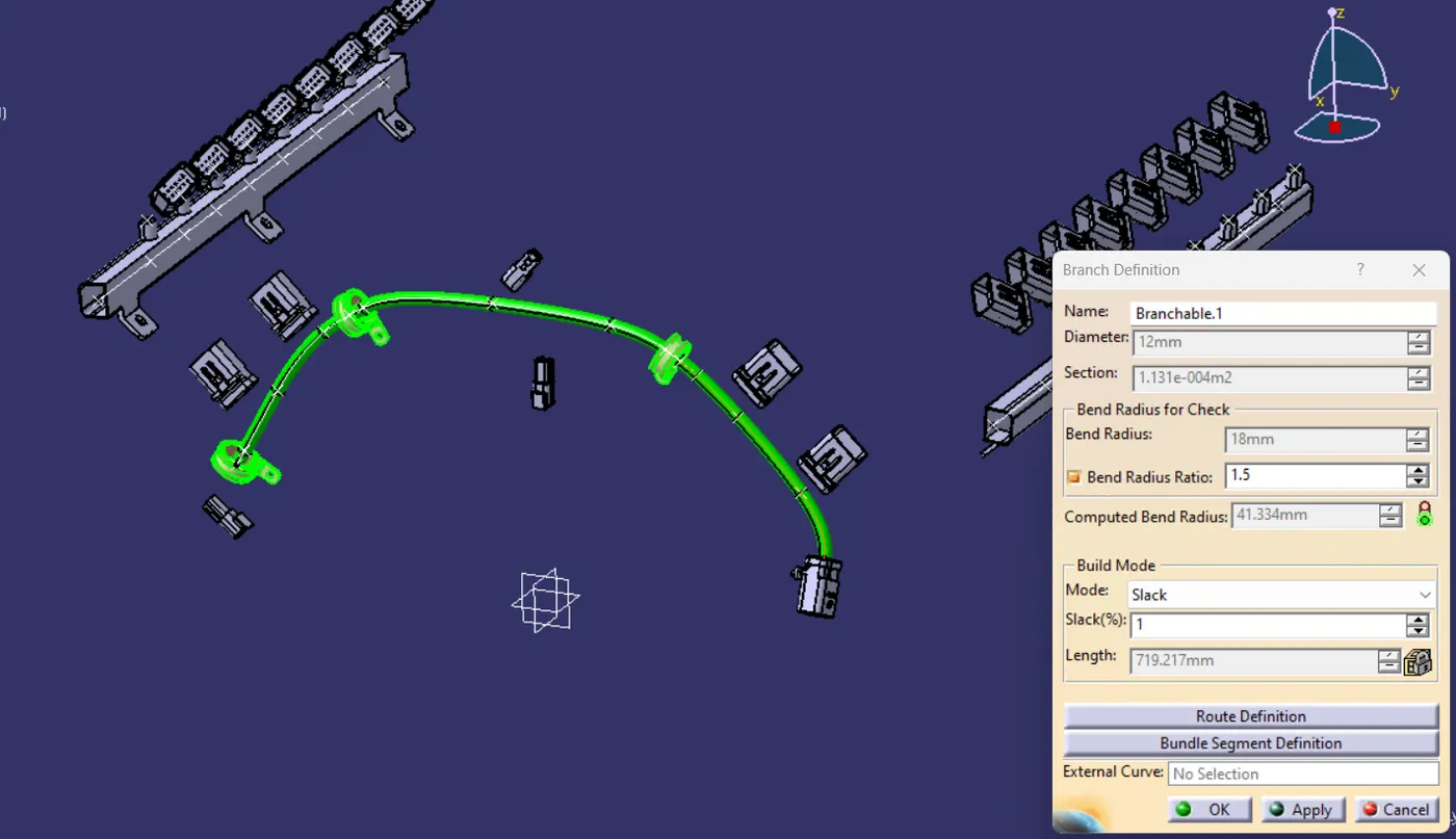
- Next, we move to the electrical harness assembly workbench and define the assembly as a geometrical bundle using the geometrical bundle command. Then we activate the multi-branchable command and create a branch definition to route the harness of the required diameter and slack percentage through the required connectors using the route definition window.
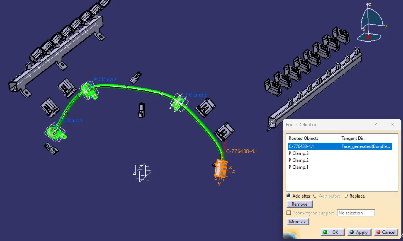
- We similarly connect each connector with the harness by creating a branch point and then joining it with the branch.
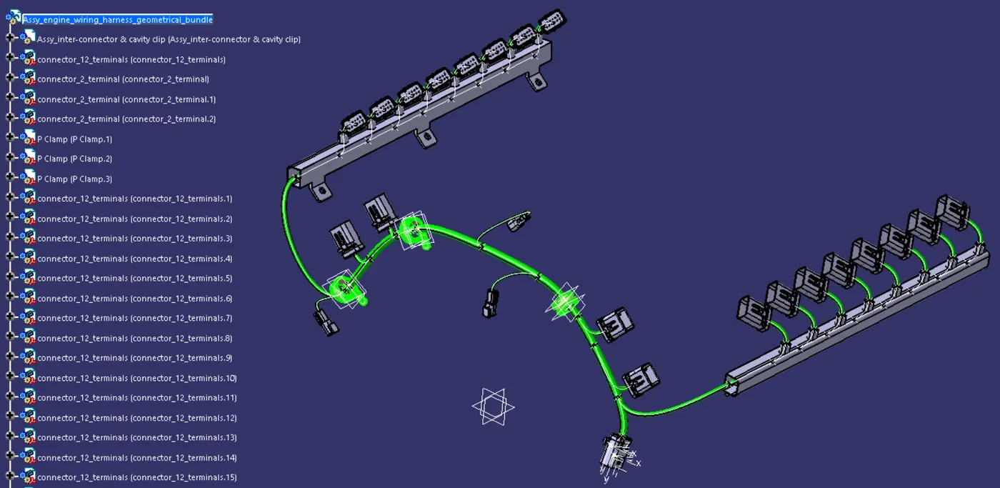
- After we have connected all the connectors, we check for bundle connectivity by using the search command under the Edit menu.
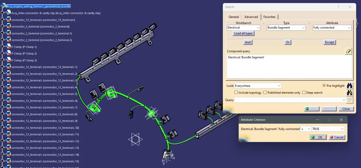
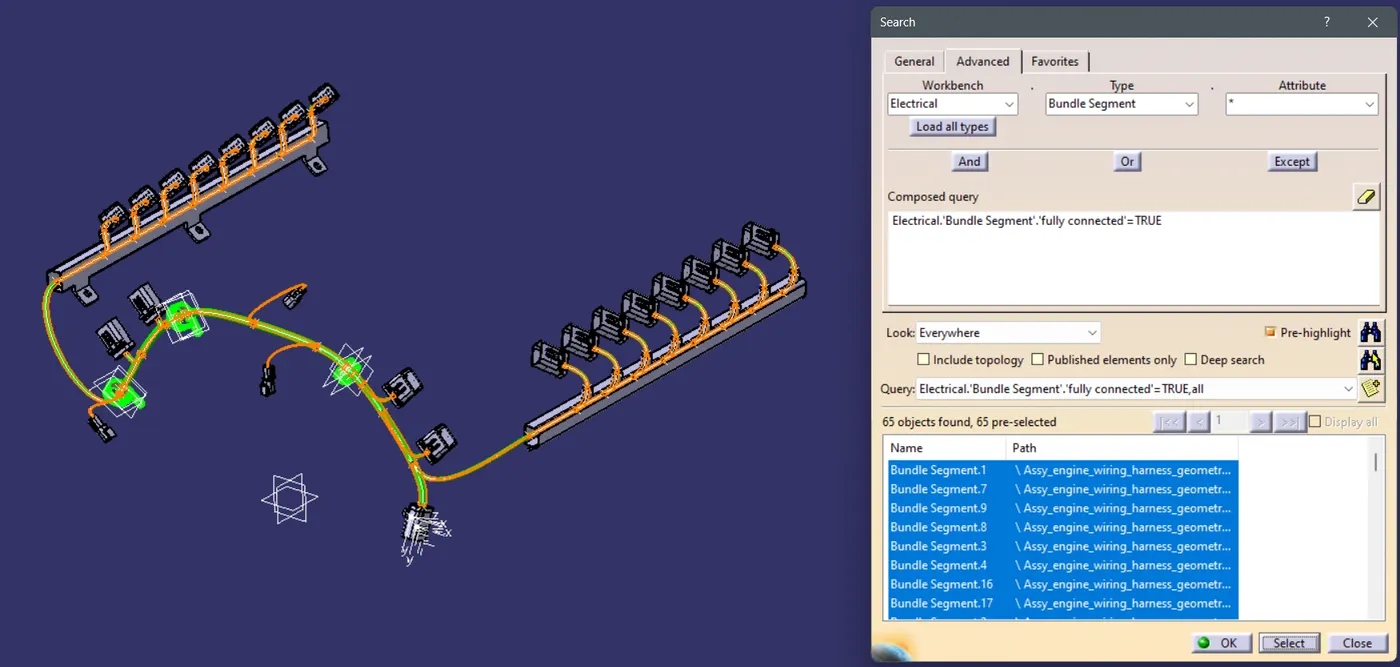
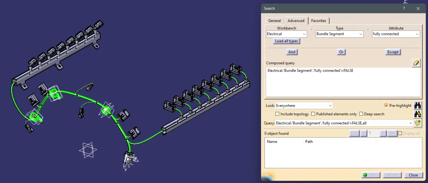
- Once all the branches are connected we use the protective covering command in the harness assembly workbench to add cot tubes of required diameter to the branches.
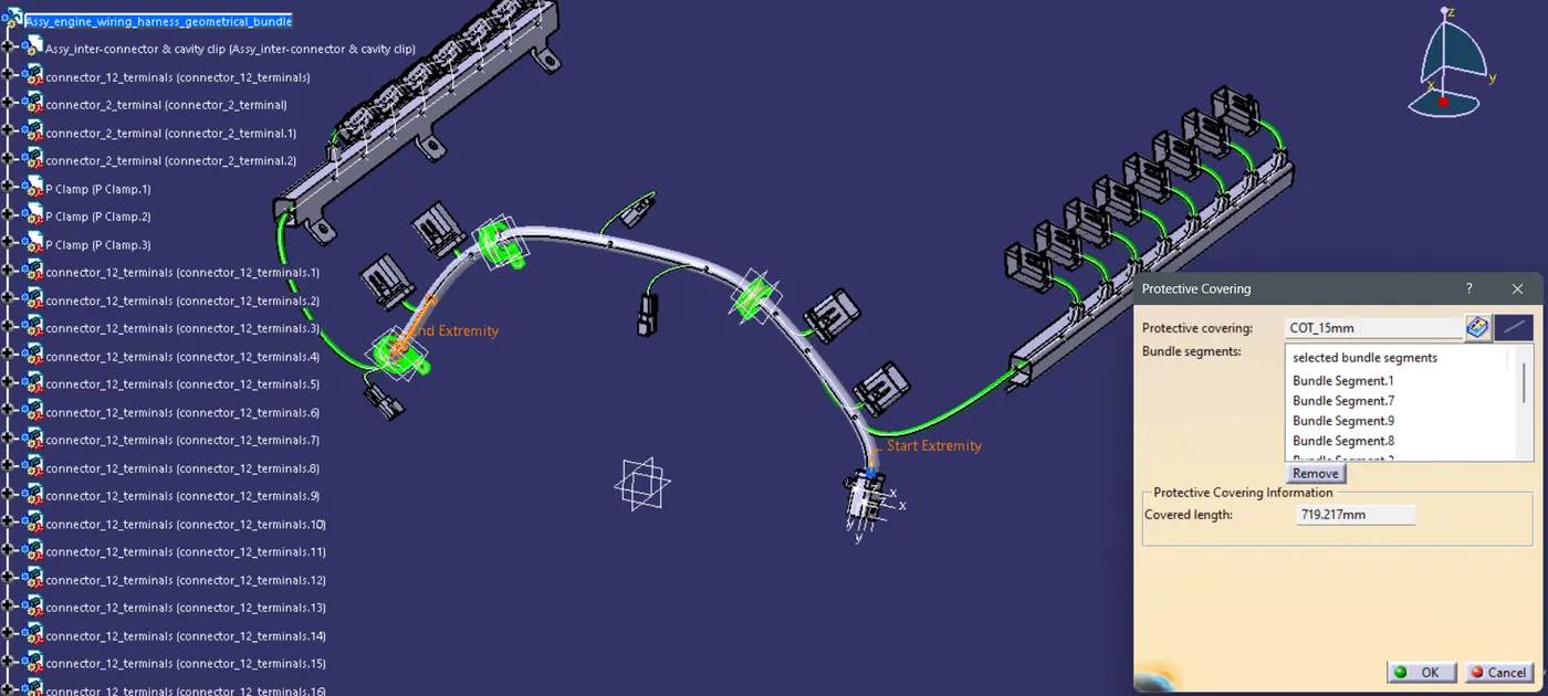
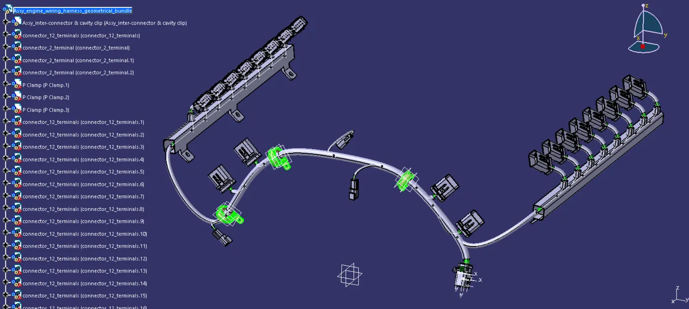
- For the final step, we delete the engine and L clip from the geometrical bundle assembly and save the product in the required folder. We then close the geometrical bundle product window and update the context assembly to get the final harness routing.
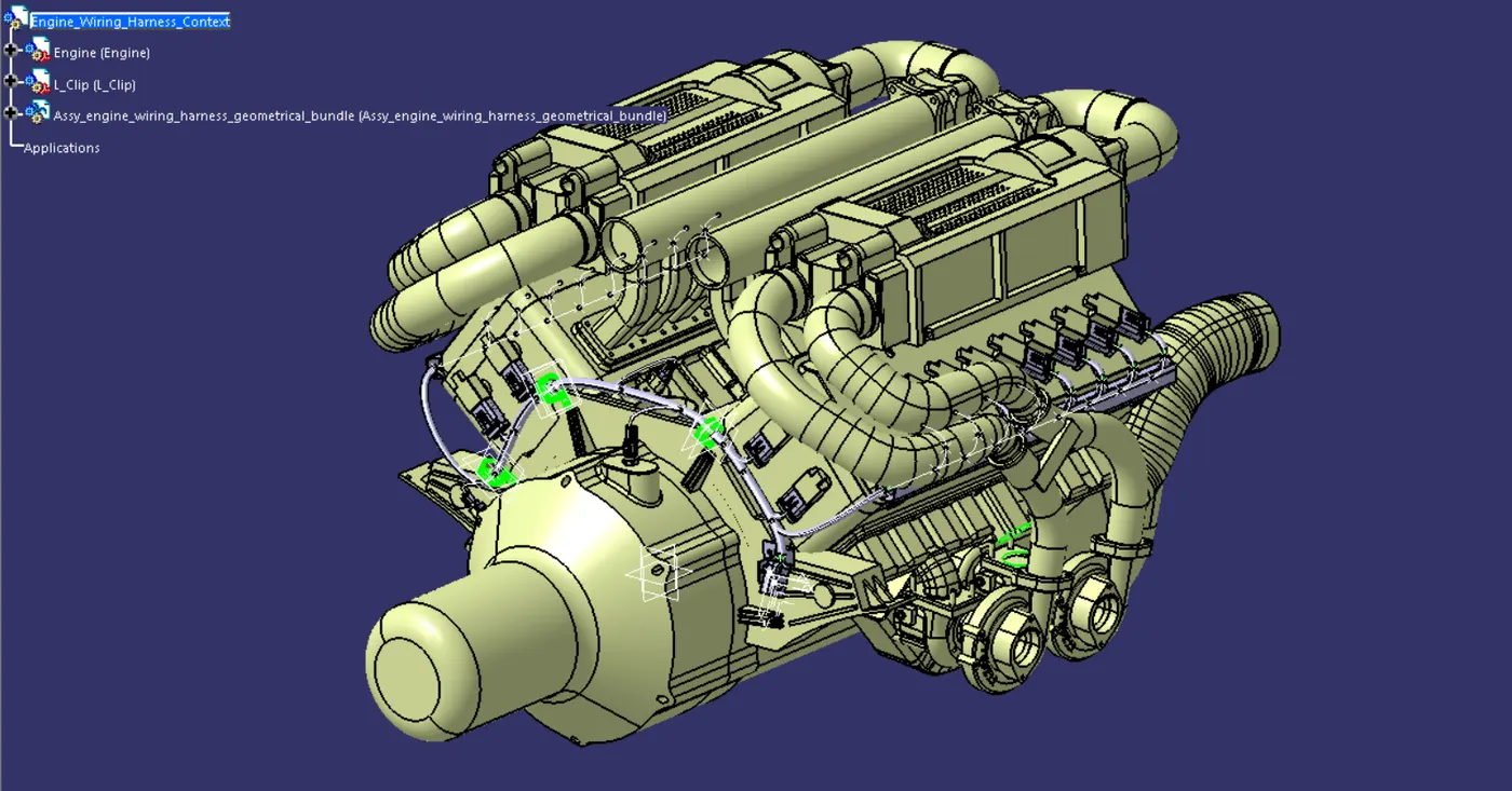
- Now, we open the Geometrical bundle in a new window and insert the engine, L clip, and all the required connectors. The engine and L clip will serve as a dummy for us to position our connectors and clamps and will be deleted after the positioning is final. In the assembly workbench, we move each connector and clamp to the required position using the move command to their final positions.
- Once the wiring harness routing is done, we flatten it before we can represent it in a drawing. For that, we create a new product file and give the name Assy_Engine_Wiring_Harness_Flattening product.
- Before we can import the geometrical bundle in the flattening assembly, we first have to configure the harness flattening parameters.
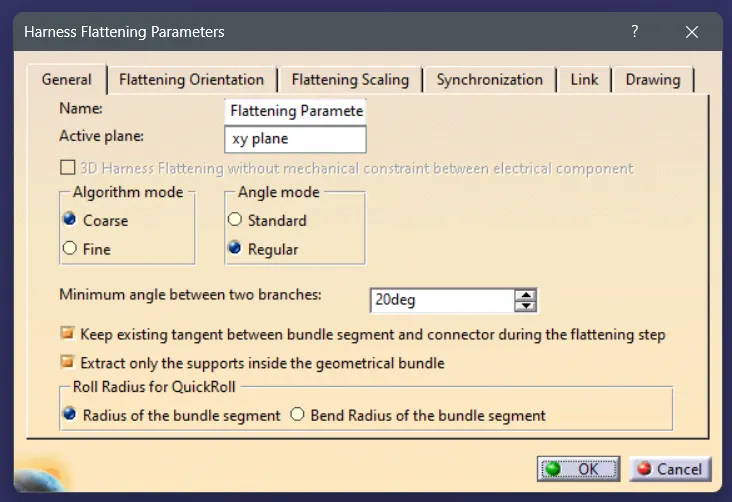
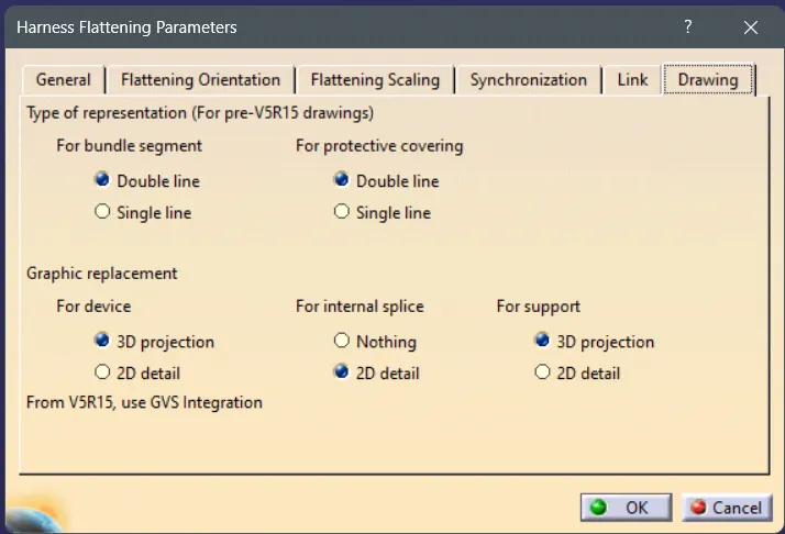
- Once the parameters are saved, the flattening commands are active. We use the extract command to import the geometrical bundle product into the flattening product.
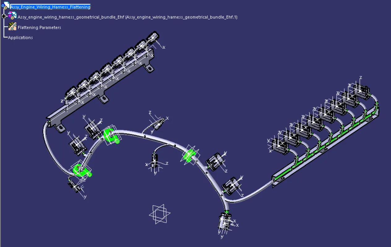
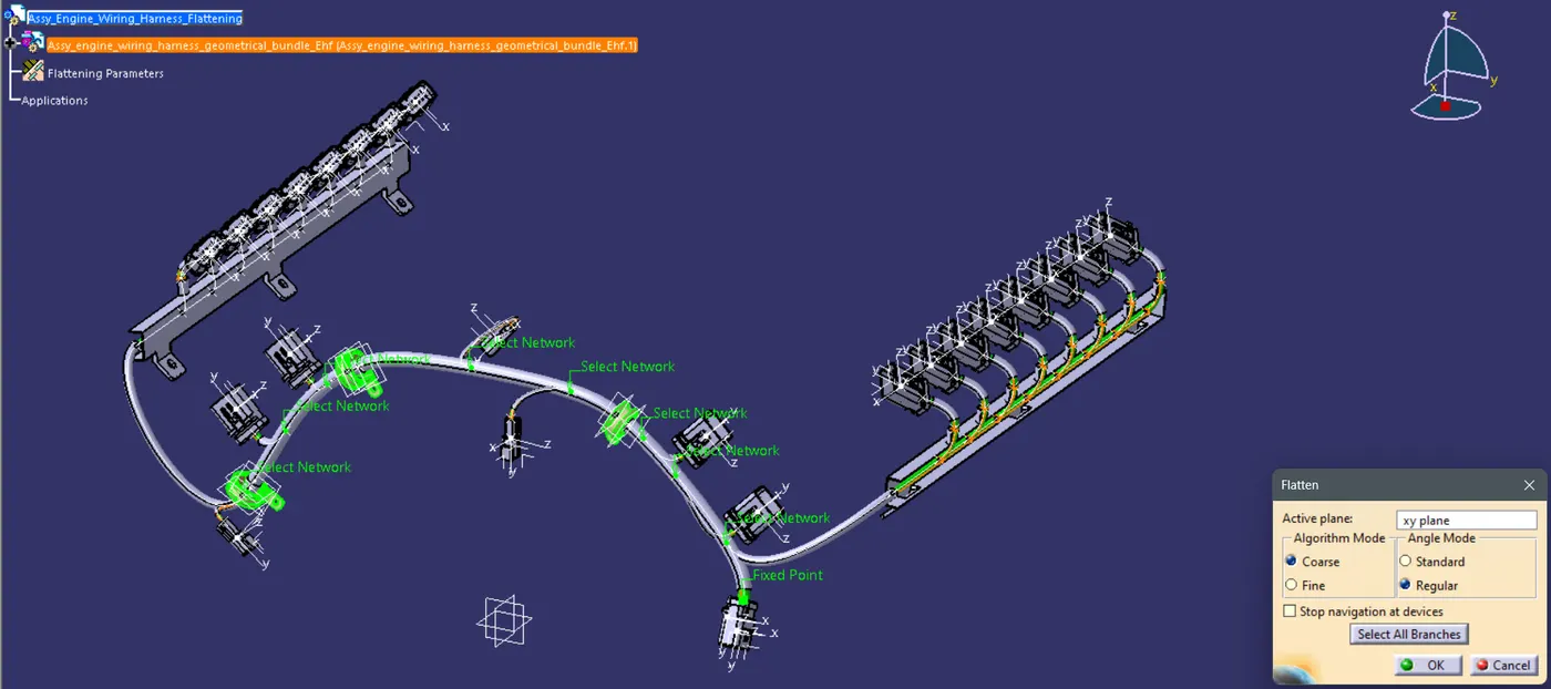
- Now we use the flatten command and select all branches to flatten the harness bundle in the provided plane.
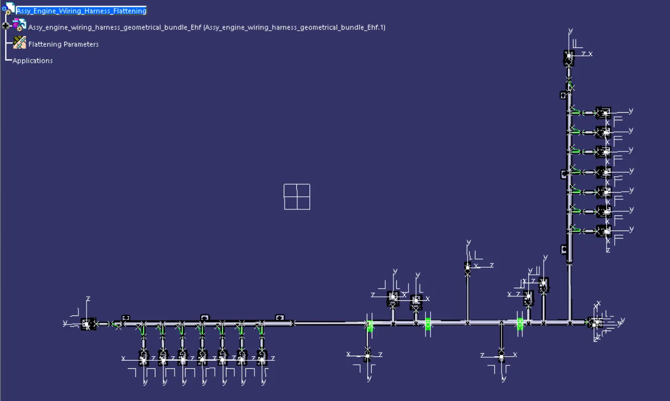
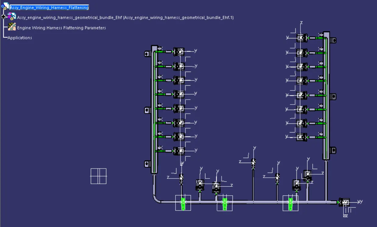
- We now align the clamps, supports, and connectors to face their mountings normal to the flattened plane to help understand the connector or clamp type in drawings. We also bend or rotate any branch as per our will to make the harness compact while drawing and presentable.
- Before we can import the geometrical bundle in the flattening assembly, we first have to configure the harness flattening parameters.
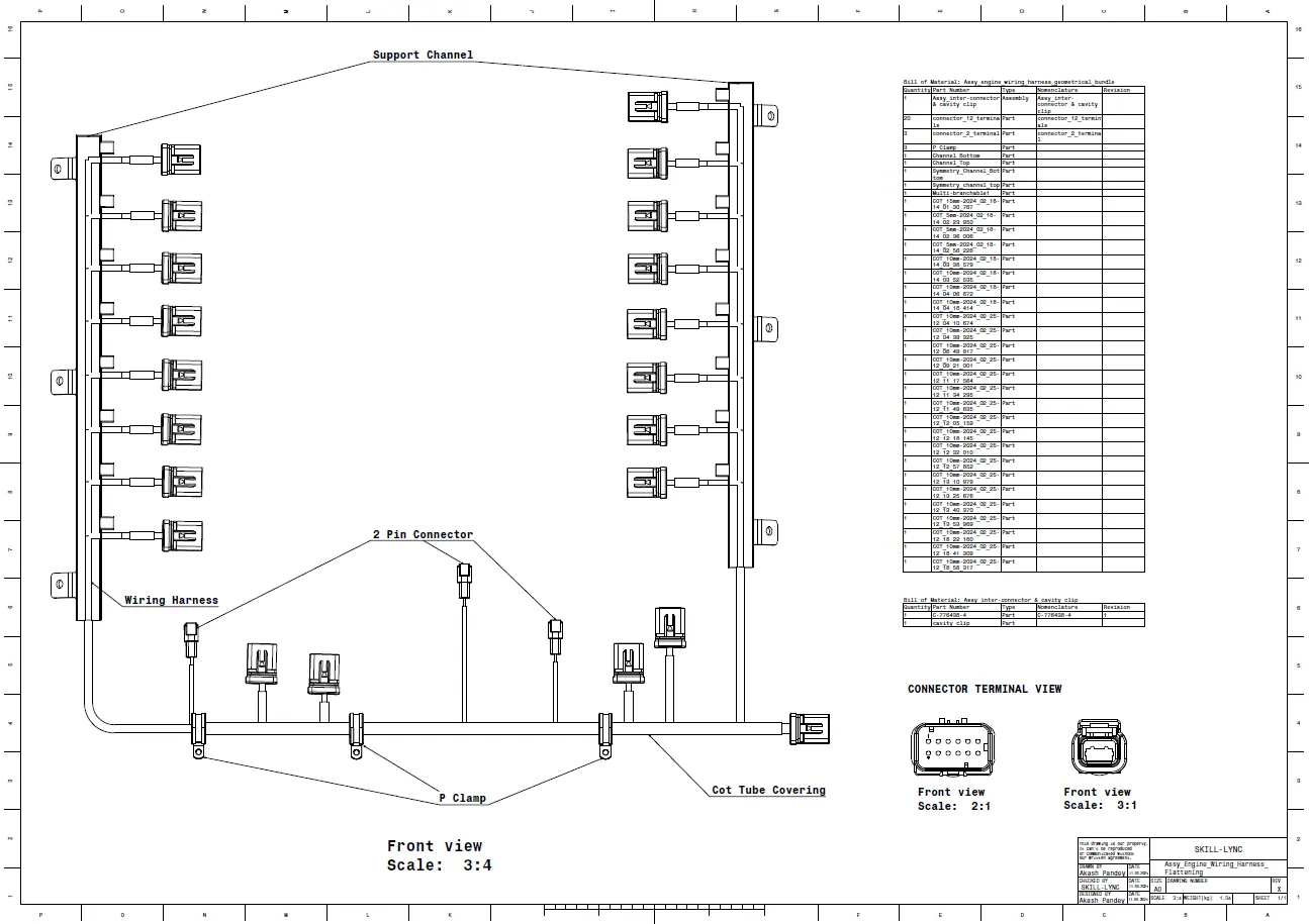
- For the final step, we create a new drawing file with the required size and import the front view of the flattened harness, and the front view of all the unique connectors used to provide terminal information. We switch to the sheet background and add a title box and Bill of Materials in the drawing.
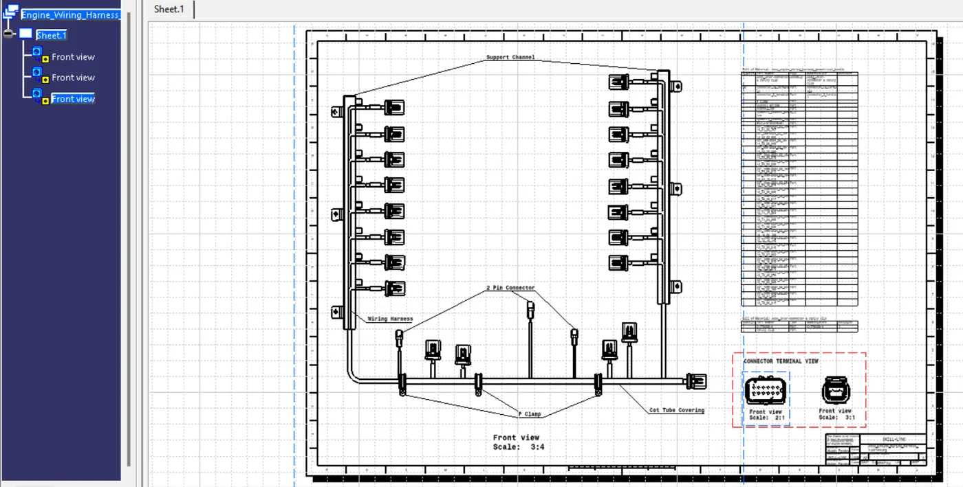
HARNESS FLATTENING DRAWING