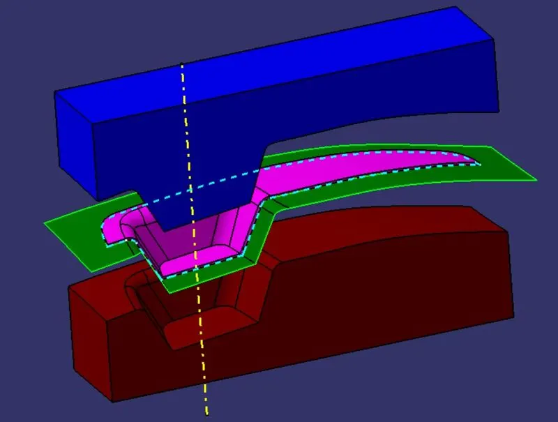
Core & Cavity Design for Switch Bezel
OBJECTIVE
To design the core and cavity for the solid Switch Bezel Plastic component.
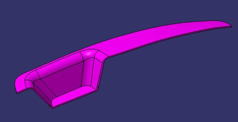
PROCEDURE
1. Defining a Tooling axis for the Class-A surface
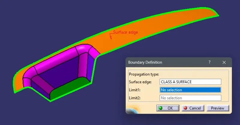
- Step 1: Check the connectivity of the surface and ensure there is no gap in the class A surface. The boundary command helps by highlighting the boundary of all the edges thus we can visually check for gaps in the class A surface.
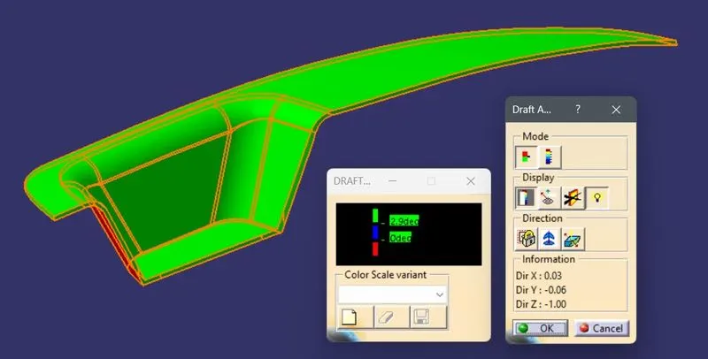
- Step 2: We perform a draft analysis on class A and check the angles of the surface we think will create problems in tooling.
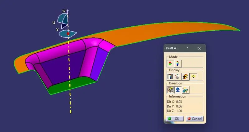
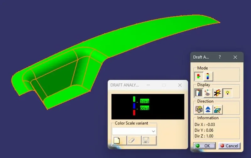
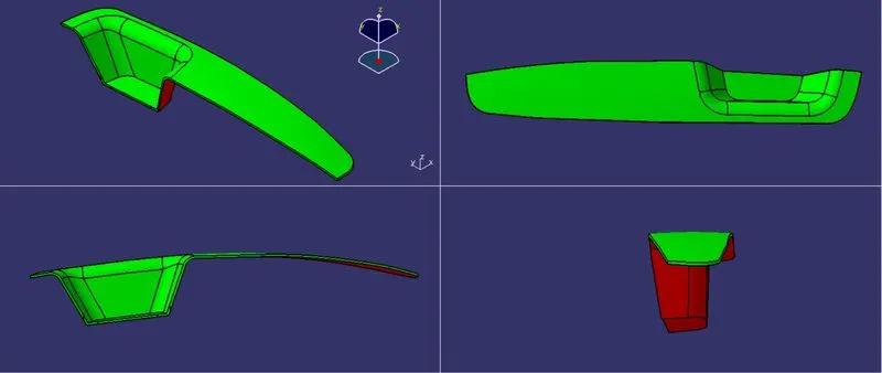
- Step 3: We observe the component from all three principal axes to get an optimum tooling axis direction. In this case, the Z axis is the optimum tooling axis.
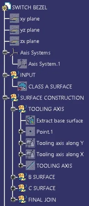
- Step 4: Next we create a dummy tooling axis along the X and Y directions. We select the base surface and create a point in the midpoint of the surface. At this point, we create an axis system and create two positioned sketches on the YZ and XZ planes.
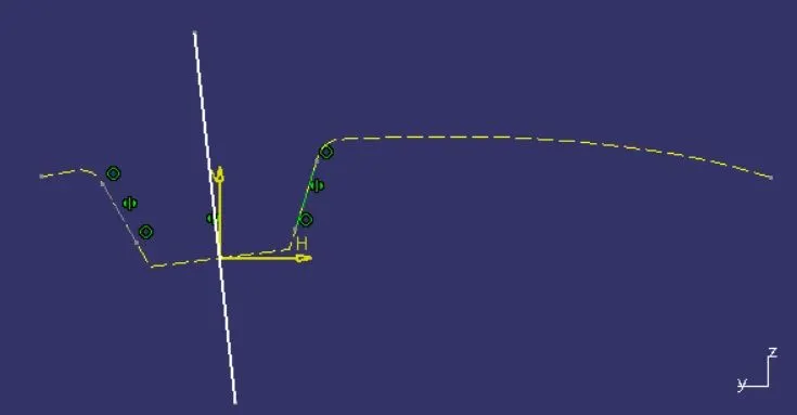
- Step 5: In the Sketcher workbench, for both YZ and XZ planes, we intersect Class A and the plane to get the surface we think will create problems in molding.
- Step 6: Using the line command we extend the parts of the curve which have small angles with the dummy tooling axis and might create a problem in molding.
- Step 7: We use the bisecting line command to bisect the angular edges through the Point on the base surface to get the dummy tooling axis along the Y direction.
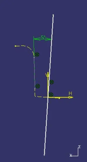
- Step 8: We similarly, create a dummy tooling axis along the X direction as well. In the X direction since we only have a single surface so we create a line at a draft angle of 5 degrees.
- Step 9: We now again create a line through the point bisecting the two dummy tooling axes to get the main tooling axis.
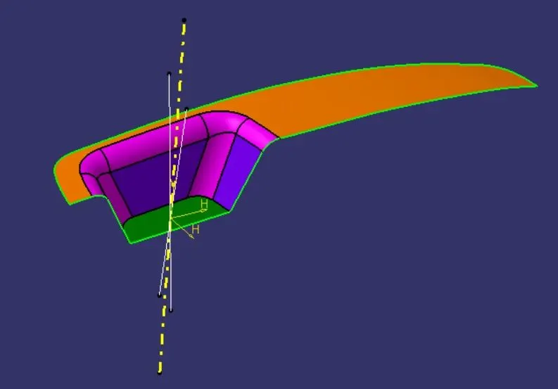
2. Creating the Parting surface
- Step 1: We create the boundary of the Class A surface and extrapolate by 15 mm.
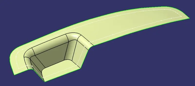
- Step 2: We now trim the extrapolated class A surface with the C surface and further with the B surface. This is the parting surface including the part area.
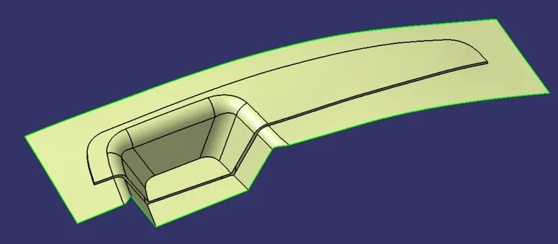
- Step 3: We now trim this surface with the C surface to get the final parting surface (in green).
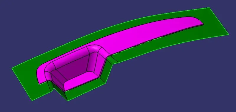
3. Creating the Core Block
- Step 1: We first create a positioned sketch in the XY plane and draw a rectangle covering the whole part surface.
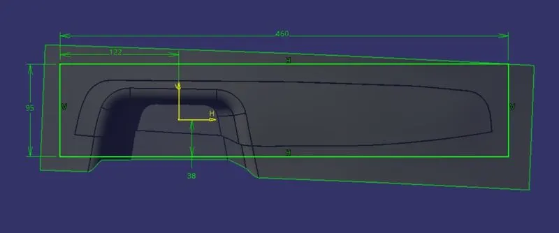
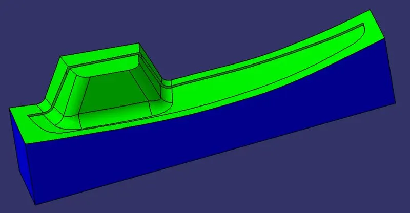
- Step 2: We then extrude this rectangle along the tooling direction and trim with the parting surface including the part area.
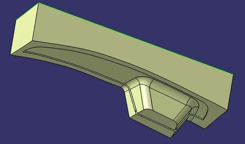
- Step 3: We use the fill and join option to close the core block surface.
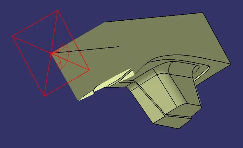
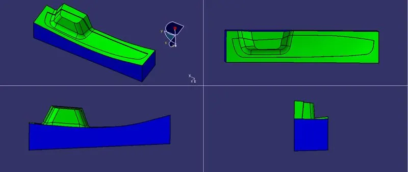
- Step 4: We now use the closesurface feature to create a final solid core block.
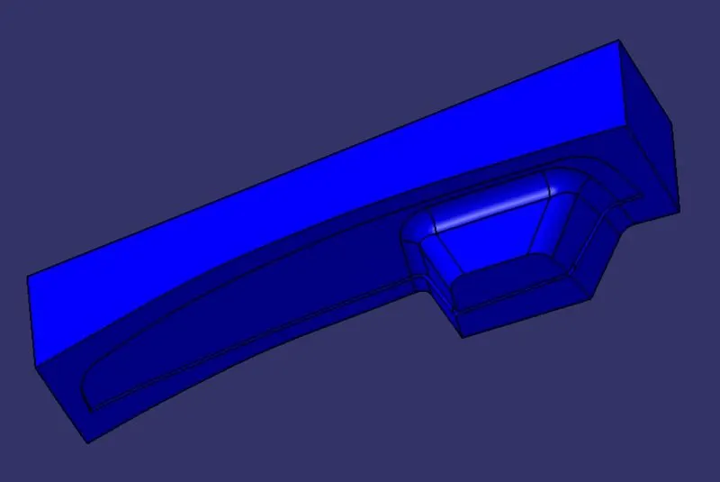
- 3D views
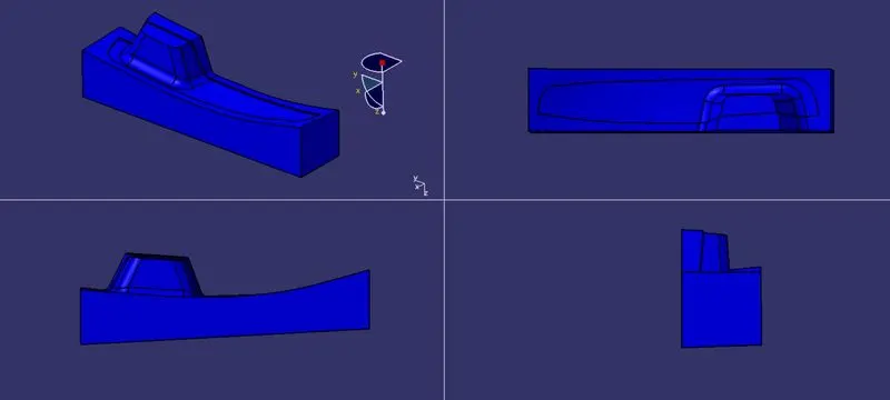
- Draft analysis
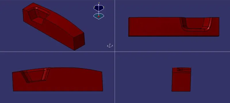
4. Creating the Cavity Block
- Step 1: We extrude the same rectangle along the tooling direction and trim with the B surface.
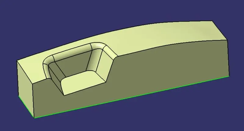
- Step 3: We use the fill and join option to close the cavity block surface.
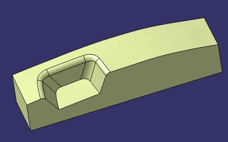
- Step 4: We now use the closesurface feature to create a final solid cavity block.
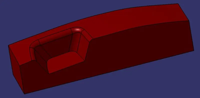
- 3D views
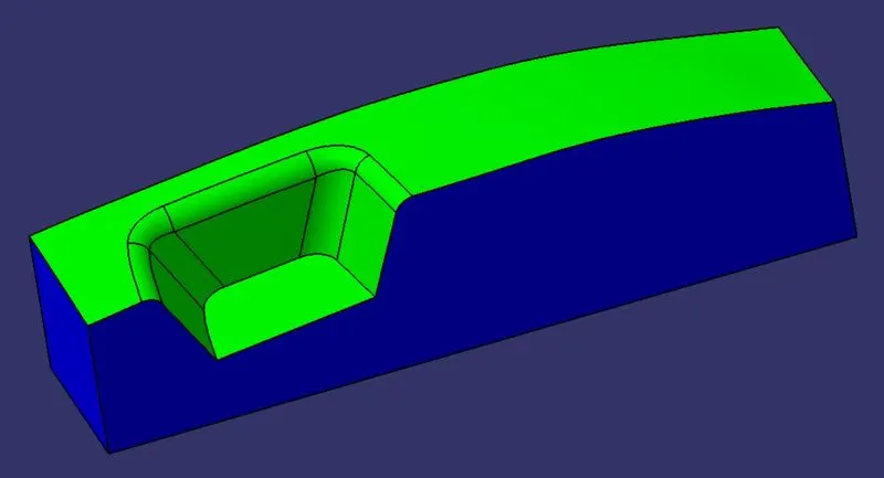
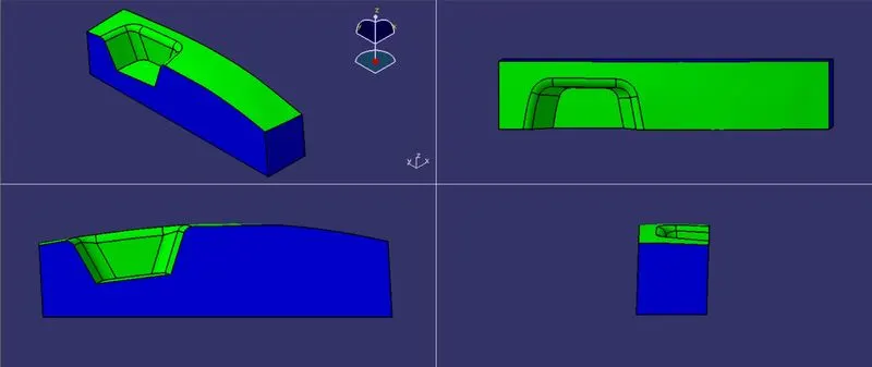
- Draft analysis
5. Creating the Parting Line
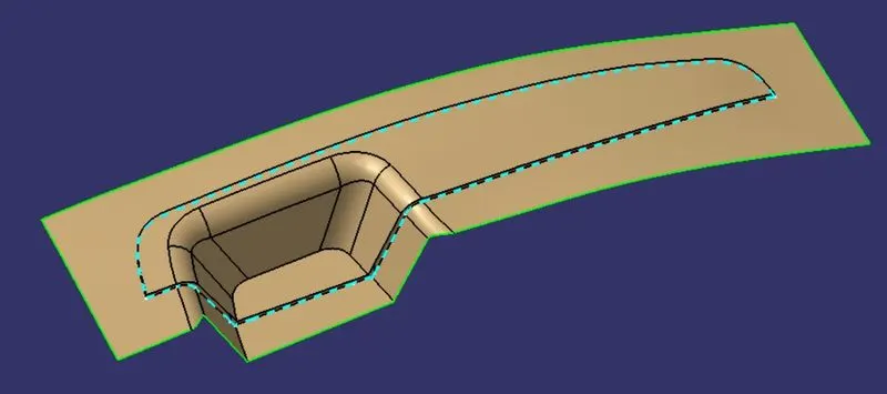
- Step 1: We use the intersection command to intersect the B surface with the C surface to get the parting line (in dotted cyan).
6. Publications
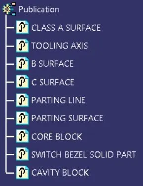
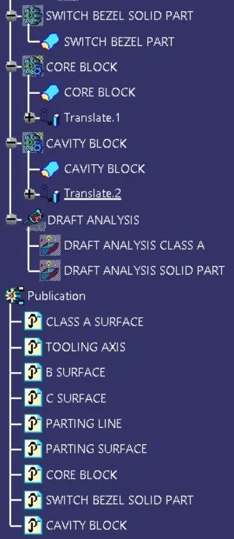
- We select the tooling axis, class A, B, and C surface, Parting Line, Parting Surface, Core Block, and Cavity Block from the tree and go to Tools->Publication to publish them.
7. Draft analysis on the final component
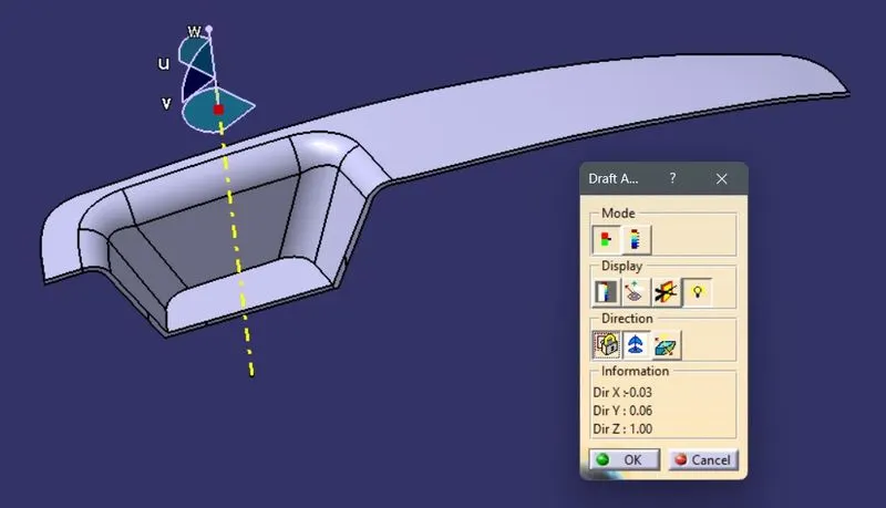
- Step 1: We open the draft analysis command box and select the compass and drag and align it with the tooling axis and lock it.
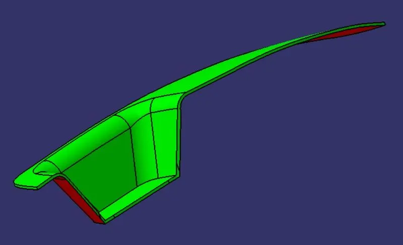
- Step 2: We analyze the color scale and input 2.9 degrees as the draft value and save the analysis.
-
All views
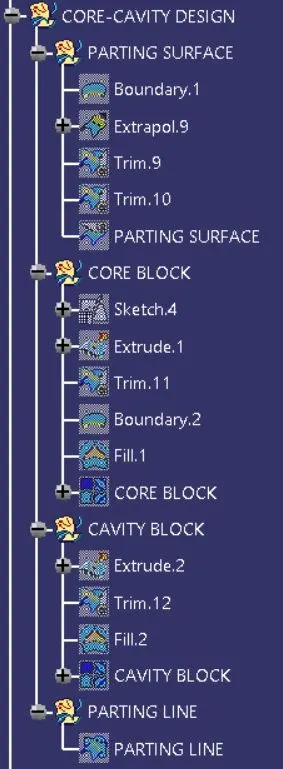
TREE STRUCTURE
RESULT