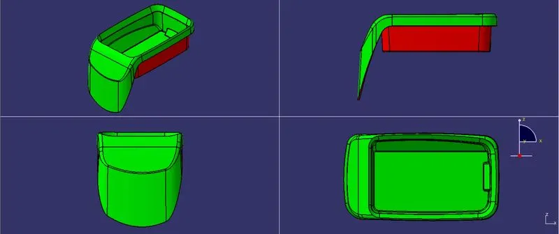
Coin Holder Design
OBJECTIVE
To design the Coin Holder Plastic component using the given Class-A surface.
PROCEDURE
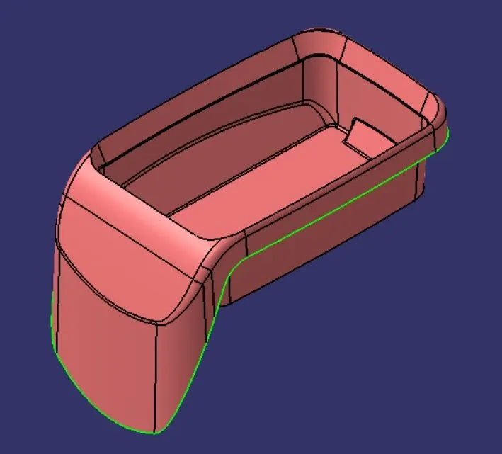
1. Defining a Tooling axis for the Class-A surface
- Step 1: Check the connectivity of the surface and ensure there is no gap in the class A surface. The boundary command helps by highlighting the boundary of all the edges thus we can visually check for gaps in the class A surface.
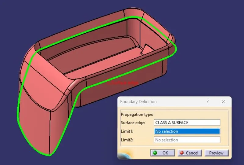
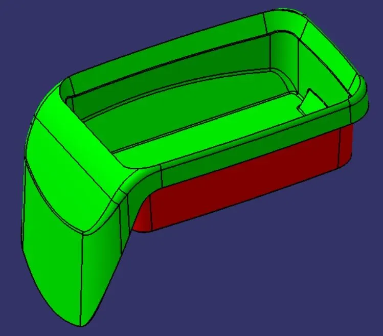
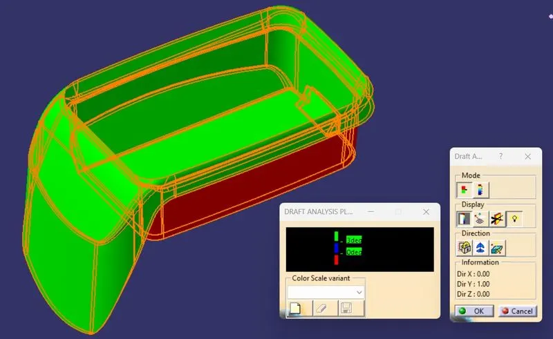
- Step 2: We perform a draft analysis on class A and check the angles of the surface we think will create problems in tooling.
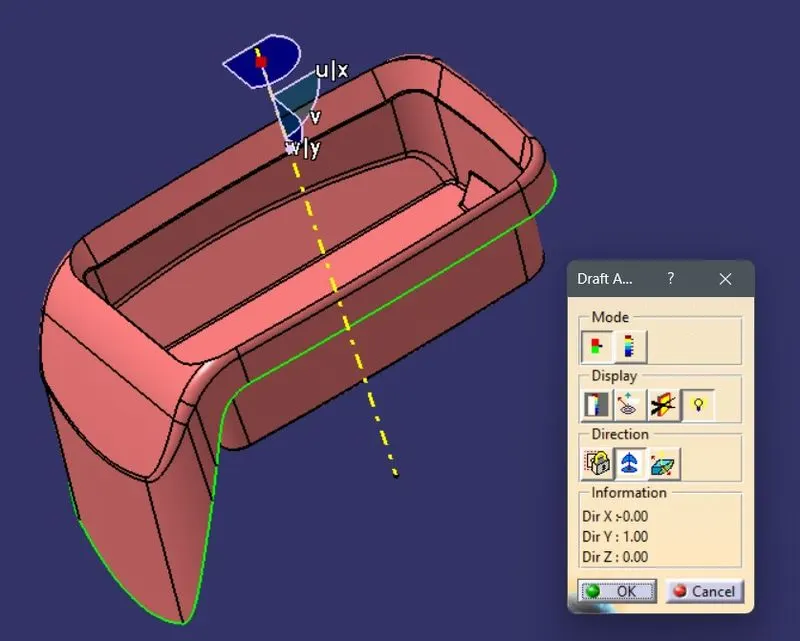
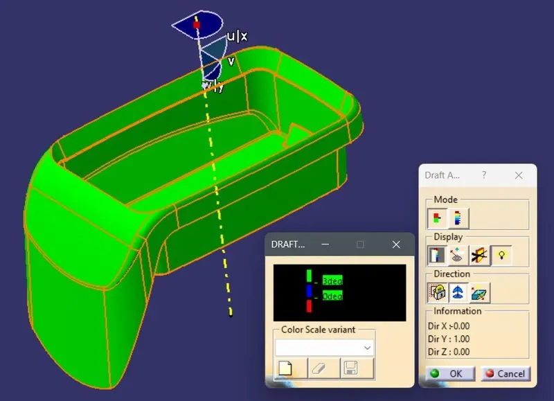
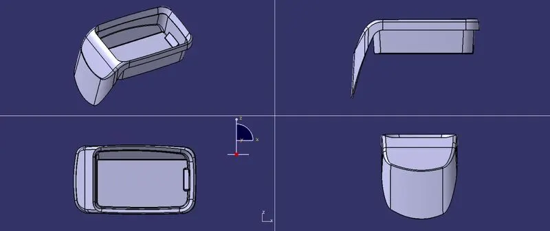
- Step 3: We observe the component from all three principal axes to get an optimum tooling axis direction. In this case, since there is a bin so the bin surface will be selected as the tooling direction i.e., the Y axis is the optimum tooling axis.
- Step 4: Next we create an axis system at the center of the base surface and create an intersection with the Class A surface. since we see that the bin walls are parallel to the Y direction so the Y axis can be considered as the tooling axis.
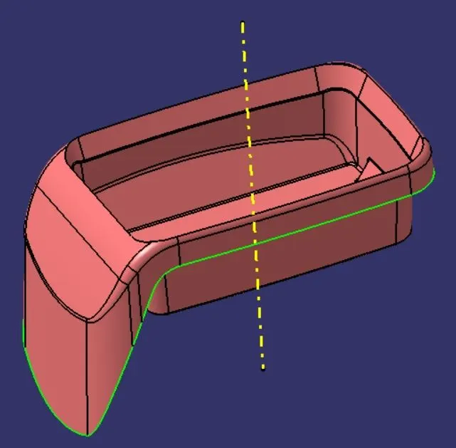
2. Creating Class B surface
- Step 1: The class A surface has fillets and they will create errors in offset so we first divide Class A into simple surfaces namely the Side Wall, Base, Top Wall, and Outer Flange.
- Step 2:We create COIN HOLDER SURFACE geometrical surface and start with the Side Wall surface and use the Extract and Untrim command to get the parent surface which we offset as per the thickness of the component i.e, 2.5mm outwards to the class A surface. Then we Extrapolate all 4 surfaces so they intersect each other and trim them together to get the side wall surface.
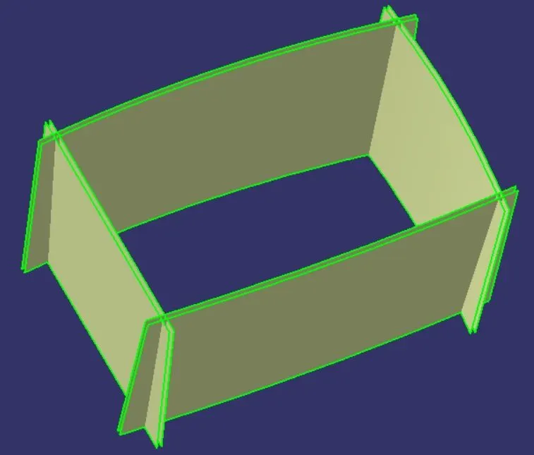
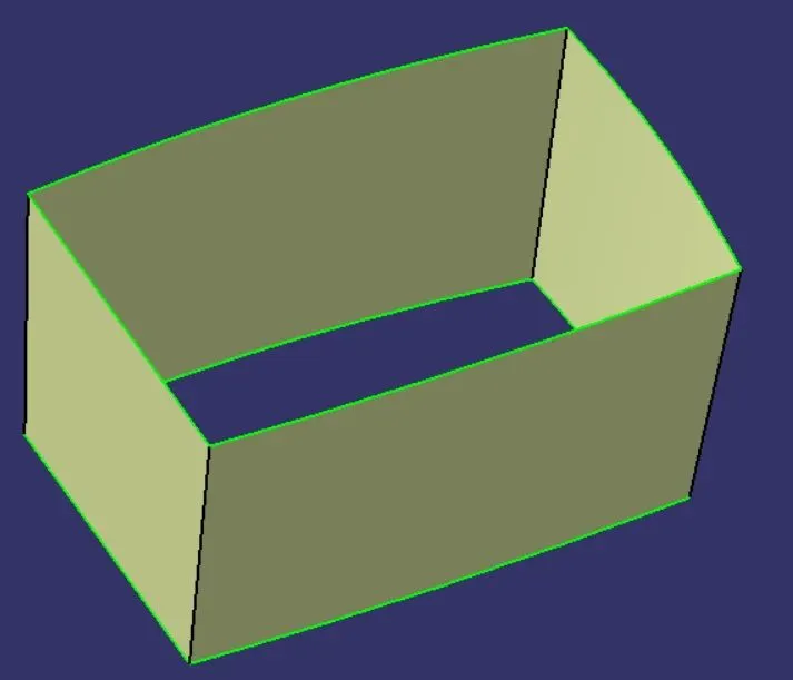
- Step 3: We then create Base Surface geometrical surface and start with the two base wall surfaces and use the Extract, Untrim, and extrapolate commands to get the parent surfaces respectively which we offset at 2.5mm to get the required surface.
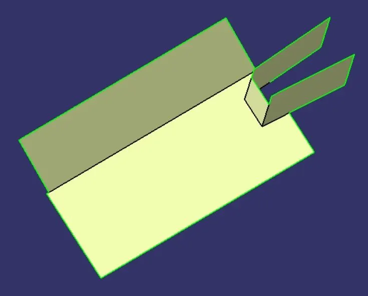
- Step 4: We then create a Top Wall Surface geometrical set and Extract, Untrim, and Extrapolate the base surface to get the parent surfaces which we offset at 2.5mm to get the required surface.
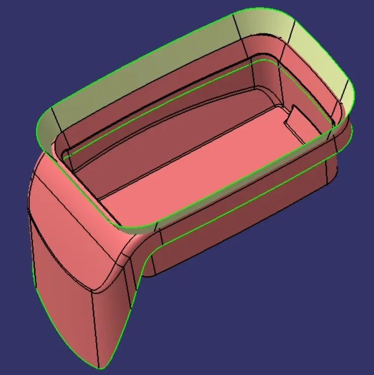
- Step 5: We then create Outer Flange Surface geometrical set and Extract, Untrim, and Extrapolate the Flange surface to get the 2 parent surfaces which we offset at 2.5mm to get the required surfaces.
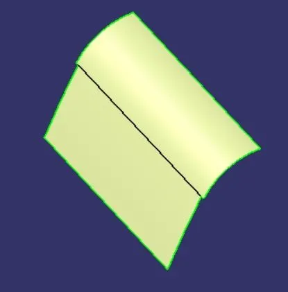
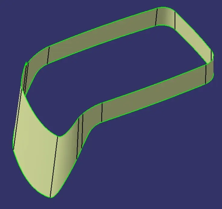
- Step 6: We then use the Trim command in a new geometrical set to join the above surfaces into one.
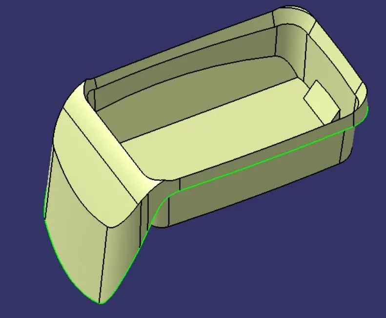
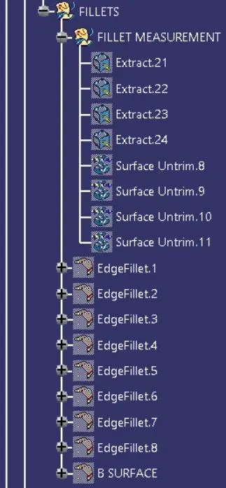
- Step 6: We create a new geometrical set for fillets and measure fillets. We extract filleted surfaces from class A and untrim them and measure the edges to get the exact fillet radius values. The fillets are then created to get the final B surface.
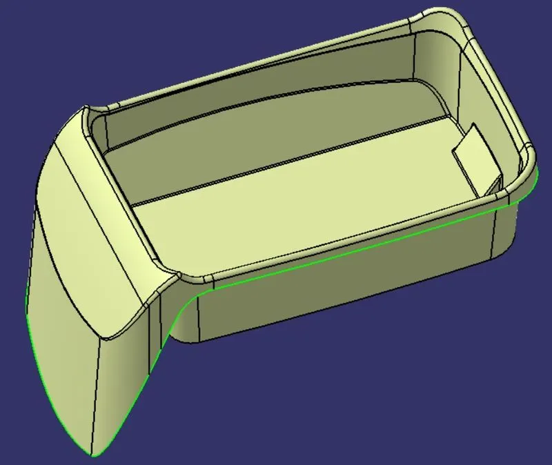
3. Creating Class C surface
- Step 1: We use the Multiple Extract command to extract the boundary of the class A surface and smoothen them using the smooth curve operation.
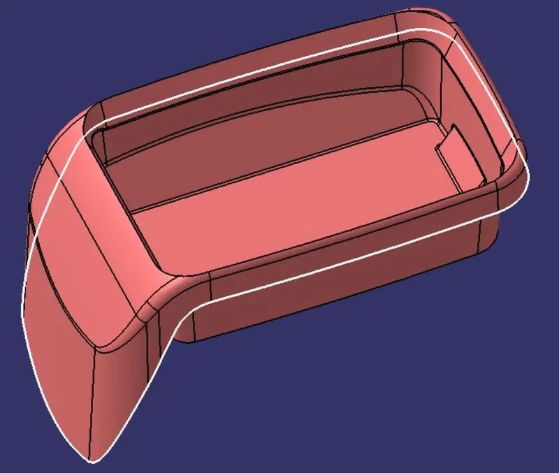
- Step 2: We also use the Multiple Extract command to extract the surfaces of the class A which are adjacent to the boundary.
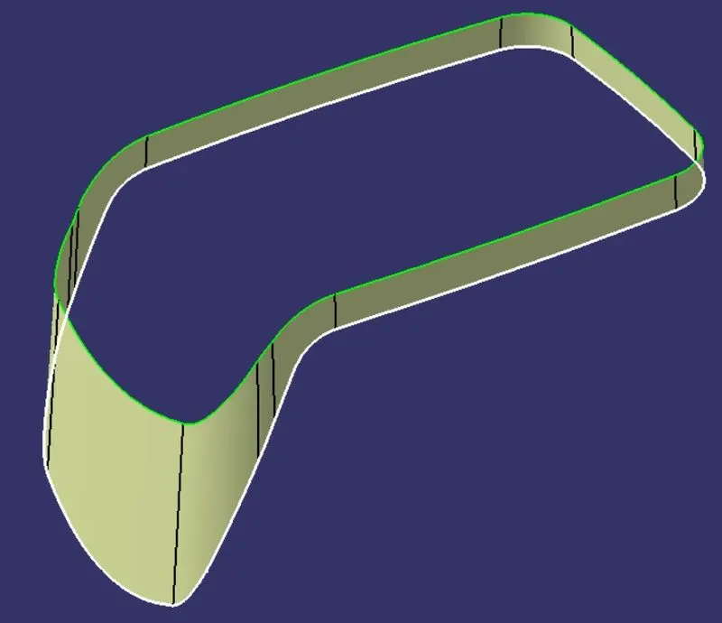
- Step 3: We perform the sweep operation along the boundary as a guide curve with the extracted surface as the reference surface for a length of 4mm towards the inside and an angle of 90 degrees.
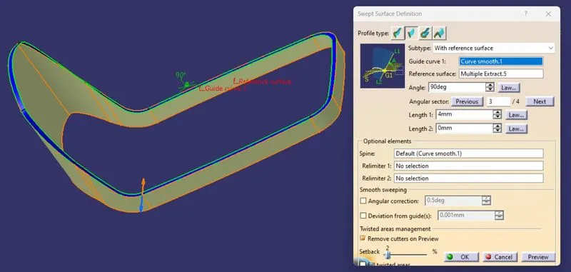
- Step 4: The surface thus formed is the final C surface.
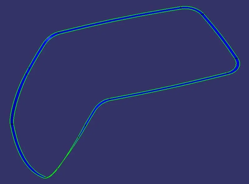
4. Creating the hollow surface part
- Step 1: We use the trim operation to cut and join the Class A, B, and C surfaces into one body to get the final surface body.
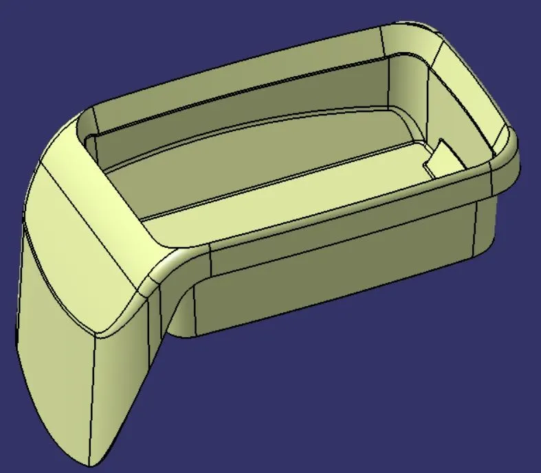
5. Publication of the Tooling axis, Class A, B, and C surfaces
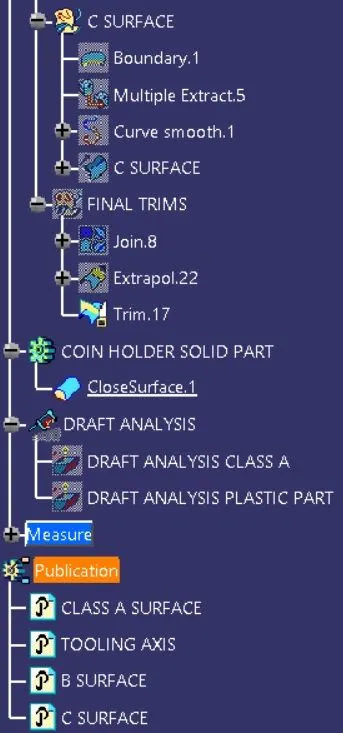
- Step 1: We select the tooling axis, class A, B, and C surface from the tree and go to Tools->Publication to publish them.
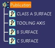
6. Creating the final solid component
- Step 1: We switch to the part design workbench and use the Closesurface feature to create the solid part out of the hollow surface body.
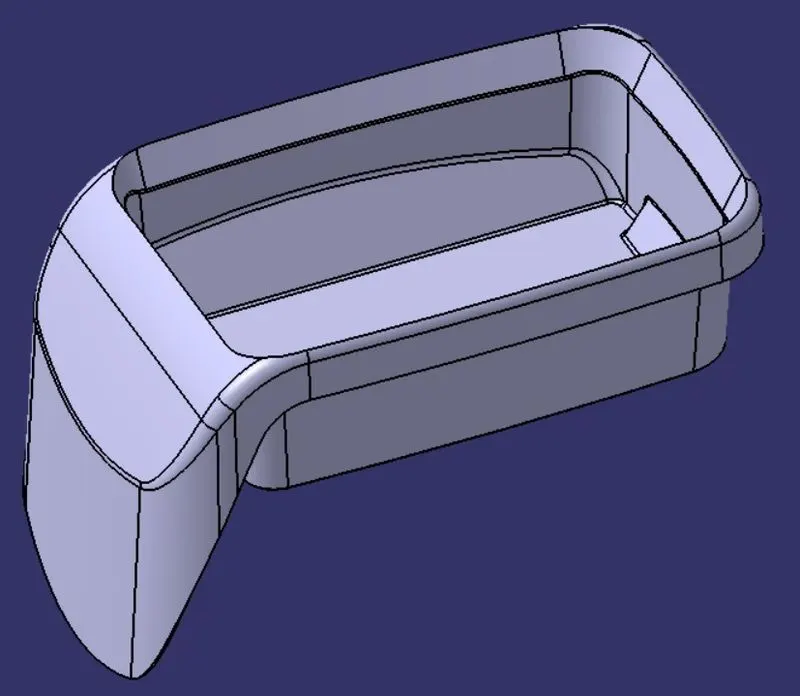
all views
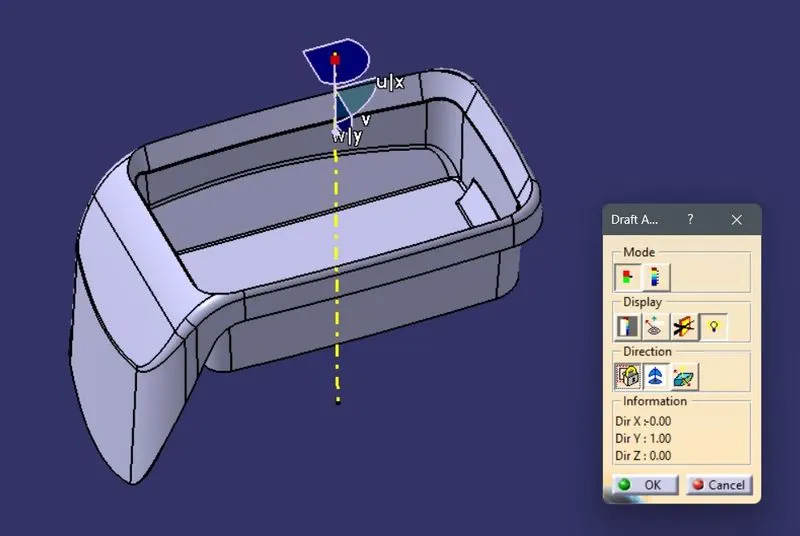
7. Draft analysis on the final component.
- Step 1: We open the draft analysis command box and select the compass and drag and align it with the tooling axis and lock it.
- Step 2: We analyze the color scale and input 3 degrees as the draft value and save the analysis.
TREE STRUCTURE
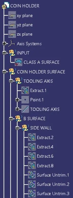
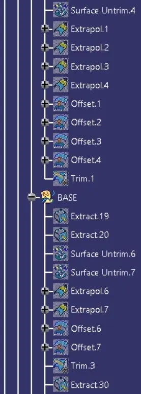
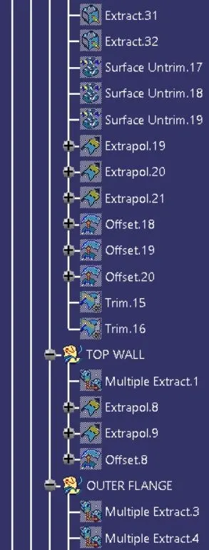
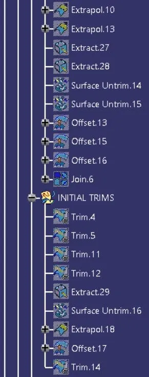
DRAFT ANALYSIS
1. For Class-A surface
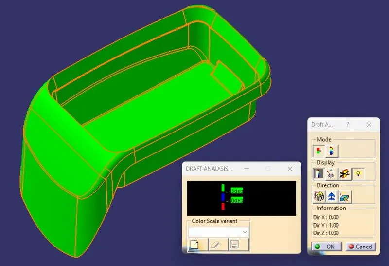
All views
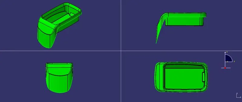
2. For the final plastic component
All views