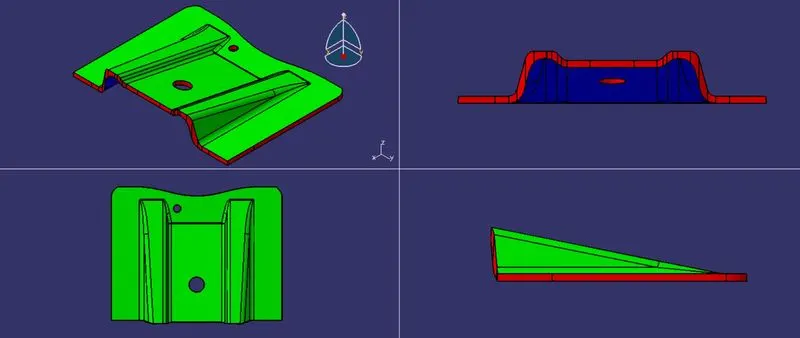
Base Bracket Design
OBJECTIVE
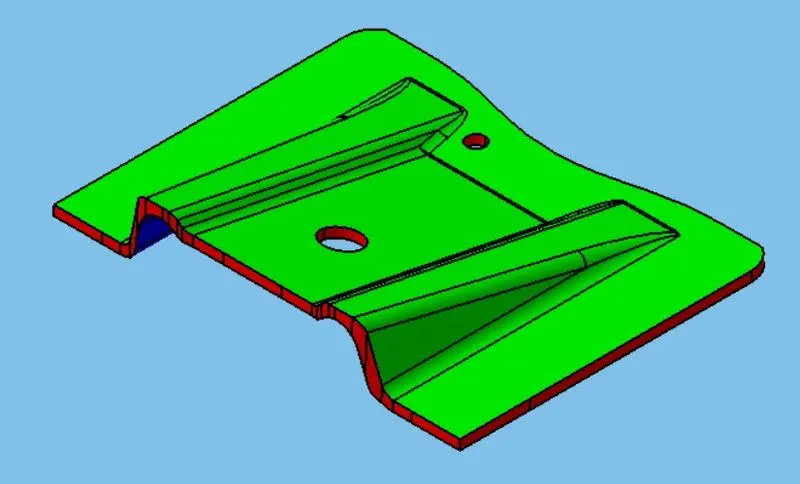
To design the Base Bracket Plastic component using the given Class-A surface.
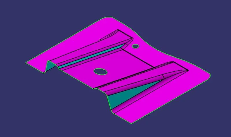
PROCEDURE
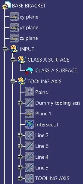
1. Defining a Tooling axis for the Class-A surface
- Step 1: Check the connectivity of the surface and ensure there is no gap between the surfaces. The boundary command helps by highlighting the boundary of all the edges thus we can visually check for gaps in the class A surface.
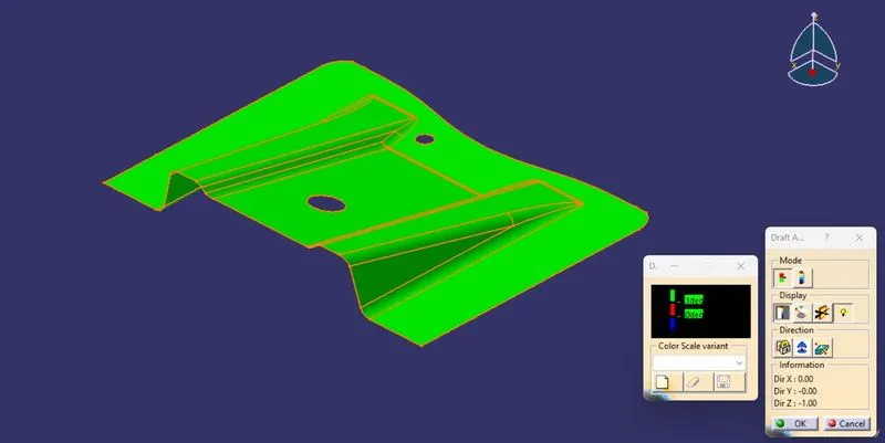
- Step 2: We perform a draft analysis on class A and check the angles of the surface we think will create problems in tooling.
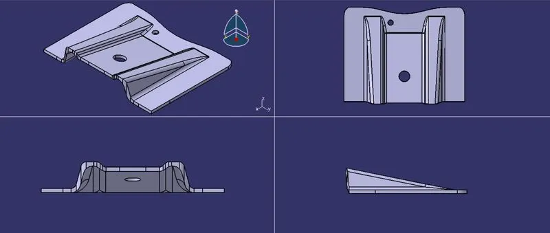
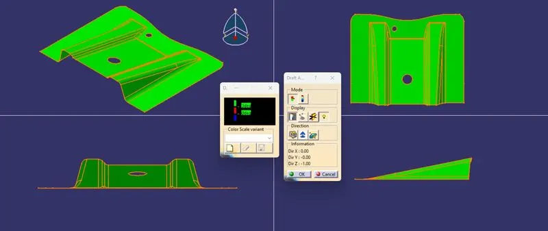
- Step 3: We observe the component from all three principal axes to get an optimum tooling axis direction. In this case, the part can't be tooled along the X or Y axis as the holes will be difficult to form in the main tooling. The Z axis is thus the optimum tooling axis.
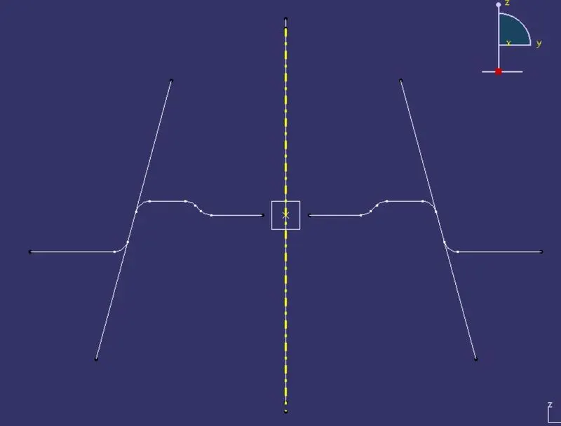
- Step 4: Next we create a dummy tooling axis. If the component has a large flat surface or holes then it will be best to select the surface or hole to create the tooling axis. Here the hole in the middle slope is selected for the tooling axis. We create a dummy axis using a line command through the center of the hole along the Z direction.
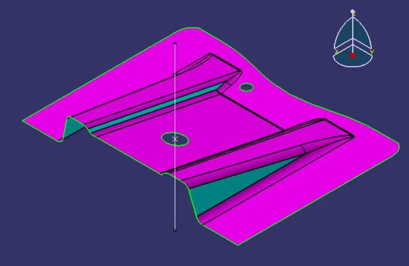
- Step 5: We create a plane parallel to the YZ plane through the center of the hole we selected. Using the intersection command we project a curve on the Class A surface where this plane cuts.
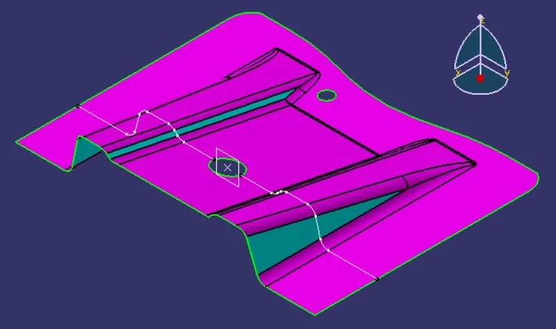
- Step 6: Using the line command we extend the parts of the curve which have small angles with the dummy tooling axis and might create a problem in molding.
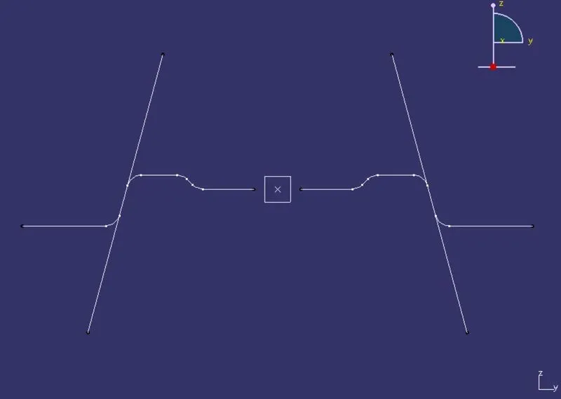
- Step 7: We use the bisecting line command to bisect the angular edges through the center of the hole. This is our Main Tooling axis.
2. Creating Class B surface
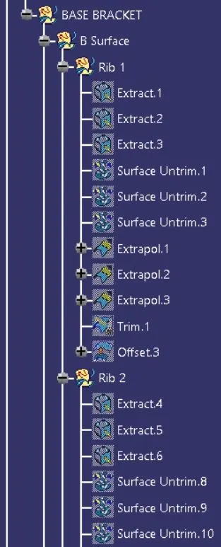
- Step 1: The class A surface has fillets and they will create errors in offset so we use the extract command to extract the straight faces of the first rib in the Rib 1 geometrical set.

- Step 2: We untrim the three surfaces of Rib 1 and use extrapolate command to expand the surfaces by 10mm on every side.

- Step 3: Then we trim all three surfaces into the required shape to create a single surface.
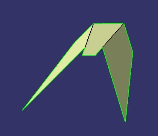
- Step 4: We then use offset to create a copy of the trimmed rib surface at a distance equal to the thickness of the part below the class A surface.
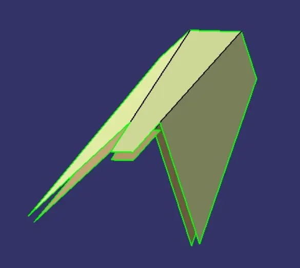
- Step 5: We similarly create the offset of the second Rib in its own Rib 2 geometrical set.
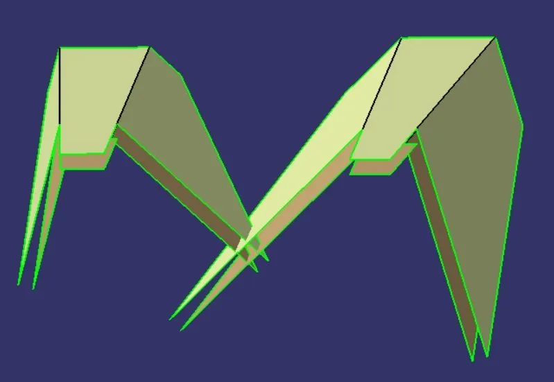
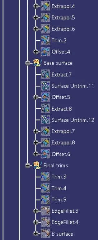
- Step 6: We now extract the middle slope surface using the extract command and untrim it. Using the extrapolate command we expand the surface such that it intersects well with the ribs and offset it for 2.5mm below the parent surface.
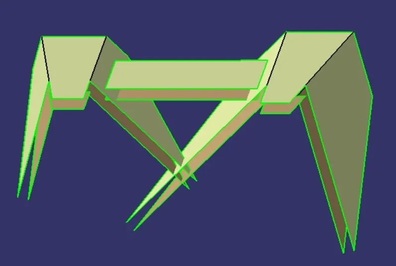
- Step 7: Similarly we extract and untrim the base surface and extrapolate it. We offset it for 2.5 mm below the class A surface.
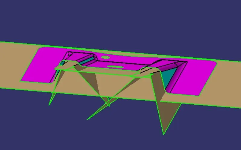
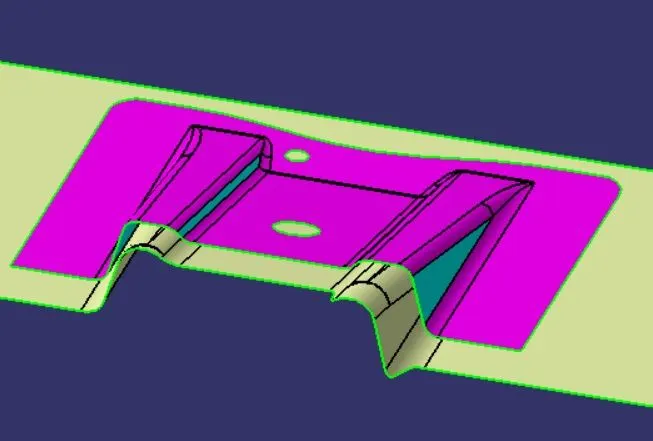
- Step 8: We now trim all the surfaces together and give the edge fillets of radius 3 mm to get the Class B surface.
3. Creating Class C surface
- Step 1: We use boundary command to extract the outer edge of the class A surface and perform a sweep operation with draft direction along the tooling axis with a draft angle of 3 degrees and for 10 mm of length towards the B surface.
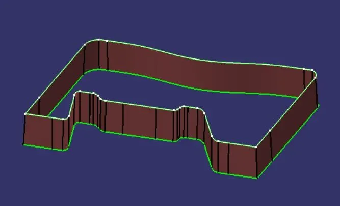
- Step 2: Similarly, we sweep the holes with draft angles towards the B surface.
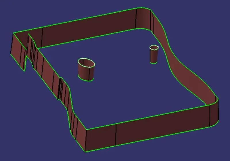
- Step 3: Then we use the join operation to join all the surfaces into one. This is the C surface.
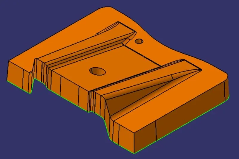
4. Creating the hollow surface part
- Step 1: We use the trim operation to cut and join the Class B, and C surfaces into one body to get the final surface body.
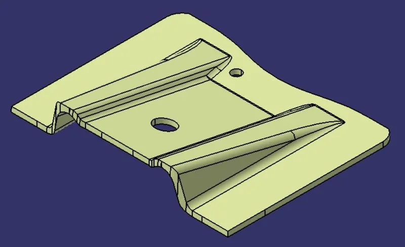
5. Publication of the Tooling axis, Class A, B, and C surfaces
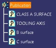
- Step 1: We select the tooling axis, class A, B, and C surface from the tree and go to Tools->Publication to publish them.
6. Creating the final solid component
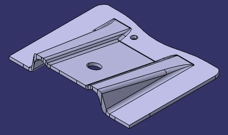
- Step 1: We switch to the part design workbench and use the closesurface feature to create the solid part out of the hollow surface body.
all views
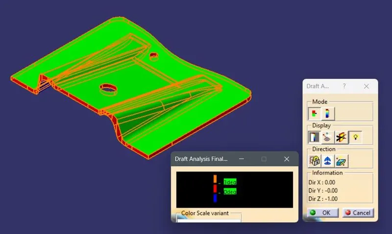
7. Draft analysis on the final component.
- Step 1: We open the draft analysis command box and select the compass and drag and align it with the tooling axis and lock it.
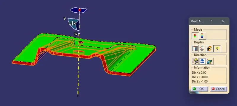
- Step 2: We analyze the color scale and input 3 degrees as the draft value and save the analysis.
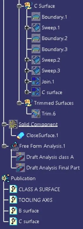
TREE STRUCTURE
DRAFT ANALYSIS
1. For Class-A surface
All views
2. For the final plastic component
All views