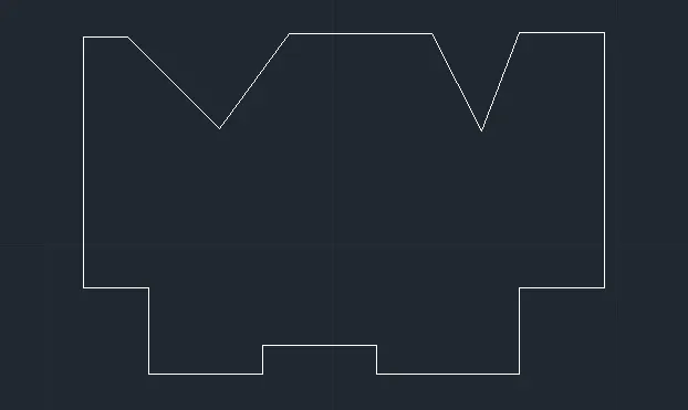
Drafting of various geometries using Chamfer, Fillet tool in AutoCad
Q1;
Aim:
To create the geometries using all the coordinates system methods.
To create the Line tool to create the geometries and use circle tool when required
Procedure:
Enter the unit command and change into decimal.
Select the line tool from the ribbon tab and specify the first point
Specify the first point has 3.00 meter
Specify the next point has 2.12 meters
Specify the next point has 2.83 meters
Specify the next point has 2.00 meters
Specify the next point has 2.00 meters
Specify the next point has 3.50 meter or choose the close command and close the line tool.
Select the circle tool and specify the 1st circle with radius 1.20.
Specify the 2nd circle with the radius 0.80.
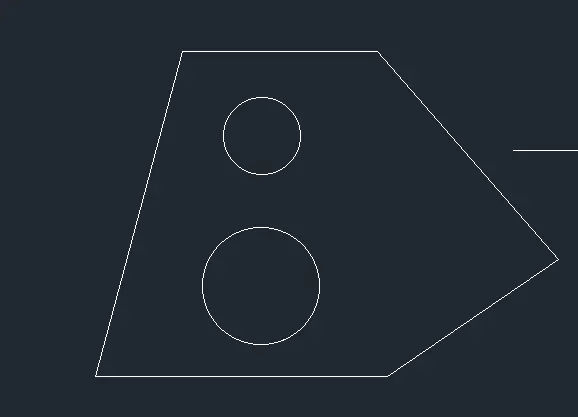
Q2;
Aim:
To create the geometries using all the coordinates system methods.
To create the Line tool to create the geometries and use circle tool when required
Procedure:
Enter the unit command and change the length into Architectural.
Select the line tool from the ribbon tab and specify the first point
Specify the first point has 8
Specify the next point has 2’-5”
Specify the next point has 3’
Specify the next point has 2’-6”
Specify the next point has 2’
Specify the next point has 2’-10”
Specify the next point has 1’9” and close the line or entre close command and close the line tool.
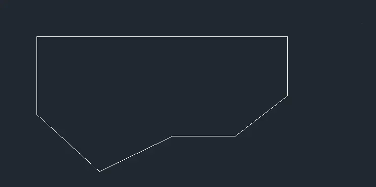
Q3;
Aim:
To create the geometries using all the coordinates system methods.
To create the Line tool to create the geometries and use circle tool when required
Procedure:
Enter the unit command and change the units in Engineering.
Select the line tool from the ribbon tab or enter L in the command box and specify the first point.
Specify the first point has 5’-0.1”
Specify the next point has 1’-60”
Specify the next point has 3’
Specify the next point has 2’-66.5”
Specify the next point has 3’-3.0” or entre the close command and close the line.
Select the circle tool from the ribbon tab or entre the C in the command box.
Specify the circle in the middle of the box with radius of 2’-6.5”.
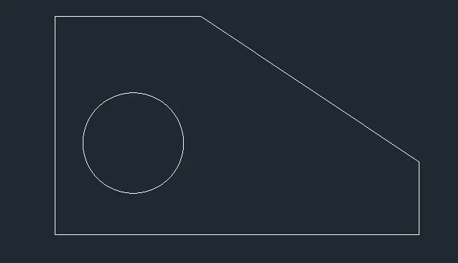
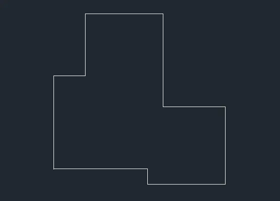
Q4;
Aim:
To create the geometries using all the coordinates system methods.
To create the Line tool to create the geometries and use circle tool when required
Procedure:
Select the line tool from the ribbon tab or enter the L in the command and specify the first point
Specify the first point has 3.00
Specify the next point has 0.50
Specify the next point has 2.50
Specify the next point has 2.50
Specify the next point has 2.00
Specify the next point has 2.50
Specify the next point has 2.00
Specify the next point has 1.00
Specify the next point has 3.50 and close the line command.
Q5;
Aim:
To create the geometries using all the coordinates system methods.
To create the Line tool to create the geometries and use circle tool when required
Procedure:
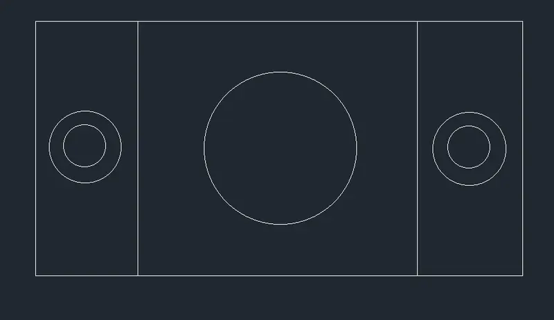
Select the line tool from the ribbon tab or enter L in the command box and specify the first point.
Specify the first point has 11.50
Specify the next point has 6.00
Specify the next point has 11.50
Specify the next point has 6.00
Close the line command
Step 2:
Select the line tool and draw a line from the top of the line with the length of 6.00
Close the line tool
Step 3:
Select the line tool from the ribbon tab and specify the next line on the right side and draw a line of 6.00 length.
Close the line command.
Step 4:
Select the circle tool from the ribbon tab or enter C in the command box.
Specify a circle in the 2 boxes which drawn before in the box with the radius of
Specify the first circle with radius 2.00
Q6;
Aim:
To create the geometries using all the coordinates system methods.
To create the Line tool to create the geometries and use circle tool when required
Procedure:
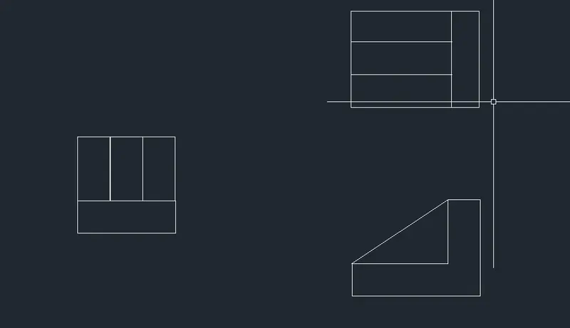
Select the line tool from the ribbon tab or enter L in the command box and specify the first point.
Specify the first point has 2.00
Specify the next point has 1.50
Specify the next point has 0.50
Specify the next point has 1.00
Specify the next point has 1.50
Specify the next point has 0.50
Close the line command.
Enter the line command and draw a horizontal line from 2edge points.
Close the line command.
Step 2:
Select the rectangle command from the ribbon tab or enter the REC in the command box and specify the first point
Draw the rectangle with length 2.00 and breath with 2.00.
Close the rectangle tool.
Step 3:
Select the line tool from the ribbon tab and draw 2 line horizontally with 1.50 length.
Draw a straight line with length 2.00 and breath 0.50.
Step 4:
Select the rectangle tool from the ribbon tab and specify the first point.
Draw a rectangle box with length 1.50 and breath 1.50
Close the rectangle tool
Step 5:
Select the line tool from the ribbon tab and specify 2 lines with length 1.00 and breath 0.50.
Draw another line inside the box vertically with length 1.50.
Close the line tool.
Q7;
Aim:
To create the geometries using all the coordinates system methods.
To create the Line tool to create the geometries and use circle tool when required
Procedure:
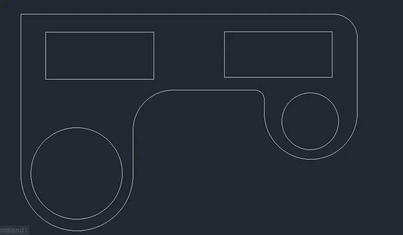
Enter the units in the command box and change into engineering.
Select the line tool from the ribbon tab and specify the first point
Specify the first point 210 inches
Specify the next point has 75 inches
End the line tool and enter fillet option and apply on it with R15
Close the fillet command.
Step 2:
Select the arc from the ribbon tab and draw a arc with R25 .
Close the arc command
Step 3:
Select the line tool
Specify the next point has 15inches
Specify the next point has 30inches
End the line tool and enter the fillet option and apply fillet with R6
Exit the fillet command
Step 4:
Enter the arc command and draw a arc with R35
Close the arc tool
Step 5:
Select the line tool and enter close option.
Close the line tool select the circle tool and draw the 1st ciecle in the arc with R50.
Draw the 2nd circle with radius of 30 and close the circle tool
Step 6:
Select the rectangle tool and draw two rectangle in the box with 15 inches length and 25 inches breath.
Close the rectangle command.
Q8;
Aim:
To create the geometries using all the coordinates system methods.
To create the Line tool to create the geometries and use circle tool when required
Procedure:
Select the circle tool from the ribbon tab.
Specify the first circle with R4.00
Specify the next circle with R5.00
Exit the line tool.
Step 2:
Select the line tool and draw parallel lines to the circle at both the sides.
Close the line tool
Select the fillet command and apply fillet on the both sides with R6
Close the fillet command.
Step 3:
Select the circle tool and draw 2 small circles with 0.90
And close the circle tool.

Q9;
Aim:
To create the geometries using all the coordinates system methods.
To create the Line tool to create the geometries and use circle tool when required
Procedure:
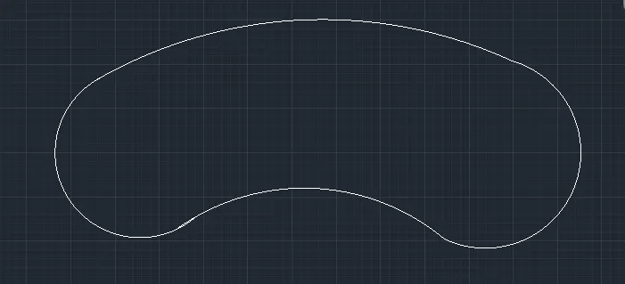
Select the circle tool from the ribbon tab
Specify 2 circles
1st circle with radius R8
2ND circle with radius R9
Close the circle tool
Step 2:
Select the arc tool from the ribbon tab and draw 2 arcs parallel to 2circles with
Specify the first arc has R41
Specify the 2nd arc has R20
Close the arc command
Step 3:
Select the trim command and trim the overlapping and the extra lines to form the exact image.
Close the trim command.
Q10;
Aim:
To create the geometries using all the coordinates system methods.
To create the Line tool to create the geometries and use circle tool when required
Procedure:
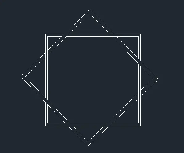
Select the rectangle tool from the ribbon tab
Specify 1st rectangle with length 7.00 and breath 7.00
Specify 2nd rectangle with length 6.80 and breath 6.80
Close the rectangle command.
Step 2:
Select the polygon command from the ribbon tab
Specify the 2 polygons with 4 sides has per the rectangle.
Exit the polygon command.
Step 3:
Select the trim option and trim the overlapping lines and trim the extra lines shown in the drawing.
Exit the trim tool.
Q11;
Aim:
To create the geometries using all the coordinates system methods.
To create the Line tool to create the geometries and use circle tool when required
Procedure:
Select the line tool from the ribbon tab or enter L in the command box
Specify the first line has 3’
Specify the 2nd line has 4’
Specify the 3rd line has 4’
Specify the 4th line has 4’-2”
Specify the 5th line has 4’-6”
Specify the 6th line has 4’
Specify the 7th line has 3’
Specify the 8th line has 9’
Specify the 9th line has 3’
Specify the next line has 3’-7”
Specify the next line has 6’
Specify the next line has 3’-7”
Specify the next line has 3’
Select the close option and close the line
Exit line tool
Step 2:
Select the polygon and specify in the box with 4edges and 3 inches length.
Exit the polygon tool.