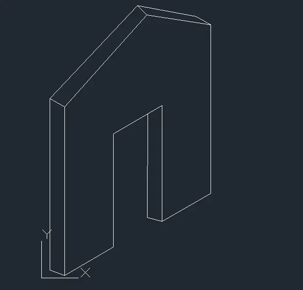
Creating a Floor plan, Footing detail and Isometric view using AutoCad
Q1:
Aim:
To create the geometries using all the coordinates system methods.
To create the Line tool to create the geometries and use circle tool when required.
Procedure:
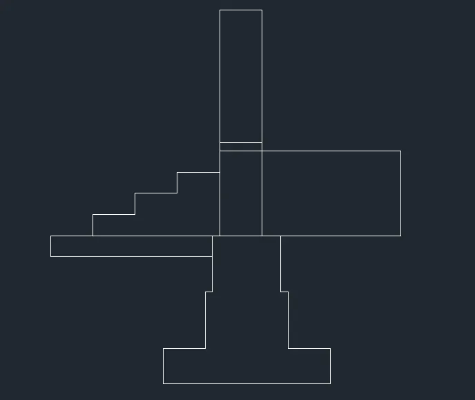
Step 1;
Select the tool from the ribbon tab and specify the first-dimension line from the starting point. And ortho should be on.
Specify the first line has 1:15 meter
Step 2;
Exit the line tool and again enter the line command and specify 4 steps from the starting point of 1:15 line
Specify the length has 0.15 meter
Specify the breath has 0.30 meter
Specify the next line has 1.00 meter to the upward direction
Specify the next line horizontally with 0.30 meter
Specify the next point downwards with 1.00 meter and close the line command.
Step 3;
Select the line tool from the ribbon tab and start the line from the middle of the line drawn before.
Specify the line horizontally of 1.00 meter
Specify the next line vertically of 0.60 meter
Specify the next line horizontally of 1.00 meter
And close the line and press esc and exit line tool.
Step 4;
Select the line tool from the ribbon tab and specify the next rectangle from the previous end point.
Specify the first rectangle with 0.40 length and breath.
Specify the second box attached with the first rectangle with 0.50 breath and 0.40 breath.
Specify the next rectangle with 0.90 breath and 0.25 length
And close the rectangle command.
Enter trim command and trim the lines between the rectangle.
Q2:
Aim:
To create the geometries using all the coordinates system methods.
To create the Line tool to create the geometries and use circle tool when required.
Procedure:
Step 1;
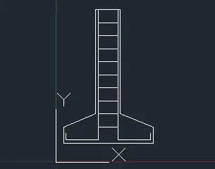
Select line tool from the ribbon tab and specify the first line. And ortho should be on.
First create the outer line,
Specify the first line 1.60 meter
Specify the next line 0.38 meter
Specify the next line 0.25 meter
Specify the next line 1.00 meter
Specify the next line has 0.25 meter
Specify the next line has 0.38 meter
Specify the next line has 1.60 meter
Specify the next line has 0.25 meter ana close the line tool.
Step 2;
Now select the inside line with distance of 0.04 from the outer line.
Select the line command from the ribbon tool,
Specify a box with 0.20 length and 0.30 breath.
Exit the rectangle tool and enter copy command,
Copy the rectangle and select array option and form 9 arrays and enter fit option.
Step 3;
Select the line tool from the ribbon tab and specify two line from the both end of the rectangles. Exit the line command.
Q3:
Aim:
To create the geometries using all the coordinates system methods.
To create the Line tool to create the geometries and use circle tool when required.
Procedure:
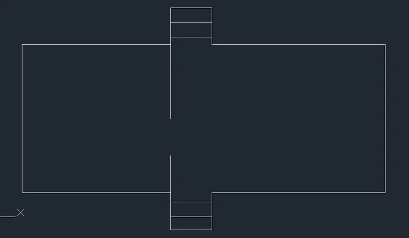
Select line tool from the ribbon tab and specify the first dimension line. And ortho should be on.
Specify the first line has 3.60 meter
Specify the next line has 3.60 meter
Specify the next point has 0.90 meter
Specify the next point has 1.00 meter
Specify the next point has 0.90 meter.
Step 2;
Enter line command and specify 2lines with distance of 0.30 meter .
Step 3;
Enter the line command and specify the line from the previous point.
Specify the line has 4.20 meter.
Specify the next line has 3.60 meter.
Specify the next line has 4.20 meter.
Specify the next line has 0.90 meter.
Specify the next line has 1.00 meter.
Specify the next line has 0.90 meter.
Step 4;
Enter line command and specify 2lines with distance of 0.30 meter .
Step 5;
Select line tool from the ribbon tab and specify the next line,
Specify the next line has 3.60 meter
Enter close command and close the line.
Q4:
Aim:
To create the geometries using all the coordinates system methods.
To create the Line tool to create the geometries and use circle tool when required.
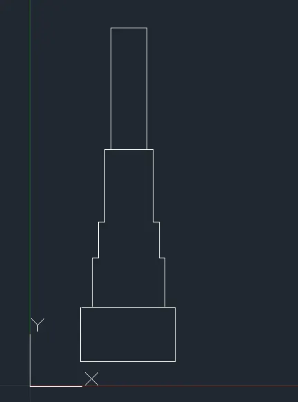
Procedure:
Step 1;
Select the rectangle tool form from the ribbon tab and specify the first rectangle. Ortho should be on.
Specify the first rectangle length 1.00 and breath 0.30 meters.
Specify the next rectangle length 0.60 and breath 0.40 meters.
Specify the next rectangle length 0.30 and breath 0.50 meters.
Specify the next rectangle length 0.0.45 and breath 0.90 meters.
close the rectangle command.
Step 2;
Enter the trim command and trim the lines between the rectangle.
Q5:
Aim:
To create the geometries using all the coordinates system methods.
To create the Line tool to create the geometries and use circle tool when required.
Procedure:
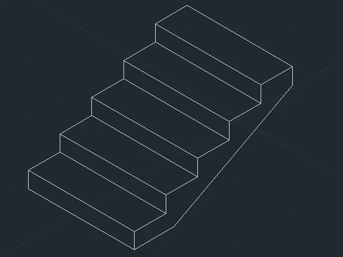
step 1;
Select the line tool from the ribbon tab and on the isometric and ortho also should be on.
Specify the first line has 1.00 meter
Specify the next line has 0.15 meter
Specify the next line has 1.00 meter
Specify the next line has 0.15 meter
Specify the next line has 0.30 meter
Specify the next line has 1.00 meter
Specify the next line has 0.38 meter
Close the line command with pressing esc
Step 2;
Enter the copy command and copy the first step and select the bottom command and copy.
Select the bottom point and copy the step.
Close the copy command.
Q6:
Aim:
To create the geometries using all the coordinates system methods.
To create the Line tool to create the geometries and use circle tool when required.
Procedure:
On the isometric and the ortho and select the line tool from the ribbon and specify the first line.
Step 1;
Specify the first line has 3.00 meters
Specify the next line has 0.30 meter
Specify the next line has 1.00 meter
Specify the next line has 2.42 meter
Specify the next line has 1.00 meter
Specify the next line has 2.42 meter
Step 2;
Enter the line command and specify line ha 0.30 and 2.00 meter and close the line.
Step 3;
Enter the line tool and specify the next line ,
Specify the next line has 1.00 meter
Specify the next line has 3.25 meter
Specify the next line has 0.90 meter
Specify the next line has 1.00 meter
Close the line command
Step 4;
Enter the line command and create the outer line of the drawing
Specify the next line has 3.00 meter
Specify the next line has 1.00 meter
Specify the next line has o.90 meter
Exit the line command by pressing esc.
Enter the close command and close the line.